Voltage Sag Mitigation in Utility Distribution
System Using STATCOM with Hysteresis
Current Controller
Laxmi Lata
1, Dr.M.K.Elango
2PG Student [Power Systems Engineering], Dept. of EEE, K.S.Rangasamy College of Technology, Tiruchengode,
Tamilnadu, India 1
Professor, Dept. of EEE, K.S.Rangasamy College of Technology, Tiruchengode, Tamilnadu, India2
ABSTRACT: This paper presents three phase Voltage Source Inverter based STATCOM using Hysteresis current controller for mitigating voltage sag due to sudden increase in load. A STATCOM injects a current to the system such that it negates the effect of nonlinear current waveform generated by load. Three phases Voltage Source Inverter based on MOSFET is designed and firing pulses to the device is given by hysteresis current controller, which produces proper switching frequency to the inverter to manipulate the voltage sag during change in load. Advantage of the proposed method is that it eliminates the need of modulator. This model compensates the voltage sag with efficient and effective manner. Because of its fast dynamic response to any disturbance, the STATCOM offer improved quality of supply by giving an inherently faster response and greater output to a system with depressed voltage. The STATCOM using Hysteresis current controller scheme in distribution system for power quality improvement is simulated using MATLAB/SIMULINK in power system block set. The results produced by this method are validated with the Statcom using space vector modulation technique.
KEYWORDS: Power Quality, Static Synchronous Compensator (STATCOM), Voltage sag, Switching Frequency, Hysteresis Current Controller.
I.INTRODUCTION
Nowadays, Electric utility and customers both require high level of quality of electric power Poor power quality is characterized as voltage sag, voltage swell, harmonic distortion, voltage interruption, transient and surges. Among these, voltage sag is the common. The effects of a sag are often more noticeable than those of a swell. Sag of duration longer than three cycles is often visible in a reduction in the output of lights. Reactive power exchange improves the network stability by increasing the voltage collapse limit [1].Grid codes from the transmission system is introduced for supporting the voltage under grid fault [2].combination of active rectifiers and constant power loads can exchange small amount of reactive power based on their ratings [3].To overcome this problem method of generating the reference signal for UPQC is introduced .It consists of shunt converter mainly for eliminating current harmonics and series converter for compensating voltage sag/voltage swell [4]. To mitigate the voltage sag problem, various methods based on the application of series (DVR) and parallel (DSTATCOM) custom power devices are discussed in [5]. In order to support the grid voltage during voltage sag distributed generation system is very important [6]. For power quality improvement DSTATCOM fed by Photo Voltaic (PV) array are introduced for power quality improvement in distribution system. The Icos Ф algorithm is introduced here for DSTATCOM [7]. For the application of custom power devices, wide range of controller become came to know among these, the Static Synchronous Compensator based on VSC principle is mostly used.
The objective of this paper is to propose a controller for Statcom during voltage sag that is able to support the grid voltage under voltage sag. Hysteresis current controller doesn’t need modulator as it generates the switching frequency by comparing directly the actual current with reference current. By controlling the magnitude and phase angle of the output voltage of the VSC, both active and reactive power can be exchanged between the distribution system and the STATCOM. The device should be installed as close to the sensitive load to maximize the compensating capability. Voltage Source Converter is the main component of the STATCOM .The STATCOM has a function of compensating reactive power, absorbing the harmonics and compensating the voltage sag. This paper is focus on the function of compensating voltage sag.
II.SYSTEM DESCRIPTION AND CONTROL SYSTEM OF STATCOM
This section describes the general description of STATCOM, and the proposed control system of STATCOM. This system consists of STATCOM connected to the grid in order to compensate voltage sag and control method to produce switching frequency to the inverter.
A. Static Synchronous Compensator (STATCOM)
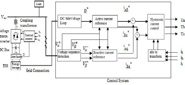
In fig 1, it shows the Generating system connected to the load through the Grid. If the load is suddenly increases means current increases and thereby voltage reduces. So we cannot able to give the quality of power to the end user .In order to compensate this problem STATCOM is connected to the grid, thereby it needed the pulses for VSC to inject compensating current. Proper switching frequency is generated by the controller. In this work Hysteresis Current Control is used. Capacitor is connected across the VSC to maintain constant dc voltage in order to allow the operation of Voltage Source Converter (VSC).
Fig. 1 Diagram of power system with STATCOM
B.
Control System of STATCOMIn fig 2, it shows the block diagram of STATCOM with control system. The voltage at the PCC and the current at the converter side are sensed and given as an input to the control system. This control system produces control input u and having following objectives [1].
1) For compensating power loss it should be ensure that small active power absorption is necessary from the AC network. This is done by regulating the capacitor voltage Vdc to the voltage set point Vdc*.
2) Safe operation of STATCOM means the current should not be exceeded. To ensure this, A current set point I* is employed.
Fig. 2 Control System of STATCOM
The internal loop of a control system is designed to provide fast and accurate current control. The external loop is responsible for generating the current references. The inputs of the controller are the measured phase voltages v at the Point Of Common Coupling (PCC), the current i and the dc link voltage Vdc.
Voltage v and current i are transformed into Stationary Reference Frame (SRF) values. Voltage Vα and Vβ are then
decomposed into symmetric components using a sequence extractor.
vα= vα++ v
α− 1
vβ= vβ++ v β− (2)
This symmetric voltage can be defined as vα+= v+cos wt +φ+ (3)
vβ+= v+sin wt +φ+ (4)
vα−= v−cos −wt −φ− (5)
vβ−= v−sin −wt −φ− (6)
The symmetric sequence extractor is a key aspect to characterize the grid voltage. The dc-link voltage regulator is in charge of the active power reference P∗ that keeps power balance. The voltage support block needs first to detect the voltage sag. This can be done by computing the voltage rms in each phase. When one or several rms values drop below a predefined threshold, the voltage support control is activated. The voltage Vα and Vβ are given to the reactive current reference to generate reactive current of both the sequence. iα∗q= 2 3 kqvβ++(1−kq)vβ− kq(v+)2+(1−kq)(v−)2Q ∗ (7
)
Similarly active power reference is given to the active current reference there it compares the power with voltage to generate active current of both the sequence.
iα∗p= 2 3
vα+ (v+)2P
∗ (9)
iβp∗ = 2 3
vβ+ (v+)2P
∗ (10)
The active current reference and reactive current reference are the compared to generate the actual current reference for hysteresis current controller. The current references is generated according to the set point V*dc and I*.
iα∗= iα∗p+ iα∗q (11)
iβ∗= i
βp ∗ + i
βq
∗ (12)
In hysteresis current controller, actual current reference and the current derived from ABC to αβ transform are compared to generate the switching signal for inverter, thereby control can be done.
III.REVIEW OF CONVENTIONAL CONTROL STRATEGY
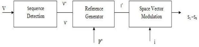
In fig 3, it shows the basic block diagram during voltage sag. To compensate voltage sags, the inverter should be injecting the compensating current into the grid. so, first we should know the sequence of voltage coming to the grid .Voltage sequence detector perform this function. These sequences of voltage then given to reference generation block to generate the reference current vector with the use of voltage sequences and the reference power signal that is generated from the DC link voltage controller[15]. Finally the space vector modulation, one of the methods for controlling pulse width modulation is used to derive the control signals for the device.
Fig. 3 Control Block Diagram
IV.PROPOSED CONTOL METHOD
In fig 4, it shows the structure of hysteresis current controller where SI, SII, SIII, SIV, SV, SVI. These switching signals are
generating by comparison of actual current as ia, ib, ic. in the respective phase with the reference signal as ia, ref, ib,ref and
ic, ref in the respective phase.
Fig. 4 Structure of Hysteresis Current Controller
In this work hysteresis current controller is implemented in control block of inverter. As explained in above example for the control of heater temperature limit is setting likewise here for mitigating voltage sag, first it should check the voltage thereby lower limit of voltage with tolerance value is setting here. When the voltage is below this value, the STATCOM comes into action and by comparing the voltage difference between the inverter and the PCC, injected current is derived. In the control block, inputs to the inverter are DC capacitor voltage Vdc , reference current is also set,
converter side current Ig-abc, and initial lower limit of voltage that is essential for starting the process . Vdc is regulated to
Vdc* and by comparing its present and previous value id* current is derived. This is considered as an inverter current. I g-abc is converted to dq reference frame thereby deriving Ide and Iqe current then comparing id* with Ide and iq* with Iqe ,
error signals are generating finally by comparing this error signal with actual current thereby switching frequency to the inverter are derived.
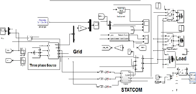
Fig.5 Simulation Model in MATLAB/SIMULINK
sec to 0.8 sec is created in this scheme. In this scheme three phase RL load is connected to the grid, another three phase RL load of same rating is connected to the grid with the help of circuit breaker. In this work STATCOM Voltage Source Inverter (VSI) is connected between the three phase source and the load. The voltage sag mitigation by using STATCOM in this scheme is used to attain the voltage stability. Here, Hysteresis current control method is used to generate pulses for VSI.
V. SIMULATION RESULTS AND DISCUSSION
Table.1 Comparison between the proposed method and existing method
In table 1, it shows the comparison between the proposed method and the existing method. The system has simulated using the proposed STATCOM with Hysteresis current controller.
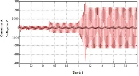
In fig 6, it shows the source voltage is affected when other three phase load are suddenly connected.
Fig. 6 Source Voltage and Current
In fig7, it shows the load current, STATCOM current and rms value of load current waveform. Till 0.5 sec only first load is there, after 0.5 sec second load is connected so there is increase in load current. Up to 0.5 sec current value is 20 amps. When the second load is connected current value rises from 20 amps to 40 amps. During voltage reduction, STATCOM need to inject current into injected into the grid, hence the current value of STATCOM is negative. Load current increases when the second 3 phase RL load is connected. the grid. Current is injected into the grid hence the current value of STATCOM is negative. Load current increases when the second 3 phase RL load is connected.
Parameters STATCOM using hysteresis
current controller
STATCOM using space vector modulation
Voltage sag 0.9 pu 0.85 pu
Statcom current 17 Amps 10 Amps
Reactive power injected 0.80pu 0.74pu
Fig. 7 (a) Load Current, 7(b) STATCOM Current and 7(c) Load Current RMS Value
In fig 8, it shows RMS value of voltage in the grid, voltage sag, reference voltage and load current. voltage sag in the grid due to connection of the another 3 phase RL load .Till 0.5 sec grid voltage is same as that of source voltage .After the second 3 phase RL load is connected there is reduction in voltage i.e. Voltage sag, duration of voltage sag is 0.5 sec to 0.8 sec. At this moment STATCOM starts injecting current into the grid by the use of Hysteresis current controller to mitigate the voltage sag, and then we get a smooth sinusoidal voltage waveform. Up to 0.5 sec load current is 20 amps, when the other 3 phase RL load of same rating is connected then the load current increases.
Fig. 8(a) RMS Voltage in Grid, 8(b)Voltage in Grid, 8(c) Reference Voltage , 8(d) Load Current
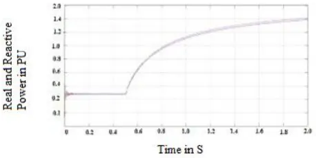
In fig 9, it shows the active and reactive power of the system. During first load, there is no big change in Real power and reactive power. First the real power is increased from 0.2 to 0.4 pu and after 0.15 sec it lowers to 0.3 pu till 0.5 sec. After 0.5sec when the second load is connected then both real and reactive power is increased from 0.35 pu to 0.9 pu but the difference is very small between them because at that time STATCOM comes into action due to voltage sag.
VI.CONCLUSION
A complete control scheme for STATCOM under Voltage sag has been presented in this paper. The objective of this work is to study the performance of STATCOM for mitigating voltage sag and to improve the quality of power to the end user. STATCOM using Hysteresis Current Controller has been investigated for voltage sag. It is clear from the simulation results that the STATCOM using Hysteresis current controller is simple and is generating the pulses for VSC by comparing the reference signal and carrier signal in terms of voltage. This work presents a STATCOM in distribution systems for compensation of voltage sag. The performance of proposed STATCOM with Hysteresis current controller has investigated through extensive simulation studies. From these studies it is observed that the proposed scheme completely compensated the voltage sag and supplies quality of power to the end – user.
REFERENCES
[1] AdriaJunyent-Ferr, OriolGomis-Bellmunt and Tim C. Green, “Current Control Reference Calculation Issues for the Operation of Renewable
Source Grid Interface VSCs Under Unbalanced Voltage Sags” , IEEE Transactions on Power Electronics, Vol. 26, no. 12, pp. 3744-375, Dec. 2011.
[2] Antonio Camacho, Miguel Castilla and JaumeMiret, “Flexible Voltage Support Control for Three-Phase Distributed Generation Inverters
Under Grid Fault”, IEEE Transactions on Industrial Electronics, Vol. 60, no. 4, pp.1429-1441, Apr. 2013.
[3] N.Jelani and M.Molinas, “Stability investigation of control system for power electronic converter acting as load interface in AC distribution
systems,” in Proc.IEEE ISIE, pp.408-413, 2011.
[4] AhmetTeke, LütfüSaribulut and Mehmet Tümay, “A Novel Reference Signal Generation Method for Power-Quality Improvement of Unified
Power-Quality Conditioner”, IEEE Transactions on Power Delivery, Vol. 26, no. 4, pp.2205-2214, Nov. 2010.
[5] FarhadShahnia, ArindamGhosh, Gerard Ledwich and FiruzZare, “Voltage Unbalance Improvement in Low Voltage Residential Feeders with
Rooftop PVs Using Custom Power Devices”, Elesvier Transactions on Electrical Power and Energy Systems 54, pp. 362-37, Apr. 2013. [6] Fei Wang, Jorge L. Duarte and Marcel A. M. Hendrix, “Pliant Active and Reactive Power Control for Grid-Interactive Converters Under
Unbalanced Voltage Dips”, IEEE Transactions on Power Electronics, Vol. 26, no.5, pp.1511-1521, May. 2011.
[7] KamatchiKannan .V and N. Rengarajan, “Investigating the Performance of Photovoltaic based DSTATCOM using IcosФ Algorithm”,
Elsevier, Electrical Power and Energy Systems 54, pp.376-386, Jan. 2014.
[8] KuangLi, Jinjun Liu, Zhaoan Wang and Biao Wei, “Strategies and Operating Point Optimization of STATCOM Control for Voltage
Unbalance Mitigation in Three-Phase Three-Wire Systems”, IEEE Transactions on Power Delivery, Vol. 22, no. 1, pp.413-422 , Jan. 2009.
[9] Miguel Castilla and JaumeMiret, “Modeling and Design of Voltage Support Control Schemes for Three-Phase Inverters Operating Under
Unbalanced Grid Conditions”, IEEE Transactions on Power Electronics, Vol. 29, no. 11, pp. 6139-6150, Nov. 2014.
[10] Padmanabh Thakur and Asheesh K. Singh, “Unbalance Voltage Sag Fault-Type Characterization Algorithm for Recorded Waveform”, IEEE
Transactions on Power Delivery, Vol. 28, no. 2, pp .1007-1014 , Apr. 2013.
[11] Pedro Roncero-Sánchez, Enrique Acha, Jose Enrique Ortega-Calderon, Vicente Feliu, and Aurelio García-Cerrada, “A Versatile Control
Scheme for a Dynamic Voltage Restorer for Power-Quality Improvement” ,IEEE Transactions on Power Delivery, Vol. 28, no. 2, pp .277-284, Apr. 2009.
[12] Sabha Raj Arya,andBhim Singh, “Power Quality Improvement under Nonideal AC Mains in Distribution System”, Electric Power Systems
Research 106, pp.86-94,May. 2014.
[13] SandeepAnand, B. G. Fernandes, and Kishore Chatterjee, “DC Voltage Controller for Asymmetric-Twin-Converter-Topology-Based
High-Power STATCOM”, IEEE Transactions on Industrial Electronics, Vol. 60, no. 1, pp.11-19 ,Jan. 2013.
[14] Tzung-Lin Lee, Shang-Hung Hu, and Yu-Hung Chan, “D-STATCOM with Positive Sequence Admittance and Negative-Sequence