A Small Size Three-Band Multi-Functional Antenna
for LTE/GSM/UMTS/WIMAX Handsets
Hui-Fen Huang and Wei Zhao
Abstract—In this paper, a three-band antenna with small size 50 ×15 × 0.8 mm3 is developed. The multi-broadband antenna consists of strip-1, strip-2, Br-1, Br-2 and S-strip. The lengths of strip-1, strip-2 are close to λ/4 at 680 MHz, 850 MHz and λ3/4 at 2.04 GHz, 2.55 GHz, respectively. S-strip is close to λ at 5.2 GHz and λ3/4 at 3.7 GHz. In addition, two tuning stubs Br-1 and Br-2 connected to strip-2 can further improve the impedance matching. Then six key resonances are excited: 680 MHz, 850 MHz, 2.04 GHz, 2.55 GHz, 3.7 GHz and 5.2 GHz. There exists electromagnetic coupling (EMC) among them. As a result of the effect of the structure, three wide-bands are produced: 660–1050 MHz, 1.60–3.75 GHz, and 5.25–6.50 GHz. That is, the operation band covers full LTE700/2300/2500(1710–2690 MHz)/GSM850/900/(680 MHz–960 MHz) GSM1800/1900/WiMAX3.5 GHz (3400 ∼ 3650 MHz)/5.4-GHz (5250 ∼ 5850 MHz)/UMTS (1710– 2170 MHz). The return loss is better than −6 dB. The peak gains also satisfy the requirement for practical application.
1. INTRODUCTION
Nowadays, developing multi-band antennas have becomes a necessity in wireless communication systems. The long term evolution (LTE) system for 4G wireless wide area network (WWAN) has three operating bands LTE700 (698 ∼ 787 MHz), LTE2300 (2300 ∼ 2400 MHz) and LTE2500 (2500 ∼ 2690 MHz). Incorporating LTE with GSM/UMTS operations in mobile devices has attracted considerable attention in [1]. These antennas cover only two or three frequency bands. For example, the printed loop of dual-band antenna formed in [2] covers the band (890–1050 MHz) for GSM900 and the frequency band (1650–2250 MHz) for DCS/PCS/UMTS. Another antenna with triple-band formed in [3] covers the band ranges from 870 MHz to 970 MHz for GSM900, 1685–2050 MHz for DCS1800/PCS and 2600–2670 MHz for S-DMB applications. In [3, 4], two wider bands for GSM850/GSM900 (824– 960 MHz) and DCS/PCS/UMTS (1710–2170 MHz) were covered by the two printed dual-band antennas. In [5, 6], a proposed antenna with folded monopole also covers two frequency bands, including the LTE700/GSM850/GSM900 band (698–960 MHz) and GSM1850/GSM1900/UMTS2100 band (1710– 2170 MHz). In [7–10], a proposed dual-broadband planar antenna covers the frequency ranges 818–1190 MHz for the GSM850/GSM900 and 1710–3000 MHz for the GSM1800 (1710–1880 MHz), GSM1900 (1850–1990 MHz), UMTS (1920–2170 MHz), LTE2300 (2305–2400 MHz), and LTE2600 (2500–2690 MHz). A planar monopole antenna is proposed also covers two broad frequency bands: 690–1050 MHz and 1670–2890 MHz for LTE700/GSM/UMTS handsets.
Recently, it is a tendency for multifunctional wireless handsets, such as “smart phones” to get multifunctional services (e.g., wireless access through WLAN/WiMAX), and to have an ultra-slim module [8]. Thus, it is desirable for antennas to have a planar configuration and to cover the
Received 29 September 2014, Accepted 16 October 2014, Scheduled 20 October 2014 * Corresponding author: Hui-Fen Huang ([email protected]).
of 45% (660–1050 MHz), the 2/3-GHz band with a bandwidth of 80% (1600–3750 MHz), and the 5.4 GHz band with a bandwidth of 22% (5250–6500 MHz). That is, the operation band covers full LTE700/2300/2500/GSM850/900/1800/1900/WiMAX3.5G/5.5G/UMTS. The compact three operation band antenna gives omnidirectional radiation patterns and good antenna gains over the operating bands. Description of the antenna is in Section 2. Experimental results are presented in Section 3. Conclusion is in Section 4.
2. DESIGN OF THE ANTENNA
The configuration of the proposed antenna is illustrated in Fig. 1. The antenna is constructed on an FR4 substrate with dielectric constant of 4.4, loss tangent 0.02, thickness of 0.8 mm, and size of 15 mm
×50 mm. The multifunctional antenna consists of strip-1, strip-2, Br-1, Br-2 and S-strip. Strip-1, strip-2, Br-1and Br-2 are on the front side, while S-strip is on the back side of the substrate. S-strip connects the ground plane at point A (as shown in Figs. 1(a), (c)). Strip-2 and S-strip are connected through a metal via with the radius of R1 (as shown in Fig. 1(b)). The lengths of strip-1, strip-2, are
close to λ/4 at 680 MHz, 850 MHz, and λ3/4 at 2.04 GHz, 2.55 GHz respectively. S-strip is close to λ at 5.2 GHz andλ3/4 at 3.7 GHz. In addition, the Br-1 and Br-2 are impedance matching to the strip-1 and strip-2. Then six key resonances are excited: 680 MHz, 850 MHz, 2.04 GHz, 2.55 GHz, 3.7 GHz and 5.2 GHz. There exist the electromagnetic coupling (EMC) among them. The parasitic interactions of the EMC are the impedance matching; moreover other resonance modes can be excited at the same time. The Br-1 and Br-2 connected to strip-2 can improve the impedance matching because the Br-1 and Br-2 can change the current densities on the device. The S-strip can further improve the impedance matching resonances at 3-GHz. As a result of the effect of the structure, three wide-bands are produced: 660–1050 GHz, 1.60–3.75 GHz, 5.25–6.50 GHz. The multifunctional planar antenna is designed by the Ansoft HFSS v11 [17]. The optimized geometric parameters are as follows (units in mm): H = 0.8,
L1 = 11.5, L2 = 47, L3 = 14, L4 = 11.5, L5 = 39, L6 = 11, L7 = 34.6, L8 = 35.9,L9 = 25, L10 = 40,
W1= 0.5, W2 = 1.5,W3= 2.35, W4 = 11.5,W5 = 1,W6= 4, W7= 1.2, W8 = 1.5,W9= 0.5, W10= 4,
W11 = 40, R1 = 1, R2 = 0.6, Wg = 50, Lg = 100. The optimized antenna height is 15 mm, and the
total size of the antenna with the ground plane is 115 mm×60 mm.
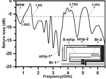
Figure 2 is the return loss of the developed antenna for the case with strip-1 and strip-2. Strip-1 and strip-2 generate resonances at 680 MHz and 850 MHz, respectively. Thus a broadband feature is observed 660–1050 MHz. A parasitic resonance is excited about 2.04 GHz and 2.55 GHz. In the mean time, there are parasitic bands in higher frequencies due to the complicated EMC interaction.
Figure 3 shows the return loss for the developed antenna after two branches (marked Br-1 and Br-2 as shown in Fig. 1(b)) are introduced on the basis of the structure for Fig. 2. The operation bands move to a lower frequency from 1.75 GHz to 1.7 GHz and move to a higher frequency from 3.7 GHz to 3.8 GHz due to the impedance matching of Br-1 and Br-2 as shown in Fig. 2 and Fig. 3.
(b)
(a) (c)
Figure 1. (a) The geometry of the proposed antenna. (b) Front side. (c) Back side.
Figure 2. Return loss simulated when there is only a strip-1 coupling with a strip-2.
Figure 3. Return loss simulated with added Br-1 and Br-2 on the basis of the Fig. 2.
(a) (b)
Figure 5. The prototype of the multifunctional planar antenna: (a) Top view. (b) Bottom view.
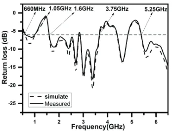
Figure 6. Measured return loss compared to simulated result for the multi-functional planar antenna.
(b) 2.2 GHz
(c) 3.5 GHz
(d) 5.4 GHz
Figure 7. Measured and simulated radiation patterns of the multi-broadband planar antenna at (a) 800 MHz, (b) 2.2 GHz, (c) 3.5 GHz, and (d) 5.4 GHz.
Figure 8. Simulated and measured peak gain of the antenna.
4. CONCLUSION
Antennas Propag., Vol. 57, No. 9, 2541–2547, Sep. 2009.
3. Hong, S., W. Kim, H. Park, S. Kahng, and J. Choi, “Design of an internal multi-resonant monopole antenna for GSM900/DCS1800/US-PCS/S-DMB,”IEEE Trans. Antennas Propag., Vol. 56, No. 5, 1437–1443, May 2008.
4. Wong, K.-L. and C.-H. Huang, “Printed loop antenna with a perpendicular feed for penta-band mobile phone antenna,” IEEE Trans. Antennas Propag., Vol. 56, No. 7, 2138–2141, Jul. 2008. 5. Chang, C.-H. and K.-L. Wong, “Printed/8-PIFA for penta-band WWAN operation in mobile
phone,”IEEE Trans. Antennas Propag., Vol. 57, No. 5, 1373–1381, May 2009.
6. Zheng, M., H. Wang, and Y. Hao, “Internal hexa-band folded monopole/dipole/loop antenna with four resonances for mobile device,” IEEE Trans. Antennas Propag., Vol. 60, No. 6, 2880–2885, Jun. 2012.
7. Zhang, T., R. L. Li, G. P. Jin, G. Wei, and M. M. Tentzeris, “A novel multiband planar antenna for GSM/UMTS/LTE/Zigbee/RFID mobile devices,”IEEE Trans. Antennas Propag., Vol. 59, No. 11, 4209–4214, Nov. 2011.
8. Liu, H. J., R. L. Li, Y. Pan, X. L. Quan, L. Yang, and L. Zheng, “A multi-broadband planar antenna for GSM/UMTS/LTE and WLAN/WiMAX handsets,” IEEE Trans. Antennas Propag., Vol. 59, No. 11, 1–5, Feb. 2014.
9. Li, R. L., B. Pan, J. Laskar, and M. M. Tentzeris, “A novel low-profile broadband dual-frequency planar antenna for wireless handsets,”IEEE Trans. Antennas Propag., Vol. 57, No. 9, 1155–1162, Sep. 2008.
10. Lee, C.-T. and K.-L. Wong, “Planar monopole with a coupling feed and an inductive shorting strip for LTE/GSM/UMTS operation in the mobile phone,” IEEE Trans. Antennas Propag., Vol. 58, No. 7, 2479–2483, Jul. 2010.
11. Li, R. L., X. L. Quan, Y. H. Cui, and M. M. Tentzeris, “Directional triple-band planar antenna for WLAN/WiMAX access points,”IET Electronics Letters, Vol. 48, No. 6, 305–306, Mar. 2012. 12. Lee, C.-T. and K.-L. Wong, “Uniplanar printed coupled-fed PIFA with a band-notching slit for
WLAN/WiMAX operation in the laptop computer,” IEEE Trans. Antennas Propag., Vol. 57, No. 4, 1252–1258, Apr. 2009.
13. Lu, J.-H. and B.-J. Huang, “Planar compact slot antenna with multi-band operation for IEEE 802.16m application,” IEEE Trans. Antennas Propag., Vol. 61, No. 3, 1411–1414, Apr. 2013. 14. Bhatti, R. A., Y.-T. Im, and S.-O. Park, “Compact PIFA for mobile terminals supporting multiple
cellular and non-cellular standards,” IEEE Trans. Antennas Propag., Vol. 57, No. 9, 2534–2540, Sep. 2009.
15. Chen, S.-C. and K.-L. Wong, “Small-size 11-band LTE/WWAN/WLAN internal mobile phone antenna,” Microw. Opt. Technol. Lett., Vol. 52, No. 11, 2603–2608, Nov. 2010.
16. Wong, K.-L., W.-Y. Chen, and T.-W. Kang, “On-board printed coupled-fed loop antenna in close proximity to the surrounding ground plane for penta-band WWAN mobile phone,” IEEE Trans.
Antennas Propag., Vol. 59, No. 3751–757, Mar. 2011.