Study of the Calculation Method of Shielding Effectiveness
of Rectangle Enclosure with an Electrically Large Aperture
Pu-Yu Hu* and Xiao-Ying Sun
Abstract—An analytical model based on the Bethe’s theory of diffraction by small holes is presented to predict the shielding effectiveness (SE) of metallic rectangular enclosure with electrically large aperture under plane wave illumination over a wide frequency range (0 ∼3 GHz). In this model, the aperture is represented as electric and magnetic dipoles located at the center of the aperture, and the coupling relation between external plane wave and electromagnetic field inside the enclosure is established. The approximate solution of electromagnetic field distribution inside the enclosure is obtained in terms of the integrals of the electric and magnetic dynamic Green function. Finally, the influence of enclosure thickness on SE is calculated by introducing thickness attenuation coefficient. The model considers the effect of the thickness on the calculation results and is simple with low computation complex and high estimation accuracy. Besides, the effects of parameters like enclosure and aperture dimensions, aperture and observation point positions, incident and polarization direction of the plane wave on SE can be analyzed comprehensively based on the model. Simulation results of the proposed model are in accord with that of the TLM method, which verifies the accuracy and reliability of the model.
1. INTRODUCTION
With the requirements of practical application such as electric connection, ventilation and cooling, generally there are apertures on the metallic shielding enclosure, which significantly degrades the shielding performance of the enclosure. Therefore, it is of great practical significance to find an appropriate computational method to calculate the SE of an enclosure with aperture quickly and accurately. At present, the calculation methods for SE of shielding enclosure mainly include two major categories: numerical methods and analytical formulations. Numerical methods mainly include the transmission line matrix (TLM) method [1], the method of moments (MOM) [2], the finite-difference time-domain method (FDTD) [3] and so on, which can deal with complex structures with high computational accuracy, but high computational cost and memory requirements. For analytical formulations, there are many simplifications and approximations in the calculation process. Nevertheless, the methods have the dominant advantages of clearer physical meaning and higher efficiency for the computation, which are more appropriate for practical engineering.
One of the representative analytical formulations is proposed by Robinson et al. based on transmission line model [4]. In this method, the rectangular enclosure is modeled by a short-circuited rectangular waveguide and the aperture is represented by a coplanar strip transmission line. However, the method can only handle the cases that i) the incident plane wave has one polarization and direction of travel, ii) the aperture positioned centrally in the front panel of the enclosure, iii) the observation point positioned at the central axis of the enclosure, iv) only the fundamental propagation mode is considered. Thus a great deal of work has been done to improve Robinson’s model, which can solve the problem of oblique plane wave incidence direction, arbitrary aperture position, arbitrary observation
Received 11 August 2017, Accepted 7 October 2017, Scheduled 22 October 2017
* Corresponding author: Pu-Yu Hu ([email protected]).
point position, multiple sides apertures, inner windows and multi-mode condition [5–13]. However, these methods cannot solve the problem of electrically large aperture. Another analytical formulation is proposed based on the Bethe’s theory of diffraction by small holes. These methods have a clearer physical meaning for the aperture coupling process. Nevertheless, the classical Bethe’s theory is also limited to small apertures. Cohn proposed a modified Bethe’s theory to study the coupling of two waveguides by a large aperture in a common wall [17]. Solin studied the analytical formulations of SE of enclosure with electrically small and electrically large aperture based on the modified Bethe’s and waveguide theory, and the calculation results of the formula are in good agreement with that of TLM method [14, 15]. But the model of Solin requires a lot of multiple summation procedures, which showed high computational complexity. Meanwhile, the effect of the thickness on the calculation is not considered in Solin’s model. It means that if the enclosure thickness is large enough, Solin’s model will result in large calculation errors.
An analytical model based on the modified Bethe’s theory is presented in this paper to predict the SE of metallic rectangular enclosure with electrically large aperture under plane wave illumination. The model considers the effect of the thickness on the calculation results and is simple with low computation complex and high estimation accuracy. Besides, the effects of parameters such as the elevation, azimuth and polarization angles of the plane wave, enclosure and aperture dimensions, aperture and observation point position as well as the higher order modes on SE can be taken into account comprehensively. Simulation results of the proposed model are in accord with that of the TLM method, which verifies the accuracy and reliability of the model.
2. ANALYTICAL MODEL
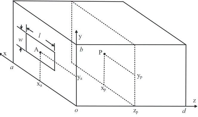
As shown in Fig. 1, the proposed model consists of a rectangular enclosure with an aperture. The dimensions of the rectangular enclosure are a×b×d with thickness of t and the dimension of the rectangular aperture isl×w, the center point of the aperture is located at A(xa, ya,0). The arbitrary
SE observation point is located atP(xp, yp, zp) within the enclosure. The incident plane wave propagates
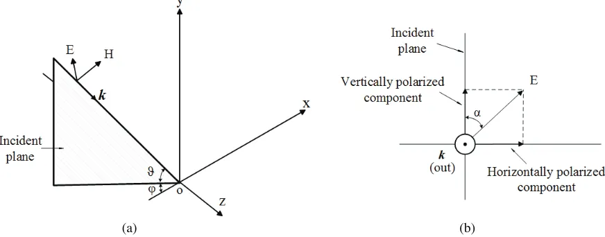
along arbitrary incident direction with arbitrary polarization direction shown in Fig. 2, where ϕis the azimuth angle,ϑ the elevation angle, and α the polarization angle.
x
z y
w l
A P
xa
ya yp
xp
d
o zp
a
b
Figure 1. Geometry of an enclosure with an aperture.
2.1. Plane Wave Decomposition
The electric field vector at any point in free space can be described as
(a) (b)
Figure 2. Sketch map of plane wave radiation. (a) Wave vector; (b) Polarization.
whereE0 is the electric field amplitude, and the electric field vectorE can be converted from spherical
coordinates with azimuth angle, elevation angle and polarization angle
Ex = E0sinαsinϕ+ cosαcosϕsinϑ (2a)
Ey = E0cosαcosϑ (2b)
Ez = E0cosαsinϕsinϑ−sinαcosϕ (2c)
the wave vector k is determined by azimuth angle and elevation angle
kx = kcosϑcosϕ (3a)
ky = −ksinϑ (3b)
kz = kcosϑsinϕ (3c)
the relation between the magnetic field vector and electric field vector is expressed as
H= 1
ηk×E (4)
whereη is the wave impedance. Therefore,H can be written as follows
Hx = 1
η(−Eycosϑsinϕ−Ezsinϑ) (5a)
Hy = 1
η(Excosϑsinϕ−Ezcosϑcosϕ) (5b)
Hz = 1
η(Eycosϑcosϕ+Exsinϑ) (5c)
2.2. SE Calculation for Rectangular Enclosure with Aperture
According to Bethe’s theory, the aperture can be represented as electric and magnetic dipoles located at the center of the aperture. The electric dipole p is normal to the plane of the aperture, and the magnetic dipolemis parallel to the plane of the aperture. Dipole strength is determined by the incident field and the characteristics of the aperture, and p andmare given by [16]
p = χαeε0ESCzˆz (6)
m = −χαmxHSCxxˆ−χαmyHSCyyˆ (7)
where ε0 is the dielectric constant. It is worth noting that classical Bethe’s theory is limited to
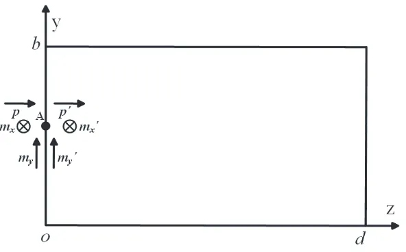
Figure 3. Side view of enclosure with dipole located at both side of the aperture.
is introduced to modifyp and m. Fortinfinitesimal andlw,χ= 1/(1−(kl/π)2) [15, 17]. ESC and HSC are the short circuited electric field and magnetic field at the perfectly electric conducting surface in the absence of the aperture, which can be expressed as [18]
ESCz = 2Ez (8a)
HSCx = 2Hx (8b)
HSCy = 2Hy (8c)
the magnetic polarizabilities αmx,αmy and electric polarizabilities αe depend on the shape and size of the aperture. For a slot as shown in Fig. 1, the polarizabilities are given by [14, 19–21]
αe = −πw2l1−0.5663w/l+ 0.1398w2/l2/16 (9)
αmx = 0.132l3/ln (1 + 0.66l/w) (10)
αmy = πw2l(1 + 0.3221w/l)/16 (11)
The dipoles are located on both sides of the perfectly electric conducting surface which fill the aperture. The mand p radiate into half-space from where the plane wave is incident. In front of the other side of perfectly electric conducting surface, mirrored dipoles m and p, oriented in the same direction as
m and p, radiate into completely closed metallic enclosure, and the size of m and p is the same as that of m and p [22], as shown in Fig. 3. The field in the enclosure excited by m and p can be equivalent to the interior field excited by external plane wave incident on the aperture. The electric field E and magnetic field H in a rectangle enclosure contributed by the electric current distributions J and magnetic current distributions M inside the enclosure can be represented as [23]
E(r) = −jωμ0
V
¯
Ge1(r, r)J(r)dV−
V
∇ ×G¯e2(r, r)M(r)dV (12)
H(r) =
V
∇ ×G¯e1(r, r)J(r)dV−jωε
0
V
¯
Ge2(r, r)M(r)dV (13)
where μ0 is the permeability of the medium; r and r are the position vectors of the field and the
source point, respectively; ¯Ge1 and ¯Ge2 are the dyadic Green’s functions of the first and second kinds,
respectively; V is the volume which sources occupy.
Therefore, the induced electric field components at arbitrary point P(x, y, z) inside a rectangle enclosure due to the ˆz-direction electric dipole located at the aperture position A(xa, ya,0) are given by [16]
Eez(x, y, z) = −ε0mε0njωμ0(jωp )
k2(ab)
∞
m=0
∞
n=0
Γmn kmn
cos (kmn(z−d))
Eey(x, y, z) = −ε0mε0njωμ0(jωp )
k2(ab)
∞ m=0 ∞ n=0
Γmnsin (kmn(d−z))
sin (kmnd) (14b)
Eex(x, y, z) = −ε0mε0njωμ0(jωp
)
k2(ab)
∞ m=0 ∞ n=0
Γmnsin (kmn(d−z))
sin (kmnd) (14c)
where
kmn = k2−(mπ/a)2−(nπ/b)2 (15)
Γmn =
mπ a 2 + nπ b 2 sin mπx a a sin nπy a b sin mπx a sin nπy b (16)
Γmn =
nπ b sin mπx a a sin nπy a b sin mπx a cos nπy b (17)
Γmn =
mπ a sin mπx a a sin nπy a b cos mπx a sin nπy b (18)
Neumann factorsε0m and ε0n are given by
ε0m =
0, m= 0
2, m= 0 (19a)
ε0n =
1, n= 0
2, n= 0 (19b)
The induced electric field components due to the ˆx-direction magnetic dipole located at the aperture positionA(xa, ya,0) are given by [24, 25]
Emxz(x, y, z) = ε0mε0njωμ0m
x ab ∞ m=0 ∞ n=0
ΓMNx kmn
cos (kmn(z−d))
sin (kmnd) (20a)
Emxy(x, y, z) = ε0mε0njωμ0m
x ab ∞ m=0 ∞ n=0
ΓMNxsin (kmn(d−z))
sin (kmnd) (20b)
Emxx(x, y, z) = 0 (20c)
where
ΓMNx = nπ b sin mπx a a cos nπy a b sin mπx a sin nπy b (21)
ΓMNx = sin
mπx a a cos nπy a b sin mπx a cos nπy b (22)
Similarly, the induced electric field components due to the ˆy-direction magnetic dipole located at the aperture position A(xa, ya,0) are given by
Emyz(x, y, z) = ε0mε0njωμ0m
y ab ∞ m=0 ∞ n=0
ΓMNy
kmn
cos (kmn (z−d))
sin (kmn d) (23a)
Emyy(x, y, z) = 0 (23b)
Emyx(x, y, z) = ε0mε0njωμ0m y ab ∞ m=0 ∞ n=0
ΓMNysin (k
mn(d−z))
sin (kmnd) (23c)
where
kmn = k2−(nπ/a)2−(mπ/b)2 (24)
ΓMNy = nπ a sin mπy a b cos nπx a a sin mπy b sin nπx a (25)
ΓMNy = sin
The total electric field components at observation point can be obtained by
Ex(xp, yp, zp) = Eex(xp, yp, zp) +Emxx(xp, yp, zp) +Emyx(xp, yp, zp) (27a)
Ey(xp, yp, zp) = Eey(xp, yp, zp) +Emxy(xp, yp, zp) +Emyy(xp, yp, zp) (27b) Ez(xp, yp, zp) = Eez(xp, yp, zp) +Emxz(xp, yp, zp) +Emyz(xp, yp, zp) (27c)
The total electric field and SE at observation point are
EP =
(Ex)2+ (E
y)2+ (E
z)2 (28)
SE0 = −20 log10|EP/E0| (29)
2.3. Thickness Correction
The enclosure thickness is also an important parameter affecting shielding effectiveness. When the enclosure thickness is large enough, the effect of the thickness on the calculation results cannot be ignored. The literature [17] divides the attenuation of aperture to electromagnetic field into two parts, one of which is the attenuation introduced by the thickness of the aperture. The attenuation of the aperture thickness can be equivalent to the attenuation of the principal mode in a waveguide whose cross section is the shape and size of the aperture, and whose length is equal to the thickness. Therefore, this method is used here to calculate the influence of enclosure thickness on SE. For an enclosure of finite thickness t, attenuation coefficient at (in dB) is introduced to describe the attenuation process,
which is expressed as
at= 54.6tA λc
1−
λc
λ 2
(30)
where A is the coefficient related to thickness. Here we set the parameterA to 1 approximately. λc is
the waveguide cutoff wavelength. Finally, the modified SE is expressed as
SE =SE0+at (31)
3. SIMULATION RESULTS AND ANALYSIS
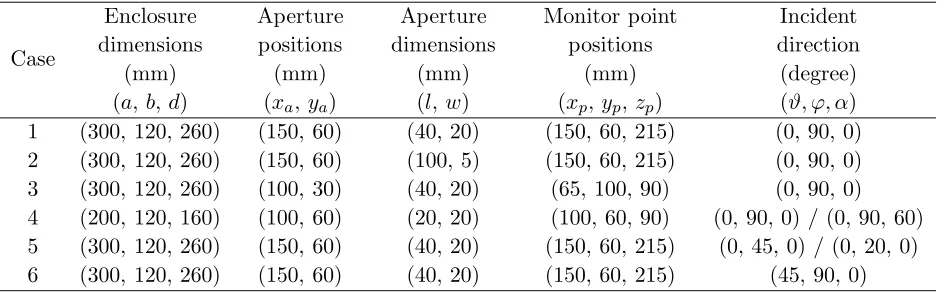
In this section, the simulation results of the proposed model are compared with those of the TLM using CST-MS software. Simulation parameters are set as: the rectangle enclosure material is aluminum with conductivity of 3.56×10⁷S/m; the thickness of the enclosure is 1 mm; the plane wave excitation signal is a Gaussian signal; the frequency range is 0 ∼ 3 GHz. Six cases are considered to verify the validity of the model, with the specific parameters such as enclosure dimensions, aperture dimensions and positions, observation point positions, incident and polarization direction of the plane wave shown in Table 1.
Table 1. Specific parameter settings.
Case
Enclosure dimensions
(mm) (a,b,d)
Aperture positions
(mm) (xa,ya)
Aperture dimensions
(mm) (l,w)
Monitor point positions
(mm) (xp,yp,zp)
Incident direction
In order to analyze the resonant characteristics of the enclosure, formulas for calculating resonant frequencies of rectangular waveguide enclosure are given by
fmnh= 2 c
π√μ0ε0
mπ
a
2
+
nπ
b
2
+
hπ d
2
(32)
wherec is the velocity of light.
For case 1, the aperture is positioned centrally in the front panel of the enclosure, and the observation point is located at the central axis of the enclosure. The simulation results of the presented model, the model of literature and TLM method are shown in Fig. 4. It can be seen from the figure that the SE result of the proposed model is in good agreement with that of TLM method. Comparing the results of literature [4], the proposed model takes into account the high-order mode, and can accurately calculate the SE of the enclosure in high frequency band.
TE101 TE102 TE301
TE103 TE302
TE104 TE303
Figure 4. SE result of case 1.
For case 2, the aspect ratio of the aperture (l = 100mm, w = 5 mm) is far greater than 1. The simulation results of the presented model, the model of Solin [15] and TLM method are shown in Fig. 5. It can be seen from the figure that the SE result of the proposed model is in good agreement with that of TLM method. Besides, the SE result of the Solin’s model is also in good agreement with that of TLM method. The comparison shows that the result of the presented model is more accuracy than that of the Solin’s model in the low frequency band. And the model of Solin requires a lot of multiple summation procedures, which showed higher computational complexity than the model proposed in this
paper. Meanwhile, the effect of the thickness on the calculation is not considered in Solin’s model, it means that if the enclosure thickness is large enough, Solin’s model will result in large calculation errors. The influence of the enclosure thickness on the SE calculated by the model proposed in the paper is shown in Fig. 6.
Figure 6. The influence of the enclosure thickness on the SE.
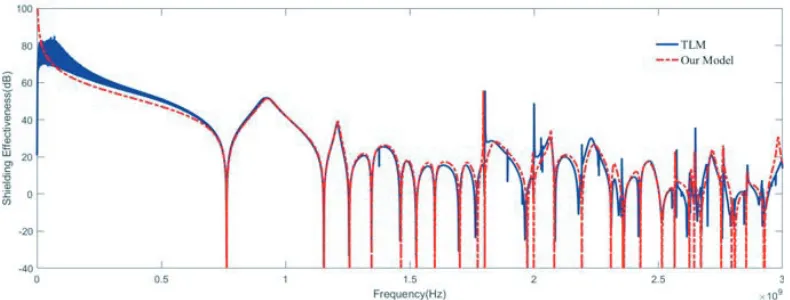
Unlike cases 1 and 2, off-axis observation point and off-centered aperture are considered in case 3. The simulation results of the proposed model and TLM method are shown in Fig. 7. It can be seen from the figure that the SE result of the presented model and TLM method coincide with each other well. The resonant points introduced because of the change of aperture position can be calculated accurately.
Figure 7. SE result of case 3.
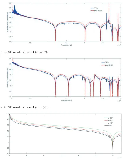
For case 4, the size of the enclosure, aperture and polarization angle are changed. The enclosure dimensions area= 200 mm,b= 120 mm,d= 160 mm, and the aperture dimensions arel=w= 20 mm. The polarization angles of the plane wave are 0 and 60 degrees, respectively with the plane wave normally incident. The simulation results of the proposed model and TLM method are shown in Fig. 8 and Fig. 9. The figures show that the result of the proposed model is in good agreement with that of TLM method. The change of polarization angle leads to the introduction of resonance points such as T E011 around
Figure 8. SE result of case 4 (α= 0◦).
Figure 9. SE result of case 4 (α= 60◦).
Figure 10. The influence of polarization angle on SE.
Figure 11. SE result of case 5 obtained by TLM method.
Figure 12. SE result of case 5 obtained by the presented model.
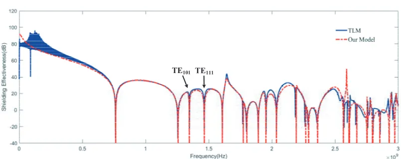
TE101 TE111
Figure 13. SE result of case 6.
of resonance points such as T E101 and T E111 around 1.5 GHz. This is a result of the excitation of the
ˆ
z-direction equivalent electric dipole. The SE at these resonant point will drop drastically, which will affect the shielding performance of the enclosure.
4. CONCLUSIONS
An analytical model based on the modified Bethe’s theory to predict the SE of enclosure with aperture is presented in this paper. The model takes into account various parameters such as enclosure thickness as well as enclosure and aperture dimensions, aperture and observation point positions, incident and polarization direction of the plane wave. By this model, the SE of the enclosures under plane wave illumination can be calculated accurately with low computation complex over a wide frequency range (0 ∼ 3 G). Several cases are presented to demonstrate the validity and accuracy of the model, and analyze the effect of the azimuth, elevation and polarization angle on SE thoroughly. The calculation results of the model are in good agreement with that of CST simulation software using TLM method.
REFERENCES
1. Carpes, Jr, W. P., et al., “TLM and FEM methods applied in the analysis of electromagnetic coupling,”IEEE Transactions on Magnetics, Vol. 36, No. 4, 982–985, 2000.
2. Dehkhoda, P., A. Tavakoli, and M. Azadifar, “Shielding effectiveness of an enclosure with finite wall thickness and perforated opposing walls at oblique incidence and arbitrary polarization by GMMoM,” IEEE Transactions on Electromagnetic Compatibility, Vol. 54, No. 4, 792–805, 2012. 3. Jiao, C., et al., “Subcell FDTD analysis of shielding effectiveness of a thin-walled enclosure with
an aperture,”IEEE Transactions on Magnetics, Vol. 42, No. 4, 1075–1078, 2006.
4. Robinson, M. P., et al., “Shielding effectiveness of a rectangular enclosure with a rectangular aperture,” Electronics Letters, Vol. 32, No. 17, 1559–1560, 1996.
5. Po’Ad, F. A., et al., “Analytical and experimental study of the shielding effectiveness of a metallic enclosure with off-centered apertures,” International Zurich Symposium on Electromagnetic Compatibility, 2006, Emc-Zurich, 618–621, IEEE Xplore, 2006.
6. Dan, S., Y. Shen, and Y. Gao, “3 high-order mode transmission line model of enclosure with off-center aperture,” International Symposium on Electromagnetic Compatibility, 361–364, IEEE, 2007.
7. Nie, B. L. and P. A. Du, “An efficient and reliable circuit model for the shielding effectiveness prediction of an enclosure with an aperture,”IEEE Transactions on Electromagnetic Compatibility, Vol. 57, No. 3, 357–364, 2015.
8. Liu, E., P. A. Du, and B. Nie, “An extended analytical formulation for fast prediction of shielding effectiveness of an enclosure at different observation points with an off-axis aperture,” IEEE Transactions on Electromagnetic Compatibility, Vol. 56, No. 3, 589–598, 2014.
9. Azaro, R., et al., “A circuital approach to evaluating the electromagnetic field on rectangular apertures backed by rectangular cavities,”IEEE Transactions on Microwave Theory&Techniques, Vol. 50, No. 10, 2259–2266, 2002.
10. Konefal, T., et al., “A fast multiple mode intermediate level circuit model for the prediction of shielding effectiveness of a rectangular box containing a rectangular aperture,”IEEE Transactions on Electromagnetic Compatibility, Vol. 47, No. 4, 678–691, 2006.
11. Yin, M. C. and P. A. Du, “An improved circuit model for the prediction of the shielding effectiveness and resonances of an enclosure with apertures,”IEEE Transactions on Electromagnetic Compatibility, Vol. 58, No. 2, 448–456, 2016.
13. Hao, J.-H., P.-H. Qi, J.-Q. Fan, and Y.-Q. Guo, “Analysis of shielding effectiveness of enclosures with apertures and inner windows with TLM,”Progress In Electromagnetic Research M, Vol. 32, 73–82, 2013.
14. Solin, J. R., “Formula for the field excited in a rectangular cavity with a small aperture,” IEEE Transactions on Electromagnetic Compatibility, Vol. 53, No. 1, 82–90, 2011.
15. Solin, J. R., “Formula for the field excited in a rectangular cavity with an electrically large aperture,” IEEE Transactions on Electromagnetic Compatibility, Vol. 54, No. 1, 188–192, 2012. 16. Tesche, F. M., M. V. Ianoz, and T. Karlsson,EMC Analysis Methods and Computational Models,
Wiley, 1997.
17. Cohn, S. B., “Microwave coupling by large apertures,” Proceedings of the IRE, Vol. 40, No. 6, 696–699, 1952.
18. Pozar, D. M., Microwave Engineering, Academic, 2006.
19. Mcdonald, N. A., “Polynomial approximations for the electric polarizabilities of some small apertures,” IEEE Xplore, Vol. 33, No. 11, 1146–1149, 1985.
20. Mcdonald, N. A., “Polynomial approximations for the transverse magnetic polarizabilities of some small apertures,” IEEE Transactions on Microwave Theory & Techniques, Vol. 35, No. 1, 20–23, 2003.
21. Mcdonald, N. A., “Simple approximations for the longitudinal magnetic polarizabilities of some small apertures,” IEEE Transactions on Microwave Theory & Techniques, Vol. 36, No. 7, 1141– 1144, 2002.
22. Nitsch, J. B., S. V. Tkachenko, and S. Potthast, “Transient excitation of rectangular resonators through electrically small circular holes,” IEEE Transactions on Electromagnetic Compatibility, Vol. 54, No. 6, 1252–1259, 2012.
23. Li, L. W., et al., “On the eigenfunction expansion of electromagnetic dyadic Green’s functions in rectangular cavities and waveguides,” IEEE Transactions on Microwave Theory & Techniques, Vol. 43, No. 3, 700–702, 1995.
24. Crawhall, R. J. H.,EMI Potential of Multiple Sources within a Shielded Enclosure, 1993.