Volume 2008, Article ID 469698,13pages doi:10.1155/2008/469698
Research Article
Integrating Illumination, Motion, and Shape Models
for Robust Face Recognition in Video
Yilei Xu, Amit Roy-Chowdhury, and Keyur Patel
Department of Electrical Engineering, University of California, Riverside, CA 92521, USA
Correspondence should be addressed to Amit Roy-Chowdhury,[email protected]
Received 30 April 2007; Revised 1 October 2007; Accepted 25 December 2007
Recommended by N. Boulgouris
The use of video sequences for face recognition has been relatively less studied compared to image-based approaches. In this paper, we present ananalysis-by-synthesisframework for face recognition fromvideo sequencesthat is robust to large changes in facial pose and lighting conditions. This requires tracking the video sequence, as well as recognition algorithms that are able to integrate information over the entire video; we address both these problems. Our method is based on a recently obtained theoretical result that can integrate the effects of motion, lighting, and shape in generating an image using a perspective camera. This result can be used to estimate the pose and structure of the face and the illumination conditions for each frame in a video sequence in the presence of multiple point and extended light sources. We propose a new inverse compositional estimation approach for this purpose. We then synthesize images using the face model estimated from the training data corresponding to the conditions in the probe sequences. Similarity between the synthesized and the probe images is computed using suitable distance measurements. The method can handle situations where the pose and lighting conditions in the training and testing data are completely disjoint. We show detailed performance analysis results and recognition scores on a large video dataset.
Copyright © 2008 Yilei Xu et al. This is an open access article distributed under the Creative Commons Attribution License, which permits unrestricted use, distribution, and reproduction in any medium, provided the original work is properly cited.
1. INTRODUCTION
It is believed by many that video-based facerecognition sys-tems hold promise in certain applications where motion can be usedas a cue for face segmentation and tracking, and the presence of more data can increase recognition performance [1]. However, these systems have their own challenges. They require tracking the video sequence, as well as recognition algorithms that are able to integrate information over the entire video.
In this paper, we present a novel analysis-by-synthesis
framework for pose and illumination invariant, video-based
face recognitionthat is based on (i) learning joint
illumina-tion and moillumina-tion models from video, (ii) synthesizing novel views based on the learned parameters, and (iii) designing measurements that can compare two time sequences while being robust to outliers. We can handle a variety of lighting conditions, including the presence of multiple point and extended light sources, which is natural in outdoor environ-ments (where face recognition performance is still relatively
poor [1–3]). We can also handle gradual and sudden changes of lighting patterns over time. The pose and illumination conditions in the gallery and probe can be completely
disjoint. We show experimentally that our method achieves
high identification rates under extreme changes of pose and illumination.
1.1. Previous work
The proposed approach touches upon aspects of face recog-nition, tracking and illumination modeling. We place our work in the context of only the most relevant ones.
face recognition system given one single image under arbi-trary unknown lighting. Another 3D face morphable model-(3DMM-) based face recognition algorithm was proposed in [5], but they use the Phong illumination model, estimation of those parameters can be more difficult in the presence of multiple and extended light sources. The authors in [6] proposed to use Eigen light-fields and Fisher light-fields to do pose invariant face recognition. The authors in [7] introduced a probabilistic version of Fisher light-fields to handle the differences of face images due to within-individual variability. Another method of learning statistical dependency between image patches was proposed for pose invariant face recognition in [8]. Correlation filters, which analyze the image frequencies, have been proposed for illumination invariant face recognition from still images in [9]. A novel method for multilinear independent component analysis was proposed in [10] for pose and illumination invariant face recognition.
All of the above methods deal with recognition in a single image or across discrete poses and do not consider continuous video sequences. Video-based face recognition requires integrating the tracking, recognition modules, and exploitation of the spatiotemporal coherence in the data. The authors in [11] deal with the issue of video-based face recognition, but concentrate mostly on pose variations. Sim-ilarly, [12] used adaptive hidden Markov models for pose-varying video-based face recognition. The authors of [13] proposed to use a 3D model of the entire head for exploiting features like hairline and handled large pose variations in head tracking and video-based face recognition. However, the application domain is consumer video and requires recognition across a few individuals only. The authors in [14] proposed to perform face recognition by computing the Kullback-Leibler divergence between testing image sets and a learned manifold density. Another work in [15] learns manifolds of face variations for face recognition in video. A method for video-based face verification using correlation filters was proposed in [16], but the poses in the gallery and probe have to be similar.
Except [13] (which is not aimed at face recognition on large datasets), all the rest are 2D approaches, in contrast to our 3D model-based method. The advantage of using 3D models in face recognition has been highlighted in [17], but their focus is on acquiring 3D models directly from the sensors. The main reason for our use of 3D models is invariance to large pose changes and more accurate representation of lighting compared to 2D approaches. We do not need to learn models of appearance under different pose and illumination conditions.This makes our recognition strategy independent of training data needed to learn such models, and allows the gallery and probe conditions to be completely disjoint.
There are numerous methods for tracking objects in video in the presence of illumination changes [18–22]. However, most of them compensate for the illumination conditions of each frame in the video (as opposed to
recovering the illumination conditions). In [23, 24], the
authors independently derived a low order (9D) spherical harmonics-based linear representation to accurately
approxi-mate the reflectance images produced by a Lambertian object with attached shadows. In [24,25], the authors discussed the advantage of this 3D model-based illumination representa-tion compared to some image-based representarepresenta-tions. Their methods work only for a single image of an object that is fixed relative to the camera, and do not account for changes in appearance due to motion. We proposed a framework in [26, 27] for integrating the spherical harmonics-based illumination model with the motion of the objects leading to a bilinear model of lighting and motion parameters. In this paper, we show how the theory can be used for video-based face recognition.
1.2. Overview of the approach
The underlying concept of this paper is a method for learning joint illumination and motion models of objects from video. We assume that a 3D model of each face in the gallery is available. For our experiments, the 3D model is estimated from images, but any 3D modeling algorithm, including directly acquiring the model through range sen-sors, can be used for this purpose. Given a probe sequence, we track the face automatically in the video sequence under arbitrary pose and illumination conditions using the bilinear model of the illumination and motion we developed before [27]. This is achieved by a new inverse compositional esti-mation approach leading to real-time performance [28]. The illumination invariant model-based tracking algorithm allows us not only to estimate the 3D motion, but also to
recover the illumination conditions as a function of time.
The learned illumination parameters are used to synthesize video sequences for each gallery under the motion and illumination conditions in the probe. The distance between the probe and synthesized sequences is then computed for each frame. Different distance measurements are explored for this purpose. Next, the synthesized sequence that is at a minimum distance from the probe sequence is computed and is declared to be the identity of the person.
1.3. Contributions
The following are the main contributions of the paper.
(i) We propose an analysis-by-synthesis framework for video-based face recognition that can work with large pose and illumination changes that are normal in natural imagery.
(ii) We propose a novel, inverse compositional (IC) approach for estimating 3D pose, and lighting condi-tions in the video sequence. Unlike existing methods [30], our warping function involves a 2D→3D →
2D transformation. Our method allows us to estimate the motion and lighting in real-time.
(iii) We propose different metrics to obtain the identity of the individual in a probe sequence by integrating over the entire video and compare their merits and demerits.
(iv) Our overall strategy does not require learning an appearance variation model, unlike many existing methods [10–12,14–16]. Thus, the proposed strategy is not dependent on the quality of the learned appearance model and can handle situations where the pose and illumination conditions in the probe are completely independent of the gallery and training data.
(v) We perform a thorough evaluation of our method against well-known image-based approaches like Kernel PCA + LDA [31] and 3D model-based approaches like 3DMM [4,5].
2. LEARNING JOINT ILLUMINATION AND MOTION MODELS FROM VIDEO
2.1. Bilinear model of the motion and illumination
In this section, we will briefly review the main results in [27] helping to lay the background and notation for this paper. It was proved that if the motion of the object (defined as the translation of the object centroidΔT∈R3and the rotation
ΔΩ∈R3about the centroid in the camera frame) from time
t1to new time instancet2=t1+δtis small, then up to a first
order approximation, the reflectance imageI(x,y) att2can
be expressed as
It2(u)=
9
i=1
libi t2(u), b
i t2(u)
=bit1(u) +A(u,n)ΔT+B(u,n)ΔΩ.
(1)
In the above equations, u represents the image point projected from the 3D surface with surface normal n (see Figure 1), and bit1(u) are the original basis images before
motion.AandBcontain the structure and camera intrinsic parameters, and are functions of u and the 3D surface normal n. For each pixel u, both A and B are Nl × 3 matrices, whereNl≈9 for Lambertian objects with attached shadows. Please refer to [26] for the derivation of (1) and explicit expression for A and B. From (1), we see that
P2
P1
P2 P
1
n2 n1
n2
n1
SurfaceA
SurfaceB
Image plane
Camera/world Reference frame
Illumination
x y
z
Figure1: Pictorial representation showing the motion of the object and its projection (reproduced from [26]).
the new image spans a bilinear space of six motion and approximately nine illumination variables (for Lambertian objects with attached shadows). The basic result is valid for general illumination conditions, but requires consideration of higher order spherical harmonics.
We can express the result in (1) succinctly using tensor notation as
It2=
Bt1+Ct1×2
ΔT
ΔΩ ×1l, (2)
where×nis called themode-n product[32] andl ∈RNl, is the vector oflicomponents. Themode-n productof a tensor
A ∈RI1×I2×···×In×···×IN by a vectorV ∈R1×In, denoted by
A×nV, is theI1×I2× · · · ×1× · · · ×INtensor
A×nV
i1···in−11in+1···iN =
in
ai1···in−1inin+1···iNvin. (3)
For each pixel (p,q) in the image,Ckl pq = [A B] of size Nl×6. Thus for an image of sizeM×N,CisNl×6×M×N. Bt1is a subtensor of dimensionNl×1×M×N, comprising
the basis imagesbi
t1(u), andIt2is a subtensor of dimension
1×1×M×N, representing the image.
2.2. Pose and illumination estimation
Equation (2) provides us an expression relating the reflectance imageIwith the illumination coefficientsland motion variables ΔT, ΔΩ.Letting m = ΔT
ΔΩ
, we have a method for estimating 3D motion and illumination as
lt2,mt2
=arg min l,m
It2−
Bt1+Ct1×2m
×1l2+αm2,
(4)
wherexdenotes an estimate ofx. Since the motion between consecutive frames is small, but illumination can change suddenly, we add a regularization term to the above cost function with the form ofαm2.
Since the imageIt2lies approximately in a bilinear space
Ct1 computed at the pose close to that ofIt2 (ignoring the
regularization term for now), such a minimization problem can be achieved by alternately estimating the motion and illumination parameters with the bases Bt1 andCt1 at the
pose of the previous iteration. This process guarantees con-vergence to a local minimum. Assuming that we have tracked the sequence up to some frame for which we can estimate the motion (hence, pose) and illumination, we calculate the basis images,bit1, at the current pose and write it in tensor
form Bt1. Similarly, we can also obtain Ct1 at the pose.
(Assume anNth-order tensorA∈CI1×I2×···×IN. The matrix
unfolding A(n) ∈ CIn×(In+1In+2···INI1I2···In−1) contains the
ele-mentai1i2···iN at the position with row numberinand column
number equal to (in+1−1)In+2In+3· · ·INI1I2· · ·In−1+(in+2−
1)In+3In+4· · ·INI1I2· · ·In−1+· · ·+ (iN−1)I1I2· · ·In−1+
(i1−1)I2I3· · ·In−1+· · ·+in−1.) UnfoldingBt1and the image
It2along the first dimension, [32] which is the illumination
dimension, the image can be represented as
IT t2(1)=B
T
t1(1)l. (5)
This is a least squares problem, and the illuminationlcan be estimated as
l=Bt1(1)B
T t1(1)
−1
Bt1(1)I
T
t2(1). (6)
Keeping the illumination coefficients fixed, the bilinear space in (2) becomes a linear subspace, that is,
It2=Bt1×1l+G×2m, whereG=Ct1×1l, (7)
and motionmcan be estimated as
m=G(2)GT(2)+αI
−1
G(2)
It2−Bt1×1l
T
(2), (8)
whereIis an identity matrix of dimension 6×6.
2.3. Inverse compositional (IC) pose and illumination estimation
The iteration involving alternate minimization over motion and illumination in the above approach is essentially a gradient descent method. In each iteration, as pose is updated, the gradients (i.e., the tensorsB andC) need to be recomputed, which is computationally expensive. The inverse compositional algorithm [30] works by moving these computational steps out of the iterative updating process.
Consider an input frameIt2(u) at time instancet2with
image coordinate u. We introduce a warp operator Wp :
R2→R2 such that, if the pose of I
t2(u) is p, the pose of
It2(Wp(u,m)) isp+m(seeFigure 2). Basically,Wprepresents
the displacement in the image plane due to a pose transfor-mation of the 3D model. Denote the pose transformed image It2(Wpt1(u,m)) in tensor notationI
Wpt1(m)
t2 . Using this warp
operator and ignoring the regularization term, we can restate the cost function (4) in the inverse compositional framework as
lt2,mt2
=arg min l,m
IWpt1(−m)
t2 −Bt1×1l
2. (9)
3D model
v
v u
Posep It(v)
Posep+Δp
Wp
It(Wp(v,Δp))
Figure 2: Illustration of the warping function W. A pointv in image plane is projected onto the surface of the 3D object model. After the pose transformation withΔp, the point on the surface is back-projected onto the image plane at a new pointu. The warping function maps fromv ∈R2tou∈R2. The red ellipses show the
common part in both frames that the warping functionWis defined upon.
This cost function can be minimized overm by iteratively solving for incrementsΔmin
IWpt1(−m)
t2 −(Bt1+Ct1×2Δm)×1l
2. (10)
In each iteration, m is updated such thatWpt1(u,−m) ←
Wpt1(u,−m)◦Wpt1(u,Δm) −1
.(The compositional operator
◦ means the second warp is composed into the first warp, that is, Wpt1(u,−m) ≡ Wpt1(Wpt1(u,Δm)
−1
,−m.)) (The inverse of the warp W is defined to be the R2→R2
mapping such that if we denote the pose of It(v) as p, the pose of It(Wp(Wp(v,Δp),Δp)−1) is p itself. As the warp Wp(v,Δp) transforms the pose from p to p+ Δp, the inverse Wp(v,Δp)−1 should transform the pose from
p + Δp to p, that is, Wp(v,Δp)−1 = Wp+Δp(v,−Δp). Thus {Wp} is a group.) Using the additivity of pose transformation for smallΔm,Wpt1(Wpt1(u,Δm)
−1,−m) =
Wpt1(Wpt1+Δm(u,−Δm),−m) = Wpt1+Δm(u,−Δm−m) ≈
Wpt1(u,−Δm −m). Thus, the above update is essentially
m←m+Δm.
For the inverse compositional algorithm to be provably equivalent to the Lucas-Kanade algorithm up to a first order approximation ofΔm, the set of warps{Wpt1}must
form a group, that is, every warp Wpt1 must be invertible.
If the change of pose is small enough, the visibility for most of the pixels will remain the same—thusWpt1 can be
considered approximately invertible. However, if the pose change becomes too big, some portion of the object will become invisible after the pose transformation, andWpt1will
no longer be invertible. A detailed proof of convergence is available in [28].
Gpj I Δm(Step 4) I¯(Step 3)
It
It
Wpt−1(St ep2)
Bpj
pj Pose Illumination
Zpj
Figure 3: Pictorial representation of the inverse compositional tracking scheme. Starting with It, we first warp it to It as in Step 2 below. This allows computation of the bases of the joint pose and illumination manifold at the cardinal posepj. Then, we search along the illumination dimension of this manifold to get the illumination estimate that best describesIt. This is Step3. Then, in Step4,Itis projected onto the tangent plane of the manifold where the motion estimates was obtained.
these poses. We call these poses as cardinal poses. All frames that are close to a particular pose pj will use the B and C at that pose, and the warpWpt1 should be performed to
normalize the pose topj. The pictorial representation of the inverse compositional tracking scheme is shown inFigure 3. While most of the existing inverse compositional methods move the expensive update steps out of the iterations for two-frame matching, we go even further and perform these expensive computations only once every few frames. This is by virtue of the fact that we estimate 3D motion.
2.4. The IC pose and illumination estimation algorithm
Consider a sequence of image framesIt,t=0,. . .,N−1. In keeping with standard notation used in tracking, we assume δt=1, and consider two frames attandt−1.
Assume that we know the pose and illumination esti-mates for framet−1, that is,pt−1andlt−1.
Step 1. For the new input frameIt, find the closestpjto the
pose estimates att−1, that is,pt−1. Setmtto be 0.
Step 2. Apply the pose transformation operatorWpt−1to get
the pose normalized version of the frameIWpt−1(pj−pt−1−mt)
t s,
that is,I(Wpt−1(u,pj−pt−1−mt),t).
Step 3. Use
lt=Bpj |t−1B
T pj|t−1
−1
BTpj|t−1I
Wpt−1(pj−pt−1−mt)
t(1) (11)
to estimateltof the pose normalized imageI
Wpt−1(pj−pt−1−mt)
t .
Step 4. With the estimatedltfrom Step3, use
Δm =GpjG T pj
−1
Gpj I
Wpt−1(pj−pt−1−mt)
t −Bpj|t−1×1lt
(12)
to estimate the motion incrementΔm, where
Gpj=Cpj|t−1×1lt. (13)
Updatemtwithmt ←mt+Δm.
Step 5. Repeat Steps 2, 3, and 4 for that input frame
till the difference error ε between the pose normalized image IWpt−1(pj−pt−1−mt)
t and the rendered image (Bpj|t−1 +
Cpj|t−1×2mt)×1ltcan be reduced below an acceptable
thresh-old. This givesltandmtof (4).
Step 6. Sett=t+ 1. Repeat Steps1,2,3,4, and5. Continue
tillt=N−1.
3. FACE RECOGNITION FROM VIDEO
We now explain the face recognition algorithm and analyze the importance of different measurements for integrating the recognition performance over a video sequence. In our method, the gallery is represented by a textured 3D model of the face. The model can be built from a single image [33], a video sequence [34] or obtained directly from 3D sensors [17]. In our experiments, the face model will be estimated from a gallery video sequence for each individual. Face texture is obtained by normalizing the illumination of the first frame in the gallery sequence to an ambient condition, and mapping it onto the 3D model. Given a probe sequence, we will estimate the motion and illumination conditions using the algorithms described inSection 2.2. Note that the tracking does not require a person-specific 3D model—a generic face model is usually sufficient. Given the motion and illumination estimates, we will then render images from the 3D models in the gallery. The rendered images can then be compared with the images in the probe sequence. For this purpose, we will design robust measurements for comparing these two sequences. A feature of these measurements will be their ability to integrate the identity over all the frames, ignoring some frames that may have the wrong identity.
LetIi,i=0,. . .,N−1 be theith frame from the probe sequence. Let Si,j,i = 0,. . .,N −1 be the frames of the
synthesized sequence for individual j, where j = 1,. . .,M and M is the total number of individuals in the gallery. Note that the number of frames in the two sequences to be compared will always be the same in our method. By design, each corresponding frame in the two sequences will be under the same pose and illumination conditions, dictated by the accuracy of the estimates of these parameters from the probes sequences. Letdi jbe the Euclidean distance between the ith framesIi andSi,j. We now compare three distance
measures that can be used for obtaining the identity of the probe sequence:
(1) ID=arg min
j mini di j, (14)
(2) ID=arg min
j maxi di j, (15)
(3) ID=arg min j
1 N
i
(a) (b) (c)
Figure4: The back projection of the feature points on the generated 3D face model using the estimated 3D motion onto some input frames.
The first alternative computes the distance between the frames in the probe sequence and each synthesized sequence that are the most similar and chooses the identity as the individual with the smallest distance. The second distance measure can be interpreted as minimizing the maximum separation between the frames in the probe sequence and synthesized sequences. Both of these measures suffer from a lack of robustness, which can be critical for their perfor-mance since the correctness of the frames in the synthesized sequences depends upon the accuracy of the illumination and motion parameter estimates. For this purpose, we replace the max by the fth percentile and the min (in the inner distance computation of 1) by the (1−f)th percentile. In our experiments, we choose f to be 0.8.
The third option (16) chooses the identity as the min-imum mean distance between the frames in the probe sequence and each synthesized sequence. Under the assump-tions of Gaussian noise and uncorrelatedness between frames, this can be interpreted as choosing the identity with the maximum a-posterior probability given the probe sequence.
As the images in the synthesized sequences are pose and illumination normalized to the ones in the probe sequence,di j can be computed directly using the Euclidean distance. Other distance measurements, like [14, 35], can be considered in situations where the pose and illumination estimates may not be reliable or in the presence of occlusion and clutter. We will look into such issues in our future work.
3.1. Video-based face recognition algorithm
Using the above notation, letIi,i=0,. . .,N−1 beNframes from the probe sequence. LetG1,. . .,GMbe the 3D models with texture for each ofMgalleries.
Step 1. Register a 3D generic face model to the first
frame of the probe sequence. This is achieved using the method in [36]. Estimate the illumination and motion model parameters for each frame of the probe sequence using the method described inSection 2.4
Step 2. Using the estimated illumination and motion
param-eters, synthesize, for each gallery, a video sequence using the generative model of (1). Denote these asSi,j,i = 1,. . .,N
andj=1,. . .,M.
Step 3. Computedi jas above.
Step 4. Obtain the identity using a suitable distance measure
as in (14) or (15) or (16).
4. EXPERIMENTAL RESULTS
4.1. Accuracy of tracking and illumination estimation
We will first show some results on the accuracy of tracking and illumination estimation with known ground truth. This is because of the critical importance of this step in our proposed recognition scheme. We use the 3DMM [33] to generate a face. The generated face model is rotated along the vertical axis at some specific angular velocity, and the illumination is changing both in direction (from right-bottom corner to the left-top corner) and in brightness (from dark to bright to dark). In Figure 4, the images show the back projection of some feature points on the 3D model onto the input frames using the estimated motion under three different illumination conditions. InFigure 5, (a) shows the comparison between the estimated motion (in blue) and the ground truth (in red). The maximum error in pose estimates is 2.53◦and the average error is 0.67◦.Figure 5(b)shows the norm of the error between the ground truth illumination coefficients and the estimated ones, normalized with the ground truth. The maximum error is 4.93% and the average is 4.1%.
The results on tracking and synthesis on two of the probe sequences in our database (described next) are shown in Figure 6. The inverse compositional tracking algorithm can track about 20 frames per second on a standard PC using a MATLAB implementation. Real-time tracking could be achieved through better software and hardware optimization.
4.2. Face database and experimental setup
−5 0 5 10 15 20 25 30 35 40 45
Estimat
ed
ang
le
about
the
ve
rt
ical
axis
(deg
re
e)
0 20 40 60 80 100 120 140 160
Frame (a)
0.03 0.035 0.04 0.045 0.05 0.055 0.06 0.065 0.07
Il
luminat
ion
est
imat
es
n
or
malize
d
er
ror
(%)
0 20 40 60 80 100 120 140 160
Frame (b)
Figure 5: (a) 3D estimates (blue) and ground truth (red) of pose against frames. (b) The normalized error of the illumination estimates versus frame numbers.
of the first frame in each gallery sequence to an ambient illumination condition and mapping onto the 3D model.
As can be seen fromFigure 7, the pose and illumination vary randomly in the video. For each subject, we designed three experiments by choosing different probe sequences.
Experiment A
A video was used as the probe sequence with the average pose of the face in the video being about 15◦from frontal.
Experiment B
A video was used as the probe sequence with the average pose of the face in the video being about 30◦from frontal.
Figure6: Original images, tracking and synthesis results are shown in three successive rows for two of the probe sequences.
Figure7: Sample frames from the video sequences collected for our database (best viewed on a monitor).
Experiment C
A video was used as the probe sequence with the average pose of the face in the video being about 45◦from frontal.
92 93 94 95 96 97 98 99
100 CMC curve
Id
en
ti
fi
ca
ti
o
n
0 10 20 30 40 50 60
Rank Experiment A Experiment B Experiment C (a)
85 90 95
100 CMC curve
Id
en
ti
fi
ca
ti
o
n
0 10 20 30 40 50 60
Rank Experiment A Experiment B Experiment C (b)
85 90 95
100 CMC curve
Id
en
ti
fi
ca
ti
o
n
0 10 20 30 40 50 60
Rank Experiment A Experiment B Experiment C (c)
Figure8: CMC curve for video-based face recognition experiments A to C; (a) with distance measurement 1 in (14), (b) with distance measurement 2 in (15), and (c) with distance measurement 3 in (16).
4.3. Recognition results
We plot the cumulative match characteristic (CMC) [1,2] for experiments: A, B, and C with measurement 1 (14), measurement 2 (15), and measurement 3 (16) inFigure 8. In experiment A, where pose is 15◦away from frontal, all the videos with large and arbitrary variations of illumination are recognized correctly. In experiment B, we achieve about 95% recognition rate, while for experiment C it is 93% using the distance measure (14). Irrespective of the illumination changes, the recognition rate decreases consistently with large difference in pose from frontal (which is the gallery), a trend that has been reported by other authors [4,5].Note that the pose and illumination conditions in the probe and gallery sets can be completely disjoint.
4.4. Performance analysis
Performance with changing average pose
Figures8(a),8(b), and8(c) show the recognition rate with the measurements in (14), (15), and (16). Measurement 1 in (14) gives the best result. This is consistent with our expectation, as (14) is not affected by the few frames in which the motion and illumination estimation error is relatively high. The recognition result is affected mostly by registration error which increases with nonfrontal pose (i.e., A→B→C). On the other hand, measurement 2 in (15) is mostly affected by the errors in the motion and illumination estimation and registration, and thus the recognition rate in Figure 8(b) is lower than that of Figure 8(a). Ideally, measurement 3 should give the best recognition rate as this is the MAP estimation. However, the assumptions of Gaussianity and uncorrelatedness may not be valid. This affects the recognition rate for measurement 3, causing it perform worse than measurement 1 (14) but better than measurement 2 (15). We also found that small errors in 3D shape estimation have negligible impact on the motion and illumination estimates and the overall recognition result.
Effect of registration and tracking errors
There are two major error sources: registration and motion/ illumination estimation. The error in registration may affect the motion and illumination estimation accuracy in sub-sequent frames, while robust motion and illumination estimation may regain tracking back after some time, if the registration errors are small.
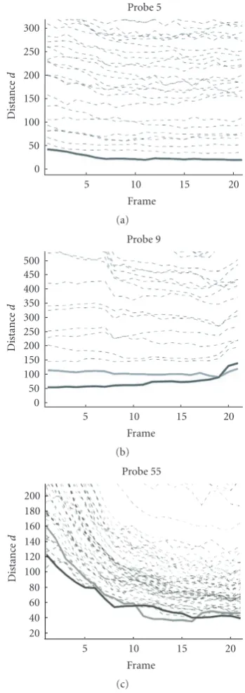
In Figures 9(a), 9(b), and 9(c), we show the plots of error curves under three different cases.Figure 9(a) is the ideal case, in which the registration is accurate and the error in motion and illumination estimation is consistently small through the whole sequence. The distancedikfrom the probe sequenceIiwith the true identitykto the synthesized sequence with the correct modelSi,k, will always be smaller
the distance from the probe sequence to the synthesized sequence with the correct model (shown in bold red) to be higher than some other distance di j, j /=k (shown in green). In this case, measurement 2 in (15) will be wrong but measurements 1 and 3 in (14) or (16) still work. In Figure 9(c), the registration is not accurate (the error dik at the first frame is significantly higher than in (a) and (b)), but the motion and illumination estimation is able to regain tracking after a number of frames where the error decreases. Under this case, both measurements 1 and 2 in (14) and (15) will not work, as it is not any individual frame that reveals the true identity, but the behavior of the error over the collection of all frames. Measurement 3 in (16) computes the overall distance by taking every frame into consideration, thus it works in such cases. This shows the importance of using different distance measurements based on the application scenario. Also, the effect of obtaining the identity by integrating over time is seen.
4.5. Comparison with other approaches
The area of video-based face recognition is less standardized than image-based approaches. There is no standard dataset on which both image and video-based methods have been tried, thus we do the comparison on our own dataset. This dataset can be used for such comparison by other researchers in the future.
Comparison with 3DMM-based approaches
3DMM has achieved a significant impact in the face bio-metrics area, and obtained impressive results in pose and illumination varying face recognition. It is similar to our proposed approach in the sense that both methods are 3D approaches, estimate the pose, illumination, and do synthesis for recognition. However, 3DMM [5] method uses the Phong illumination model, thus it cannot model extended light sources (like the sky) accurately. To overcome this, Samaras and Zhang [4] proposed the 3D shperical harmonics basis morphable model (SHBMM) that integrates the spherical harmonics illumination representation into the 3DMM. Also, 3DMM and SHBMM methods have been applied to single images only. Although it is possible to repeatedly apply 3DMM or SHBMM approach to each frame in the video sequence, it is inefficient. Registration of the 3D model to each frame will be needed, which requires a lot of computation and manual work. None of the existing 3DMM approaches integrate tracking and recognition. Our proposed method, which integrates 3D motion into SHBMM, is a unified approach for modeling lighting and motion in a face video sequence.
Using our dataset, we now compare our proposed approach against the SHBMM method of [4], which was shown, give better results than 3DMM in [5]. We will also compare our results with the published results of SHBMM method [4] in the later part of this section.
Recall that we designed three new experiments: D, E, and F by taking random single images from A, B, and C, respectively. InFigure 10, we plot the CMC curve with
0 50 100 150 200 250 300
Probe 5
Distanc
e
d
5 10 15 20
Frame (a)
0 50 100 150 200 250 300 350 400 450 500
Probe 9
Distanc
e
d
5 10 15 20
Frame (b)
20 40 60 80 100 120 140 160 180 200
Probe 55
Distanc
e
d
5 10 15 20
Frame (c)
Figure9: The plots of error curves under three different cases: (a)
both registration and motion/illumination estimation are correct, (b) registration is correct but motion/illumination estimation has drift error, and (c) registration is inaccurate, but robust motion/illumination estimation can regain tracking after a number of frames. The black, bold curve shows the distance of the probe sequence with the synthesized sequence of the correct identity, while both the gray bold and dotted curves show the distance with the synthesized sequences using the incorrect identity.
94 95 96 97 98 99
100 CMC curve
Id
en
ti
fi
ca
ti
o
n
0 10 20 30 40 50 60
Rank Experiment A Experiment D (a)
91 92 93 94 95 96 97 98 99
100 CMC curve
Id
en
ti
fi
ca
ti
o
n
0 10 20 30 40 50 60
Rank Experiment B Experiment E (b)
84 86 88 90 92 94 96 98
100 CMC curve
Id
en
ti
fi
ca
ti
o
n
0 10 20 30 40 50 60
Rank Experiment C Experiment F (c)
Figure10: Comparison between the CMC curves for the video-based face experiments A to C with distance measurement 1 against SHBMM method of [4].
achieved by integrating spherical harmonics illumination model with the 3DMM (which is essentially the idea in SHBMM [4]) on our data. For this comparison, we randomly chose images from the probe sequences of experiments: A, B, and C and computed the recognition performance over multiple such random sets. Thus the experiments D, E, and F average the image-based performance over different conditions. By analyzing the plots inFigure 10, we see that the recognition performance with the video-based approach is consistently higher than the image-based one, both in rank 1 performance as well as the area under the CMC curve. This trend is magnified as the average facial pose becomes more nonfrontal. Also, we expect that registration errors, in general, will affect image-based methods more than video-based methods (since robust tracking may be able to overcome some of the registration errors, as shown in Section 4.4).
It is interesting to compare these results against the results in [4], for image-based recognition. The size of the databases in both cases is close (though ours is slightly smaller). Our recognition rate with a video sequence at average 15 degrees facial pose (with a range of 15 degrees about the average) is 100%, while the average recognition rate for approximately 20 degrees (called side view) in [4] is 92.4%. For the experiments B and C, [4] does not have comparable cases and goes directly to profile pose (90 degrees), which we do not have. Our recognition rate at 45◦ average pose is 93%. In [4], the quoted rates at 20◦is 92% and at 90◦is 55%. Thus the trend of our video-based recognition results are significantly higher than image-based approaches that deal with both pose and illumination variations.
We would like to emphasize that the above paragraph shows a comparison of recognition rates on two different datasets. While this may not seem completely fair, we are constrained by the lack of a standard dataset on which to compare image- and video-based methods. We have shown a comparison on our dataset using our implementation in Figure 9. The objective of the above paragraph is just to point out some trends with published results on other datasets that do not have video—these should be taken as very definitive statements.
Comparison with 2D approaches
the recognition performance using single frames and the whole video sequences.
When we have a single frame as probe, we use k-Nearest Neighbor for the recognition, while in the case of video sequence, we compute the distance from every frame in the probe sequence to the centroid of the training samples in each class, take the summation over time, and then rank the distance of the sequence to each class. Here, we show the results of recognition with the described 2D approach using single frames and video sequences about 15 degrees (comparable to experiments: A and D), 30 degrees (comparable to experiments: B and E), and 45 degrees (comparable to experiments: C and F) in Figure 11. For the comparison, we also show the results of our approach with video sequences in experiments: A, B, and C. Note that testing frames and sequences are the same as those used in experiments: A/B/C and D/E/F. Since 2D approaches cannot model the pose and illumination variation well, the recognition results are much worse compared to 3D approaches under arbitrary pose and illumination variation. However, we can still see the advantage of integrating the video sequences inFigure 11.
Comparison with 2D illumination methods
The major disadvantage of the 2D illumination methods is that they cannot handle local illumination conditions (lighting coming from some specific direction such that only part of the object is illuminated). In Figure 12, we show the comparison in removing local illumination effects between the spherical harmonics illumination model against the local histogram equalization method. In the three images in Figure 12(a), the top one is the original frame with illumination coming from the left side of the face. The left image in the second row is local histogram equalized, and the right one is resynthesized with the spherical harmonics illumination model with some predefined ambient illumi-nation. In the local histogram equalized image, although the right side of the face is enhanced compared with the original one, the illumination direction can still be clearly perceived. But in the one synthesized with the spherical harmonics illumination model, the direction of illumination is almost completely removed, and no illumination direction information is retained. InFigure 12(b), we show the plot of the error curves of the probe sequence (an image of which is shown inFigure 12(a)) with the local histogram equalization method, while inFigure 12(c)we show the error curves with the method we proposed. It is clear that 3D illumination methods can achieve better results under local illumination conditions.
5. CONCLUSIONS
In this paper, we have proposed an analysis-by-synthesis
method for video-based face recognition that relies upon a novel theoretical framework for integrating illumination motion and shape models for describing the appearance of a video sequence. We started with a brief exposition of this theoretical result, followed by methods for learning
70 75 80 85 90 95
100 CMC curve
Id
en
ti
fi
ca
ti
o
n
0 10 20 30 40 50 60
Rank Experiment A
15 degree video based KPCA/LDA 15 degree single frame based KPCA/LDA
(a)
65 70 75 80 85 90 95 100
CMC curve
Id
en
ti
fi
ca
ti
o
n
0 10 20 30 40 50 60
Rank Experiment B
30 degree video based KPCA/LDA 30 degree single frame based KPCA/LDA
(b)
55 60 65 70 75 80 85 90 95
100 CMC curve
Id
en
ti
fi
ca
ti
o
n
0 10 20 30 40 50 60
Rank Experiment C
45 degree video based KPCA/LDA 45 degree single frame based KPCA/LDA
(c)
(a)
500 550 600 650 700 750 800
Error curve synthesizing using local histogram equalization
Distanc
e
d
5 10 15 20
Frame (b)
0 50 100 150 200
Error curve synthesizing using spherical harmonics illumination model
Distanc
e
d
5 10 15 20
Frame (c)
Figure12: The comparison over local illumination effects between
the spherical harmonics illumination model and the local his-togram equalization method. (a) Top: original image; bottom left: local histogram equalized image; bottom right: synthesis with spherical harmonics illumination model in a predefined ambient illumination. (b) Plots of the error curves using the local histogram equalization. (c) Plots of the error curves using the proposed method. The bold curve is for the face with the correct identity.
the model parameters. Then, we described our recognition algorithm that relies on synthesis of video sequences under the conditions of the probe. We collected a face video
database consisting of 57 people with large and arbitrary variation in pose and illumination and demonstrated the effectiveness of the method on this new database. A detailed analysis of performance is also carried out. Future work on video-based face recognition will require experimentation on large datasets, design of suitable metrics, and tight integration of the tracking and recognition phases.
ACKNOWLEDGMENT
Y. Xu and A. Roy-Chowdhury were supported by NSF Grant IIS-0712253.
REFERENCES
[1] W. Zhao, R. Chellappa, P. J. Phillips, and A. Rosenfeld, Face recognition: a literature survey,ACM Computing Surveys, vol. 35, no. 4, pp. 399458, 2003.
[2] P. J. Phillips, P. J. Grother, R. J. Micheals, D. M. Blackburn, E. Tabassi, and J. M. Bone, Face recognition vendor test 2002: evaluation report,Tech. Rep. NISTIR 6965, National Institute of Standards and Technology, Gaithersburgh, Md, USA, 2003,
http://www.frvt.org/.
[3] P. J. Phillips, P. J. Flynn, T. Scruggs, et al., Overview of the face recognition grand challenge, inProceedings of the IEEE Computer Society Conference on Computer Vision and Pattern Recognition (CVPR ’05), vol. 1, pp. 947954, San Diego, Calif, USA.
[4] L. Zhang and D. Samaras, Face recognition from a single training image under arbitrary unknown lighting using spherical harmonics, IEEE Transactions on Pattern Analysis and Machine Intelligence, vol. 28, no. 3, pp. 351363, 2006. [5] V. Blanz, P. Grother, P. J. Phillips, and T. Vetter, Face
recog-nition based on frontal views generated from non-frontal images, inProceedings of the IEEE Computer Society Conference on Computer Vision and Pattern Recognition (CVPR ’05), vol. 2, pp. 454461, San Diego, Calif, USA.
[6] I. Matthews, R. Gross, and S. Baker, Appearance-based face recognition and light-fields, IEEE Transactions on Pattern Analysis and Machine Intelligence, vol. 26, no. 4, pp. 449465, 2004.
[7] S. Lucey and T. Chen, Learning patch dependencies for improved pose mismatched face verification, inProceedings of the IEEE Computer Society Conference on Computer Vision and Pattern Recognition (CVPR ’06), vol. 1, pp. 909915, New York, NY, USA.
[8] S. J. D. Prince and J. H. Elder, Probabilistic linear discriminant analysis for inferences about identity, inProceedings of the IEEE 11th International Conference on Computer Vision (ICCV ’07), pp. 18, Rio de Janeiro, Brazil, October 2007.
[9] T. Sim, S. Baker, and M. Bsat, The CMU pose, illumination, and expression database,IEEE Transactions on Pattern Analysis and Machine Intelligence, vol. 25, no. 12, pp. 16151618, 2003. [10] M. A. O. Vasilescu and D. Terzopoulos, Multilinear
indepen-dent components analysis, inProceedings of the IEEE Computer Society Conference on Computer Vision and Pattern Recognition (CVPR ’05), vol. 1, pp. 547553, San Diego, Calif, USA. [11] K.-C. Lee, J. Ho, M.-H. Yang, and D. Kriegman, Video-based
[12] X. Liu and T. Chen, Video-based face recognition using adaptive hidden Markov models, in Proceedings of the IEEE Computer Society Conference on Computer Vision and Pattern Recognition (CVPR ’03), vol. 1, pp. 340345, Madison, Wis, USA.
[13] M. Everingham and A. Zisserman, Identifying individuals in video by combinig ‘generative’ and discriminative head mod-els, inProceedings of the 10th IEEE International Conference on Computer Vision (ICCV ’05), vol. 2, pp. 11031110, Beijing, China, October 2005.
[14] O. Arandjelovi´c, G. Shakhnarovich, J. Fisher, R. Cipolla, and T. Darrell, Face recognition with image sets using manifold density divergence, in Proceedings of the IEEE Computer Society Conference on Computer Vision and Pattern Recognition (CVPR ’05), vol. 1, pp. 581588, San Diego, Calif, USA. [15] O. Arandjelovic and R. Cipolla, An illumination invariant face
recognition system for access control using video, in Proceed-ings of the British Machine Vision Conference (BMVC ’04), pp. 537546, Kingston, Canada, September 2004.
[16] C. Xie, B. V. K. Vijaya Kumar, S. Palanivel, and B. Yegnan-arayana, A still-to-video face verification system using ad-vanced correlation filters, inProceedings of the 1st International Conference on Biometric Authentication (ICBA ’04), vol. 3072, pp. 102108, Hong Kong.
[17] K. W. Bowyer and K. Chang, A survey of 3D and multimodal 3D+2D face recognition, inFace Processing: Advanced Model-ing and Methods, Academic Press, New York, NY, USA, 2005. [18] Y.-H. Kim, A. M. Mart´ınez, and A. C. Kak, Robust motion
estimation under varying illumination, Image and Vision Computing, vol. 23, no. 4, pp. 365375, 2005.
[19] G. D. Hager and P. N. Belhumeur, Efficient region tracking with parametric models of geometry and illumination,IEEE Transactions on Pattern Analysis and Machine Intelligence, vol. 20, no. 10, pp. 10251039, 1998.
[20] H. Jin, P. Favaro, and S. Soatto, Real-time feature tracking and outlier rejection with changes in illumination, in Proceed-ings of the 8th International Conference on Computer Vision (ICCV ’01), vol. 1, pp. 684689, Vancouver, BC, USA.
[21] S. Koterba, S. Baker, I. Matthews, et al., Multi-view AAM fitting and camera calibration, in Proceedings of the IEEE International Conference on Computer Vision (ICCV ’ 05), vol. 1, pp. 511518, Beijing, China.
[22] P. Eisert and B. Girod, Illumination compensated motion estimation for analysis sythesis coding, inProceedings of the 3D Image Analysis and Synthesis, pp. 6166, Erlangen, Germany, November 1996.
[23] R. Basri and D. W. Jacobs, Lambertian reflectance and linear subspaces,IEEE Transactions on Pattern Analysis and Machine Intelligence, vol. 25, no. 2, pp. 218233, 2003.
[24] R. Ramamoorthi, Modeling illumination variation with spherical harmonics, inFace Processing: Advanced Modeling and Methods, Academic Press, New York, NY, USA, 2005. [25] J. Ho and D. Kriegman, On the effect of illumination and
face recognition, inFace Processing: Advanced Modeling and Methods, Academic Press, New York, NY, USA, 2005. [26] Y. Xu and A. Roy-Chowdhury, Integrating the effects of
motion, illumination and structure in video sequences, in Proceedings of the IEEE International Conference on Computer Vision (ICCV ’05), vol. 2, pp. 16751682, Beijing, China. [27] Y. Xu and A. Roy-Chowdhury, Integrating motion,
illumina-tion, and structure in video sequences with applications in illumination-invariant tracking,IEEE Transactions on Pattern Analysis and Machine Intelligence, vol. 29, no. 5, pp. 793806, 2007.
[28] Y. Xu and A. Roy-Chowdhury, Inverse compositional esti-mation of 3D pose and lighting in dynamic scenes, IEEE Transactions on Pattern Analysis and Machine Intelligence. In press.
[29] A. J. O’Toole, J. Harms, S. L. Snow, et al., A video database of moving faces and people, IEEE Transactions on Pattern Analysis and Machine Intelligence, vol. 27, no. 5, pp. 812816, 2005.
[30] S. Baker and I. Matthews, Lucas-Kanade 20 years on: a unifying framework,International Journal of Computer Vision, vol. 56, no. 3, pp. 221255, 2004.
[31] B. Sch¨olkopf, A. Smola, and K.-R. M¨uller, Nonlinear com-ponent analysis as a Kernel Eigenvalue problem, Neural Computation, vol. 10, no. 5, pp. 12991319, 1998.
[32] L. D. Lathauwer, B. D. Moor, and J. Vandewalle, A multillinear singular value decomposition,Journal on Matrix Analysis and Applications, vol. 21, no. 4, pp. 12531278, 2000.
[33] V. Blanz and T. Vetter, Face recognition based on fitting a 3D morphable model,IEEE Transactions on Pattern Analysis and Machine Intelligence, vol. 25, no. 9, pp. 10631074, 2003. [34] A. K. Roy Chowdhury and R. Chellappa, Face reconstruction
from monocular video using uncertainty analysis and a generic model,Computer Vision and Image Understanding, vol. 91, no. 1-2, pp. 188213, 2003.
[35] G. Shakhnarovich, J. W. Fisher, and T. Darrell, Face recogni-tion from long-term observarecogni-tions, inProceedings of the 7th European Conference on Computer Vision (ECCV ’02), vol. 235 ofLecture Notes In Computer Science, pp. 851868, Copenhagen, Denmark, May 2002.
![Figure 1: Pictorial representation showing the motion of the objectand its projection (reproduced from [26]).](https://thumb-us.123doks.com/thumbv2/123dok_us/1158430.1145697/3.600.329.530.73.219/figure-pictorial-representation-showing-motion-objectand-projection-reproduced.webp)
![Figure 10: Comparison between the CMC curves for the video-based face experiments A to C with distance measurement 1 againstSHBMM method of [4].](https://thumb-us.123doks.com/thumbv2/123dok_us/1158430.1145697/10.600.78.265.70.702/figure-comparison-curves-experiments-distance-measurement-againstshbmm-method.webp)
