R E S E A R C H
Open Access
3D hand tracking using Kalman filter in depth
space
Sangheon Park
1, Sunjin Yu
2, Joongrock Kim
1, Sungjin Kim
2and Sangyoun Lee
1*Abstract
Hand gestures are an important type of natural language used in many research areas such as human-computer interaction and computer vision. Hand gestures recognition requires the prior determination of the hand position through detection and tracking. One of the most efficient strategies for hand tracking is to use 2D visual
information such as color and shape. However, visual-sensor-based hand tracking methods are very sensitive when tracking is performed under variable light conditions. Also, as hand movements are made in 3D space, the recognition performance of hand gestures using 2D information is inherently limited. In this article, we propose a novel real-time 3D hand tracking method in depth space using a 3D depth sensor and employing Kalman filter. We detect hand candidates using motion clusters and predefined wave motion, and track hand locations using Kalman filter. To verify the effectiveness of the proposed method, we compare the performance of the proposed method with the visual-based method. Experimental results show that the performance of the proposed method out performs visual-based method.
Keywords:hand detection, hand tracking, depth information
1. Introduction
Recently, human-computer interaction (HCI) technology has drawn attention as a promising man-machine com-munication method. Advancements of HCI have been led by associated developments of computing power, various sensors, and display techniques [1,2].
Interest in human-to-human communication modal-ities for HCI also has been increased. These include movements of human hands and arms. Human hand ges-tures are non-verbal communication that ranges from simple pointing to complex interactions between people. Main advantage of hand gestures is the ability of commu-nication in the distance [3]. The use of hand gestures for HCI demands that the configurations of the human hand can be measurable by the computer. The performance highly depends on the accuracy of detection and tracking of hand locations. Current hand detection and tracking methods are using various sensors including directly attached to hand, special feature gloves, and color or depth images [4-7].
The hand detection and tracking via image sensor may be done with 2D or 3D information. However, as obtain-ing 3D information needs high computobtain-ing power and high cost equipment, 2D methods have been more devel-oped than 3D. In 2D hand detection and tracking meth-ods, the most common method is a visual-based method, which uses information such as color, shape, and edge. Visual-based methods can be categorized as color-based and template-based methods. The color-based method starts by finding a hand region using color information (RGB, HSV, YCbCr). Then, a color histogram is made from the detected hand. Based on this color histogram the region which is similar to hand color can be tracked [8,9]. The template-based method creates an edge image through the color or gray image. The edge image is matched to the trained hand template, and then the hand is tracked [10].
However, hand movements generally occur in 3D space. Then, 2D method only can use 2D information,
which eliminates the movement information along thez
-axis. This makes the limitation of 2D methods inherently. Recently, the equipment for obtaining 3D information is becoming faster, more accurate, and cost-effective. This equipment includes depth sensors such as ToF cameras
* Correspondence: [email protected] 1
Department of Electrical and Electronic Engineering, Yonsei University, 134 Shinchon-Dong, Seodaemun-Gu, Seoul, Korea
Full list of author information is available at the end of the article
Parket al.EURASIP Journal on Advances in Signal Processing2012,2012:36 http://asp.eurasipjournals.com/content/2012/1/36
and PrimeSensor [11]. After the emergence of this equip-ment, real-time 3D hand tracking methods rapidly devel-oped. For example, Breuer et al. [12] used an infra-red ToF camera to create a near real-time gesture recogni-tion system. Grest et al. [13] proposed a human morecogni-tion tracking method using a combination of depth and sil-houette information.
In this article, we propose a novel real-time 3D hand tracking method in depth space using PrimeSensor with Kalman filter. We generate the motion image from depth image. Then, we detect hand candidates using motion clusters and predefined wave motion, and track hand locations using Kalman filter.
The organization of this article is as follows. In Section 2, related works are briefly reviewed. In Section 3, the pre-processing of depth information and the proposed hand detection and tracking method are described. In Section 4, several experiments of our hand tracking system are per-formed. Finally, we conclude the article in Section 5.
2. Background
2.1 Visual-based hand tracking
There are two well-known visual hand tracking methods: color- and template-based methods. In color-based methods, after initial hand detection, the color informa-tion is extracted from the specified initial region. This color information is made up of RGB-space pixel colors or transformed into HSI-space pixel colors. In [14], the color histogram is made from hue and saturation values of the region. Then, the obtained color histogram is used to hand tracking. In template-based methods, the initial hand is found by matching the whole image with a pre-pared trained hand template. The template is moved near to the initial hand region, and the matching point of the hand is found. This process is used for every frame [15].
Visual-based methods are natural tracking method. However, visual-based methods are highly affected by the illumination conditions. When using a color histogram or skin color probability density function, RGB, hue, and saturation values may change by illumination. This can make it difficult to find and track the hand. Also, when a specific part of the hand is occluded or shaded by an object, then hand tracking can fail [16,17].
2.2. Depth-based hand tracking
Depth-based hand tracking methods can be categorized into model-based and motion-based. Model-based hand tracking uses the 3D articulation model to fit the hand. The motion-based method uses hand motion in depth space.
Breuer et al. [12] proposed the model-based hand tracking in depth space. In order to estimate location and orientation of the hand, principal component analy-sis is used with 3D points. These 3D points are
subsequently fitted to an articulated hand model for refinement of the first estimation. Also, Oikonomidis et al. [18] proposed a system using model-based full-degree-of-freedom hand model initialization and track-ing in near real-time with Kinect. They optimized hand model parameters to minimize discrepancy between the appearance and 3D structure of hypothesized instances of a hand model and the actual hand observations. The tracker based on stochastic meta-descent for optimiza-tions in high dimensional state spaces is proposed by Bray et al. [19]. This algorithm is based on a gradient descent approach with adaptive and parameter-specific step sizes. The hand tracker is reinforced by the integra-tion of a deformable hand model based on linear blend skinning and anthropometrical measurements.
In motion-based hand tracking method, Holte et al. [20] proposed the view invariant gesture recognition sys-tem with the ToF camera. This method finds the motion primitives from an accumulated image based on 3D data. It detects movements using a 3D vision of 2D double differencing (subtracting the depth values pixel-wise in two pairs of depth images), thresholding, and accumulating.
2.3. Color information versus depth information
Figure 1 shows the color and depth images under differ-ent illumination conditions. Figure 1a, b shows the color and depth images with normal illumination condition. In contrast, Figure 1c, d shows them in low illumination condition. The figures show the sensitivity to illumina-tion changes of color and depth images. As figures showing, the color image is very sensitive to illumina-tion variaillumina-tion.
The ToF camera and the PrimeSensor are currently developed depth image sensors. Both sensors produce depth images that store the real depth value in each pixel. For example, the PrimeSensor stores in each pixel with 16 bits depth information. We have the image with
3D informationX, Y, and Z-axis. The depth image also
has some drawbacks. First, the depth image includes a lot of noise at the edge of objects. Second, it is hard to find invariant features of objects, because the depth information depends only on distance. Table 1 shows the summary of the advantages and disadvantages of the color and the depth information.
2.4. Kalman filter
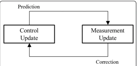
The Kalman filter has two update procedures as shown in Figure 2. One is a control update and the other is a measurement update. In the control update, we estimate the state with the previous state and an action parameter (vector). In the measurement update, the state is corrected by sensor information. The equa-tions of Kalman filter are presented in Table 2.
3. Proposed method
In this section, we explain the proposed hand detection and tracking algorithm. Figure 3 shows the steps of the proposed method. First, we get a depth image from the depth sensor, and create a motion image which is the accumulated difference images. Then, we reduce the noise with the spatial filter and the morphological
operation. Motion clustering method is proposed to find motion clusters. Then, initial hand detection is per-formed among the clusters with wave motion. Finally, the Kalman filter is used to track the hand.
3.1. Preprocessing
The depth image from the depth sensor has various sources of noise such as reflectance and mismatched patterns. Sometimes these noises are detected as real motion information. Therefore, noise reduction should be performed before hand detection. Also preproces-sing includes clustering algorithm for initial hand detection.
Figure 1Comparing color and depth images under different illumination conditions.(a)color image in normal illumination;(b)depth image in normal illumination;(c)color image in low illumination;(d)depth image in low illumination.
Table 1 Advantage and disadvantage of color and depth information
Color information Depth information
Advantage Easy to find feature Robust to light variation Non-intrusive method Getting real depth value Non-intrusive method Disadvantage Sensitive to light conditions Hard to find features
Occlusion Noise in edges
Occlusion Figure 2The procedures of Kalman filter. Parket al.EURASIP Journal on Advances in Signal Processing2012,2012:36
http://asp.eurasipjournals.com/content/2012/1/36
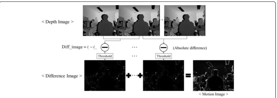
3.1.1. Motion image (accumulated difference image) We use the motion image which is the accumulated dif-ference image. The process of generating the motion image is shown in Figure 4. First, we store five consecu-tive images in the chronological order. Then, we obtain the difference image which is the previous frame (it-1)
subtracted from the current frame (it), as shown in (1).
Diff imaget=it−it−1 (1) We accumulate difference images. In this accumulated image, all movement of human, object, and noise are represented. Next, noise reduction, motion clustering, and hand detection procedures are applied to this motion image.
3.1.2. Noise reduction
We use a spatial filtering and a morphological proces-sing for noise reduction. When the noise reduction
method is applied to the motion image, real motion can be shown clearly. A 5 × 5 aperture median filter is used for spatial filtering. The median filter replaces the pixel value with the median value of the sub-image with aper-ture [23]. This median filter provides excellent salt and pepper noise reduction with considerably less blurring. As the noise pattern of the motion image is very similar to salt and pepper noise, the median filter is very effec-tive. We also use morphological processing for noise reduction. We use the opening operation which consists of erosion followed by dilation [23]. The basic effect of the opening operation is to reduce the outer shape of the object by erosion and to expand the outers. Gener-ally, this operation smooths the outers, splits the narrow region, and removes the thin perimeter. Thus, the open-ing operation removes the randomly generated noise and smooths the original image. The erosion operation slips off the object or particles layer, reducing irrelevant pixels and small particles from the image. The dilation operation does the inverse of the erosion operation. It attaches layers to the object or particles, and it can return the eroded objects or particles to their original size. These operations are highly effective for the depth image noise reduction.
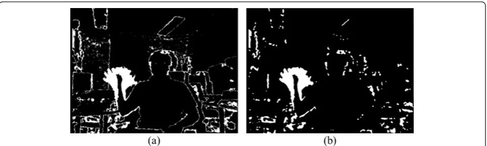
Figure 5a shows the original motion image and Figure 5b shows the result of the noise removal methods of the spatial filtering and the morphological processing on our experimental motion image.
3.1.3. Motion clustering
In this section, we describe how to cluster motion regions from the motion image. First we select con-nected components from the motion image. Then the obtained connected components are clustered. These clusters are possible candidates for the hand. The selected clusters can be either real motion or noise. The noise clusters are usually small or split fre-quently, so if the size is smaller than some threshold, then we can decide it as a noise cluster, and remove it.
To decide the threshold of the size, we use polynomial regression method. First, we obtain the size of a hand from each distance of 60-750 cm with every 10-cm interval. With the obtained hand size data, we employ the polynomial regression method to fit a curve to the
Table 2 Summary of Kalman filter
Kalman filter Control Measurement
Update xt=Atxt−1+Btut+εt zt=Ctxt+δt
Mean μ¯t=Atμt−1+Btut μt =μ¯t+Kt(zt−Ctμ¯t)
Covariance ¯t=Att−1ATt +Rt t= (I−KtCt)¯t
Kalman gain - Kt=¯tCTt(Ct¯tCTt +Qt)−1
dataset [24]. We use the fifth-order polynomial model given by (2)
g (α,x) =αTp(x), (2)
where
α= [α1α2α3α4α5α6]T (3)
and
p(x) = [ 1x x2x3x4x5]T, (4)
Because the fifth-order polynomial model is enough to model the obtained data. Givenmdata points, we use the least-squares error minimization objective given by (5)
s(α,x) = m
i=1
[yi−g (α,xi)]2= [y−pα]T[y−pα] (5)
where y = [y1,...,ym]T is the known data which we
obtained in the hand size experiment.p represents the
Jacobian matrix ofp(x):
P= ⎡ ⎢ ⎢ ⎢ ⎣
1x1 x12 x13 x14 x15 1x2 x22 x23 x24 x25
..
. ... ... ... ... ... 1xmxm2xm3xm4xm5
⎤ ⎥ ⎥ ⎥
⎦ (6)
Finally, we can estimate the parameter vectora from
Equation (7), and the result is given in Equation (8).
α= (pTp)−1pTy (7)
α= ⎡ ⎢ ⎢ ⎢ ⎢ ⎢ ⎢ ⎣ 327.982426870878 - 3.28281895300308 0.0152427222491653 - 3.54409649514619e - 05 3.98934813043004e - 08 - 1.73104221405172e - 11
⎤ ⎥ ⎥ ⎥ ⎥ ⎥ ⎥ ⎦ (8)
Then, we can find the fitted curve to the hand size dataset at any distance with Equation (9).
ˆ
y=αT·p (9)
whereyˆ denotes the estimated number of pixels at
dis-tance p. Figure 6 shows the result of the fitted curve
from 60 to 750 cm. In figure, the ‘x’ represents real
hand-size data and the ‘o’ denotes the hand size esti-mated by the polynomial regression function.
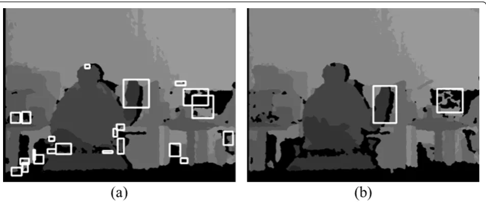
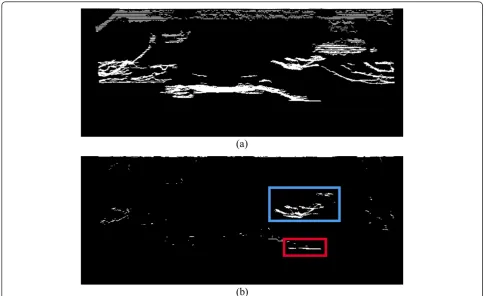
Now, we can choose the threshold by this regression function. Figure 7a shows the result of motion cluster-ing. The noise clusters still remain. Figure 7b shows the result of motion clustering with the threshold by the hand size. In the hand detection process, we find the hand cluster among those clusters.
We reduce the number of clusters by the polynomial regression method. Then, if other motions are over-lapped behind a hand, the hand cannot be found, because the near region of the hand in the motion image turns into white. This situation is shown in Fig-ure 8.
In order to find a hand cluster in this situation, we use the concept of bird’s eye view image. The bird’s eye view is an elevated view of a scene from above. This
bird’s eye view can be easily generated with 3D depth
information. The depth image and the motion image are depicted on theX-Yplane. In the overlapped situation,
however, we need to analyze X-Z plane information.
The X-Z plane of the scene can be the bird’s eye view as shown in Figure 9a. This figure is the X-Z plane of the original depth image. Then we consider this with the motion image above Figure 8b. We extract motion information from the original bird’s eye view and gener-ate Figure 9b. We call this figure as the motion bird’s eye view. The white regions of Figure 9b represent the motion, which has the same meaning as the white
Figure 4The process of generating the motion image.
Parket al.EURASIP Journal on Advances in Signal Processing2012,2012:36 http://asp.eurasipjournals.com/content/2012/1/36
regions of motion image. In Figure 9b, the small rectan-gle represents the front part which is the hand and the big rectangle represents the rear part which is the mov-ing body. Therefore, we can separate the hand part from the moving body like Figure 8a.
3.2. Initial hand detection
In the preprocessing section, we generated the motion image by accumulating difference images, reduced the
noise in the motion image, and found the motion clus-ters. In this section, we find the hand cluster from the remaining clusters in the image shown in Figure 7b.
To find the hand, we set the condition of hand wave motion, which consists of a side-to-side motion sequence. First, we detect the direction of cluster move-ments using a motion template [25,26]. The motion tem-plate is an effective method for tracking general movement, and it is especially useful for gesture
Figure 5The original motion image and reduced noise motion image.(a)The original motion image;(b)reduced noise motion image.
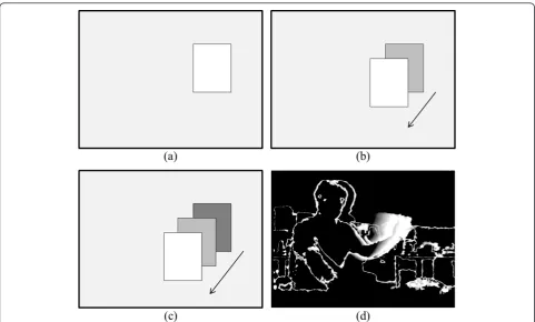
recognition. A cluster is needed for using the motion template. We already obtain the clusters from the motion image. Thereafter, we assume that we have a well-seg-mented cluster which is the white rectangle shown in Figure 10a. This image is referred to as the motion his-tory image. The white region of this image represents that all of the pixels in this region are set to the floating point. As the rectangle moves, a new cluster is calculated from the new current motion image and stacked to the motion history image. In Figure 10b, c, the white rectan-gle represents the new cluster and the previous cluster of old motions have become darker. The darkest rectangle denotes the oldest motion. And the rectangle is becom-ing lighter in consecutive order. These sequentially fadbecom-ing
rectangles represent the movement of clusters. Figure 10d shows the motion history image in depth space.
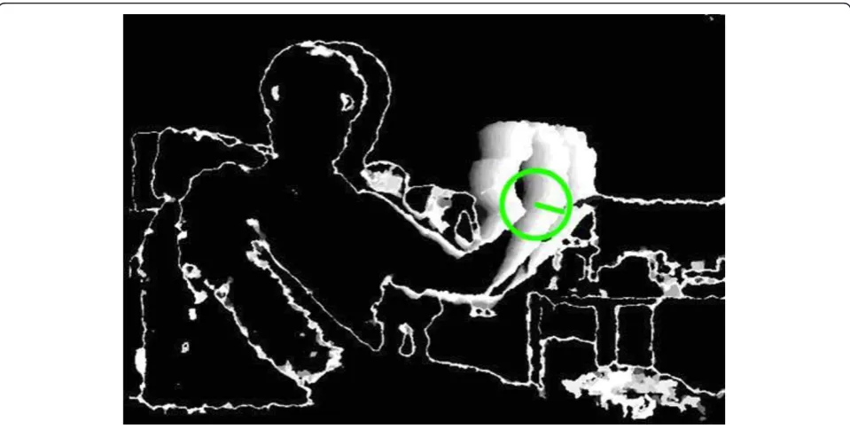
From the motion history image, we can derive the direction by taking the gradient. The gradient can be calculated by the Sobel gradient function and the Scharr gradient. Some of gradients calculated from the motion history image are invalid. Those occur when non-move-ment regions have zero gradients and outer edges of the cluster have large gradients. Since we know the time between frames, we can calculate the range of gradients, and we can remove the invalid gradients. Finally, we can decide the global gradient as the direction. Figure 11 shows the direction of clusters. The line in the circle shows the direction that the clusters are moving toward.
Figure 7Motion clustering with hand size.(a)Before applying the threshold of hand size;(b)after applying the threshold of hand size.
Figure 8The overlapped situation in depth image and motion image.(a)Depth image of overlapped situation;(b)motion image of overlapped situation.
Parket al.EURASIP Journal on Advances in Signal Processing2012,2012:36 http://asp.eurasipjournals.com/content/2012/1/36
Next, we find the hand cluster using wave motion detection. From the movement clusters in Figure 7b, we can calculate their directions. Figure 12 shows the direc-tion of clusters in the modirec-tion image.
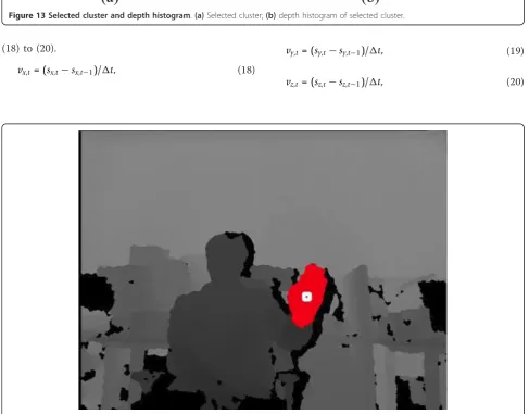
The method that we use for detection of wave motion is counting the number of direction changes of the cluster. We set the condition of wave number to three times, and count the number of times that clusters move left to right. We also assume that the hand is in the closest position to the camera. With this assumption the hand is the part of the detected hand cluster with the smallest depth value. We use the depth histogram to find the hand in the selected cluster. Figure 13a shows the selected cluster, and Figure 13b shows the depth histogram of the cluster. In the depth histogram, we remove the pixels under 600 mm because PrimeSensor cannot measure the depth less than 600 mm. Therefore, we initialize the hand in the first peak of the depth histogram over 600 mm which is near 1000 mm.
Figure 14 shows the result of the initial hand detection. This detection method is robust to illumination conditions. But the edge noise and reflection noise can be regarded as motion clusters. Sometimes these noise clusters may satisfy the size condition and the wave motion, and this may fal-sely detected as the hand. We use a tracking method to eliminate possible false detection situation.
3.3. Hand tracking
In [15,27,28], many object tracking methods are explained. Among these, the Kalman filter has the fol-lowing advantages for hand tracking. The first is compu-tational efficiency; the Kalman filter needs small data storage for previous data in operating the recursive pro-cess, because we only need information of the previous state, and not the whole previous frame. The second advantage is that the Kalman filter is suitable for treat-ing a time varytreat-ing signal. Therefore, we apply the Kal-man filter for hand tracking.
The Kalman filter is used for object tracking in many applications. Usually they use the state which is two dimensions for visual images. But as we need to add depth information, the state is designed as three dimen-sions. We assign depth information asz-axis values. So we make the state with three dimensions in (10).
S= ⎡ ⎣ssxy
sz ⎤
⎦ (10)
sx andsyrepresent the pixel position of the image,sz
represents the pixel value which is the depth value at position (sx,sy) in the depth image. This 3D state can more accurately estimate the hand position. For the
control vector, we use 3D vectors as the velocity of each axis in (11).
u= ⎡ ⎣vvxy
vz ⎤
⎦ (11)
For the measurementz, we use the same dimension of
stateSin (12).
z= ⎡ ⎣mmxy
mz ⎤
⎦ (12)
These vectors are the initial setting for the Kalman filter.
The Kalman filter needs hand detection in every frame for tracking. We use the following hand detection method during tracking. First, we define the reference point in the hand. This point is obtained as the central point of an ellipse which fits to the detected hand in the initial hand detection process. The central point is the cross point of the major axis and the minor axis of the fitted ellipse. We use this reference point in tracking. The method of detection is that store the current refer-ence point and cluster, and then find all the motion clusters in the next frame. Comparing with the previous
selected cluster, we can choose the current selected clusters with Equation (13) and Equation (14).
Current.x¡ Previous.x+ Previous.width/2,
Previous.x+ Previous.width/2<Current.x+ Current.width. (13)
Current.y¡ Previous.y+ Previous.height/2,
Previous.y+ Previous.height/2<Current.y+ Current.height. (14)
The nominated motion clusters should be fitted to the hand size which is found from the polynomial regres-sion method. This nominated point is now the current hand cluster, and we store the reference point.
Applications of Kalman filter for tracking usually fix the control update as constant. In our algorithm, the velocity of the hand continuously changes. We update the velocity of each axis for every frame. Therefore, the position of the tracked hand is more accurate. We apply the following equations to predict the stateS.
sx,t =sx,t−1+vx,t−1t, (15)
sy,t=sy,t−1+vy,t−1t, (16)
sz,t=sz,t−1+vz,t−1t, (17)
Figure 10Motion history image and Motion template procedure. Motion history image at time(a)t;(b)t +1;(c)t+ 2;(d)Depth motion history image.
Parket al.EURASIP Journal on Advances in Signal Processing2012,2012:36 http://asp.eurasipjournals.com/content/2012/1/36
We assume that the movement of the human hand is linear. sx, t, sy, tandsz, tare the pixel and depth
infor-mation at time t position. Δt is the interval time
between the previous and the current frames. Equa-tions (15) to (17) predict the position and the depth value from the hand position and the depth value of
the previous position and control vector which is updated in the previous process. The sz, t has the limit,
because the human hand moves within a limited reach range; we use not onlyX- andY-axis limits, but also a
Z-axis limit. We apply the following equations for
updating elements of the control vector, (vx,vy,vz) with
(18) to (20).
vx,t= (sx,t−sx,t−1)/t, (18)
vy,t= (sy,t−sy,t−1)/t, (19)
vz,t= (sz,t−sz,t−1)/t, (20)
Figure 13Selected cluster and depth histogram.(a)Selected cluster;(b)depth histogram of selected cluster.
Figure 14Result of the initial hand detection.
Parket al.EURASIP Journal on Advances in Signal Processing2012,2012:36 http://asp.eurasipjournals.com/content/2012/1/36
Figure 15Hand tracking using Kalman filter.
Using the depth axis in Kalman filter tracking, we can track the hand more accurately and robustly. Figure 15 shows the result of hand tracking with depth informa-tion. The white point represents the current hand posi-tion and the gray points indicate the previous hand positions.
4. Experimental results
The experimental environment is a PC with Intel®
Core™ i5 CPU 750 @ 2.67 GHz 2.66 GHz, and to
obtain depth information we used Primesense’s
Pri-meSensor development kit. The sensor obtained the depth image as follows. The IR light of PrimeSensor scatters the IR pattern, and the depth camera gets the pattern and creates the depth image. It also supports the color image. The resolution of the depth image is VGA (640 × 480), and the maximum frame rate is 60 fps. The resolution of the color image is UXGA (1600 × 1200). The operating range is 0.6-3.5 m [23]. In the proposed method, we use only the depth image.
4.1. Hand detection experiment
We perform hand detection experiment using the pro-posed initial hand detection method. We use the initial hand motion condition for finding the initial hand posi-tion. The wave motion is used as the initial hand moposi-tion. The experiment is performed 100 times and, we set three times of hand waving as the detecting condition. When the number of wave motion is 3, we assume hand detec-tion is performed. Figure 16 shows the result of the hand detection experiment. The result says that the count of three times satisfying the above condition is 91%. And we can detect initial hand 100% at most five times waving motion of hand. In the experiment, the waving motion is continued until the system detects the hand.
4.2. Depth-based hand tracking experiment
The first hand tracking experiment is findingX- andY-axis errors of the hand tracking at three distances. We manually gave the central hand position for the ground truth and compared it with the result of the proposed hand tracking.
Figure 17Result of the hand tracking experiment. Hand tracking(a)at 1 m distance;(b)at 2 m distance; and(c)at 3 m distance. Parket al.EURASIP Journal on Advances in Signal Processing2012,2012:36
http://asp.eurasipjournals.com/content/2012/1/36
The movement of hand is the square and triangle shapes, as shown in Figure 17. In Figure 18, we show
the measured distance error at each axis,X andY. The
dashed line represents the ground truth which is
manually detected and the solid line represents the results of tracking using the Kalman filter. The results show that when tracking in the long distance smaller tracking error is observed compared to when tracking in the short distance.
The 2D errors of the hand tracking experiment are shown in Table 3 where the error unit is denoted by pixel. The largest error occurred in the 1-m experiment, and the smallest error in the 3-m tracking experiment.
Table 3 The result of tracking error in 2D
1 m 2 m 3 m
Error (Pixel) 18.5623 7.6045 3.6696
Because the hand motion should be smaller at the longer distance on each axis, the 3-m tracking result is more accurate than the 1-m tracking result.
The second hand tracking experiment is finding the error of the hand tracking inZ-axis. For this experiment, we use two types of motions, the one is a push motion and the other is a spring motion which draws a circle in a push motion. For the push motion, we push two times in one experiment. For the spring motion, we draw three cir-cles. We obtained the data sets of each experiment from 12 persons with 10 times for each person.
Figure 19 a shows the result of 3D view of the push motion and Figure 19b shows the result of 3D view of the spring motion. Table 4 shows the average mean square error of each axis for 120 trials. The unit of X-and Y-axis error is pixel and unit of Z-axis is a
milli-meter. The error ofZ-axis is refined by Kalman filter
and hence the error is low in 13-30 mm.
4.3. Depth-based hand tracking and color-based hand tracking
We compare the performance of depth-based and color-based hand trackings. We used the Camshift [29] for the color-based hand tracking. After the initial hand detection, the hand is tracked by the proposed method with depth information, and independently by the Camshift with color information. For the Camshift tracker, the 5 × 5 window center is set to the initial hand point in order to extract the color histogram.
The ground truth is measured by color information with a marker which is attached to the hand. The depth and color information are calibrated. Therefore, we used the point of the ground truth for each track-ing method.
The gestures of hand used for the experiment are the alphabet shapes such as ‘a’, ‘b’, ‘c’, and basic shapes ‘square’, ‘triangle’, and‘circle’. Each experiment is per-formed at distances of 1, 2, and 3 m. The datasets of each experiment are obtained from 10 persons with 10 times for each person. Figure 20 shows the result of each gesture at 3 m. The solid line of each figure is the result of the proposed depth-based hand tracking method, the dotted line represents the result of Cam-shift tracking method and the dashed line means the ground truth of hand.
The depth-based hand tracking method usually tracked the shapes well. The color-based method with Camshift fails when the hand overlapped an object or a face of similar hue intensity. Table 5 shows the average
pixel error of the proposed depth-based tracking onX
and Y-axis for 100 trials. Table 6 shows the average
error of the color-based tracking on X and Y-axis for
100 trials. The distance of the ground truth for each tracking method is calculated in pixel units since Cam-shift cannot obtain depth information. The depth-based hand tracking is demonstrated to show the better per-formance than the color-based Camshift in the same bright light conditions. Under dark light conditions, the proposed method can track the hand well but the Cam-shift cannot extract the hue sample from the color image. Figure 21 shows the 3D plot of the proposed depth-based hand tracking result. Several points of results are sparked, but the Kalman filter refined those errors.
Figure 19Result of the hand tracking experiment in 3D. 3D view of(a)push motion;(b)spring motion.
Table 4 The result of tracking error in 3D
X-axis (pixel) Y-axis (pixel) Z-axis (mm)
Push motion 3.8867 6.4345 30.812 Spring motion 5.3170 5.0516 13.628
Parket al.EURASIP Journal on Advances in Signal Processing2012,2012:36 http://asp.eurasipjournals.com/content/2012/1/36
5. Conclusion
We proposed a novel hand detection and a tracking method using depth information. We make the motion image, as a basic source of the proposed hand tracking system, which is the accumulated difference image from depth image sequences. In the preprocessing stage, we perform noise reduction, applying a spatial filtering and
a morphological processing, and motion clustering, obtaining the moving region from the motion image. We detect the hand from this motion clusters using waving motion. We also suggest three-axis Kalman filter for tracking. Comparing the proposed method with
Figure 20Result of the depth-based and color-based hand tracking. Result of gesture(a)’a’tracking;(b)’b’tracking;(c)’c’tracking;(d)
’square’tracking;(e)’triangle’tracking; and(f)’circle’tracking.
Table 5 The mean pixel error of depth-based hand tracking
Gestures
a b c Square Triangle Circle
Distance (pixel) 1 m 8.506 7.557 6.369 7.798 6.831 6.421 2 m 5.837 6.544 5.053 5.218 5.119 6.223 3 m 4.822 6.398 4.122 3.885 3.776 4.263
Table 6 The mean pixel error of color-based hand tracking
Gestures
a b C Square Triangle Circle
Distance (pixel)
1 m
51.571 11.921 10.059 33.482 69.155 63.262
2 m
11.393 55.969 20.909 39.999 27.950 90.738
3 m
color-based method, we can see the effectiveness of the proposed method. Especially, the depth information-based method is very robust to the light variation envir-onment. As for the future work, in order to improve the accuracy of tracking, more effective noise reduction methods or other tracking methods such as Unscented Kalman filter or particle filter can be considered.
Acknowledgements
This work was supported by the National Research Foundation of Korea (NRF) grant funded by the Korea government (MEST) (No. 2011-0016302). And this research was supported by Basic Science Research Program through the National Research Foundation of Korea (NRF) funded by the Ministry of Education, Science and Technology (2010-0011472).
Author details
1
Department of Electrical and Electronic Engineering, Yonsei University, 134 Shinchon-Dong, Seodaemun-Gu, Seoul, Korea2Future IT Convergence Lab,
LG Electronics Advanced Research Institute, 221, Yangjae-Dong, Seocho-Gu, Seoul, Korea
Competing interests
The authors declare that they have no competing interests.
Received: 1 June 2011 Accepted: 17 February 2012 Published: 17 February 2012
References
1. VI Pavlovic, R Sharma, TS Huang, Visual interpretation of hand gestures for human-computer interaction: a review. IEEE Trans Pattern Anal Mach Intell. 19(7), 677–695 (1997). doi:10.1109/34.598226
2. A Just, S Marcel, A comparative study of two state-of-the-art sequence processing techniques for hand gesture recognition. Comput Vis Image Understand.113(4), 532–543 (2009). doi:10.1016/j.cviu.2008.12.001 3. B Ionescu, D Coquin, P Lambert, V Buzuloiu, Dynamic hand gesture
recognition using the skeleton of the hand. EURASIP J Appl Signal Process. 2005, 2101–2109 (2005). doi:10.1155/ASP.2005.2101
4. DJ Sturman, D Zelter, A survey of glove-based input. IEEE Comput Graph Appl.14(1), 30–39 (1994)
Figure 213D view of depth-based hand tracking result. 3D view of gesture(a)’a’;(b)gesture‘b’;(c)gesture‘c’;(d)gesture‘square’;(e) gesture‘triangle’;(f)gesture‘circle’.
Parket al.EURASIP Journal on Advances in Signal Processing2012,2012:36 http://asp.eurasipjournals.com/content/2012/1/36
5. RY Wang, J Popovic, Real-time hand-tracking with a color glove. ACM Trans Graph.28(3), 1–8 (2009)
6. C Shan, T Tan, Y Wie, Real-time hand tracking using a mean shift embedded particle filter. Pattern Recogn.40(7), 1958–1970 (2007). doi:10.1016/j.patcog.2006.12.012
7. Z Li, R Jarvis, Real time hand gesture recognition using a range camera, in Proceedings of Australasian Conference on Robotics and Automation (ACRA), Sydney, Australia, (December 2009)
8. R Kjeldsen, J Kender, Toward the use of gesture in traditional user interfaces, inProceedings of the Second International Conference on Automatic Face and Gesture Recognition, Killington, VT, USA, pp. 151–156 (October 1996)
9. K Imagawa, S Lu, S Igi, Color-based hands tracking system for sign language recognition, inIEEE International Conference on Automatic Face and Gesture Recognition, Nara, Japan, pp. 462–467 (April 1998)
10. B Stenger, A Thayananthan, PHS Torr, R Cipolla, Model-based hand tracking using a hierarchical bayesian filter. IEEE Trans Pattern Anal Mach Intell.28(9), 1372–1384 (2006)
11. PrimeSensor http://www.primesense.com
12. P Breuer, C Eckes, S Muller, Hand gesture recognition with a novel IR time-of-flight range camera–a pilot study. Lecture Note Comput Sci.4418, 247 (2007). doi:10.1007/978-3-540-71457-6_23
13. D Grest, V Kruger, R Koch, Single view motion tracking by depth and silhouette information, inProceedings of the Scandinavian Conference on Image Analysis, Aalborg, Denmark, pp. 719–729 (June 2007)
14. C Manresa, J Varona, R Mas, F Perales, Hand tracking and gesture recognition for human-computer interaction. Electron Lett Comput Vis Image Anal.5(3), 96–104 (2005)
15. A Yilmaz, O Javed, M Shah, Object tracking: a survey. ACM Comput Surv. 38(4), 1–45 (2006)
16. TB Moeslund, A Hilton, V Kruger, A survey of advances in vision-based human motion capture and analysis. Comput Vis Image Understand.104 (2-3), 90–126 (2006). doi:10.1016/j.cviu.2006.08.002
17. H Lu, KN Plataniotis, AN Venetsanopoulos, A full-body layered deformable model for automatic model-based gait recognition. EURASIP J Adv Signal Process.2008, 13 (2008)
18. I Oikonomidis, N Kyriazis, AA Argyros, Efficient model-based 3D tracking of hand articulations using Kinect, inBritish Machine Vision Conference, Dundee, UK, pp. 101.1–101.11 (August 2011)
19. M Bray, E Koller-Meier, P Muller, LV Gool, NN Schraudolph, 3D hand tracking by rapid stochastic Gradient Descent using a skinning model, in1st European Conference on Visual Media Production, London, UK, pp. 59–68 (March 2004)
20. MB Holte, TB Moeslund, P Fihl, Fusion of range and intensity information for view invariant gesture recognition, inIEEE Computer Society Conference on Computer Vision & Pattern Recognition Workshops, Anchorage, AK, USA, pp. 1–7 (June 2008)
21. RE Kalman, A new approach to linear filtering and prediction problems. Trans ASME J Basic Eng.82, 34–45 (1960)
22. G Bishop, G Welch, An introduction to the Kalman filter, inSIGGRAPH 2001, Course 8, Los Angeles, CA, USA (August 2001)
23. RC Gonzalez, RE Woods,Digital Image Processing, 3rd edn. (Prentice Hall, Upper Saddle River, NJ, 2008)
24. KA Toh, QL Tran, D Srinivasan, Benchmarking a reduced multivariate polynomial pattern classifier. IEEE Trans Pattern Anal Mach Intell.26(6), 740–755 (2004). doi:10.1109/TPAMI.2004.3
25. GR Bradski, JW Davis, Motion segmentation and pose recognition with motion history gradients. Mach Vis Appl.13(3), 174–184 (2002). doi:10.1007/ s001380100064
26. R Munoz-Salinas, R Medina-Carnicer, F Madrid-Cuevas, A Carmona-Poyato, Depth silhouettes for gesture recognition. Pattern Recogn Lett.29(3), 319–329 (2008). doi:10.1016/j.patrec.2007.10.011
27. FL Lewis,Optimal Estimation: With An Introduction to Stochastic Control Theory(Wiley, NY, 1986)
28. RG Brown, PYC Hwang,Introduction to Random Signals and Applied Kalman Filtering(Wiley, NY, 1997)
29. GR Bradski, Computer vision face tracking for use in a perceptual user interface, inIEEE workshop on Applications of Computer Vision, (Princeton, NJ, USA, 1998), pp. 214–219
doi:10.1186/1687-6180-2012-36
Cite this article as:Parket al.:3D hand tracking using Kalman filter in depth space.EURASIP Journal on Advances in Signal Processing2012 2012:36.
Submit your manuscript to a
journal and benefi t from:
7Convenient online submission 7Rigorous peer review
7Immediate publication on acceptance 7Open access: articles freely available online 7High visibility within the fi eld
7Retaining the copyright to your article