Wireless data transmission for high energy physics applications
Sebastian Dittmeier1,a, Richard Brenner2, Dragos Dancila2, Cedric Dehos3, Patrick De Lurgio4, Zelimir Djurcic4, Gary Drake4, Jose Luis Gonzalez Gimenez3, Leif Gustafsson2, Do-Won Kim5, Elizabeth Locci6, Ullrich Pfeiffer7, Dieter Röhrich8, Anders Rydberg2, André Schöning1, Alexandre Siligaris3, Hans Kristian Soltveit1, Kjetil Ullaland8, Pierre Vincent3, Pedro Rodriguez Vazquez7, Dirk Wiedner1, and ShimingYang7
1Physics Institute, Heidelberg University, Germany
2Department of Physics and Astronomy, Uppsala University, Sweden
3CEA/LETI/DRT/DACLE/LAIR, Grenoble, France
4Argonne National Laboratory, Argonne, IL 60439, USA
5Gangneung National University, Korea
6CEA/DRF/IRFU/SPP, Gif-sur-Yvette, France
7Institute for High-Frequency and Communication Technology, University of Wuppertal, Germany
8Department of Physics and Technology, University of Bergen, Norway
Abstract. Silicon tracking detectors operated at high luminosity collider experiments pose a challenge for current and future readout systems regarding bandwidth, radiation, space and power constraints. With the latest developments in wireless communications, wireless readout systems might be an attractive alternative to commonly used wired opti-cal and copper based readout architectures.
The WADAPT group (Wireless Allowing Data and Power Transmission) has been formed to study the feasibility of wireless data transmission for future tracking detectors. These proceedings cover current developments focused on communication in the 60 GHz band. This frequency band offers a high bandwidth, a small form factor and an already mature technology. Motivation for wireless data transmission for high energy physics application and the developments towards a demonstrator prototype are summarized. Feasibility studies concerning the construction and operation of a wireless transceiver system have been performed. Data transmission tests with a transceiver prototype operating at even higher frequencies in the 240 GHz band are described. Data transmission at rates up to 10 Gb/s have been obtained successfully using binary phase shift keying.
1 Introduction
High Energy Physics (HEP) experiments, as they are conducted at the LHC1, the HL-LHC2or at po-tential future colliders, are operated at ever increasing luminosities and event rates. Correspondingly, more and more data are generated by these experiments that have to be read out and processed. Es-pecially highly granular silicon detectors as they are used for vertexing and tracking pose a challenge for readout systems.
Today, readout systems typically use wired optical data transmission for data rates beyond 1 Gb/s per channel. However, radiation hardness issues, space and power constraints limit the usage of optical components in very dense pixel detector environments to places far outside the active volume. This is the case, for instance, for the vertex detector for the Phase-II upgrade of the ATLAS Inner Tracker (ITk) [1]. In these cases, wired copper transmission lines are used to transfer the data over several metres towards the optical drivers. Aiming for very high data rates, copper based transmission lines typically suffer from an increased impedance which limits the transmission of data rates of a few Gb/s to distances of a few metres. Developments in both wired optical and copper technologies are on-going, but a third, alternative technology relying on wireless data transmission might be attractive for future high rate readout systems in dense and hostile environments, as first described in [2]. Regarding bandwidth, wireless technologies have caught up and can deliver rates in the range of several gigabits per second, as well.
Wireless data transmission could help to reduce the number of cables, optical or copper, used for data transmission as well as their connectors, which are often prone to damage. With less cables and connectors, installation and repair of such a complex system like a tracking detector can be simplified. Moreover, cables contribute significantly to the material budget in the active detector volume, which leads to multiple scattering and acts as a source of secondary particles.
Wireless data transmission would further allow to realize completely different readout topolo-gies [2]. To keep a distinct level of modularity in a layer based silicon tracking detector, different layers can not be connected by wires within the active volume. Thus, directly in the active volume
1Large Hadron Collider
2High Luminosity-Large Hadron Collider
Layer 1 Layer 2 Layer 3 Outer enclosure
high pT track ~10cm
no communication between layers is possible and data has to be transferred to the outside, first. A wireless readout system would enable layers to communicate with each other. This could be used to enhance on-detector intelligence such as finding of tracks with high transverse momentum online as the data could follow the particle trajectories as depicted in figure 1. Fast track trigger applications might benefit from this readout topology [2].
Broadcasts of signals that are common in the detector could also be easily distributed using wire-less data transmission, as a signal emitted by a single transmitter can be received by several receivers at the same time. This could be interesting for detector synchronization or to distribute a system-wide reset or trigger signal.
These motivations have led to the formation of the WADAPT (Wireless Allowing Data and Power Transmission) consortium. The goal of this research group is to identify specific needs of projects that might benefit from wireless technologies with the objective of providing a common platform for research and development [3]. Along that line, a wireless data transmission demonstrator for HEP applications is developed and shortly described in section 3. Studies to demonstrate the feasibility of this technology for HEP are summarized in section 4. Section 5 shows some further prospects of wireless technologies operating at carrier frequencies above 200 GHz.
2 Wireless data transmission
Over the last years, wireless data transmission technologies have seen tremendous progress to handle the ever increasing demand on bandwidth. The latest developments in wireless standardization by IEEE foresee data rates beyond one gigabit per second [4], and this trend of increasing wireless data rate capabilities seems to continue even further [5].
The Shannon-Hartley theorem gives a limit on the maximum data rate of a transmission channel. It depends on two factors: the bandwidth, and the average signal to noise ratio over that bandwidth. For typical Wi-Fi at home, operating at carrier frequencies of 2.4 GHz or 5 GHz, the bandwidth avail-able per wireless channel is limited to a few tens of MHz. To achieve high data rates modulation schemes with high spectral efficiency3 have been developed. A reliable data transmission with high
spectral efficiency, however, requires complex signal processing and a high signal-to-noise ratio. Both typically come at the cost of a significant power consumption.
Improvements in silicon technologies over the last decades allow to produce ASICs operating at higher radio frequencies (RF). This also allows to allocate a larger bandwidth for a wireless channel. Especially the mm-wave band is of great interest to industry and appears also very attractive to the HEP community. In the 60 GHz band a total bandwidth of 9 GHz is available. This allows for high data rates even with simple modulation schemes like On-Off-Keying (OOK). Thus, RF devices can be produced without complex signal processing cicuitry and therefore low power consumption. The high frequencies furthermore allow for a high degree of miniaturization. For instance, antennas can be directly integrated in the chip. The free space path loss is significantly larger than at 2.4 GHz, thus the 60 GHz band is very well suited for safe, short distance communication.
Various examples of 60 GHz transceivers can be found in literature [6–9]. However, in order to qualify for HEP applications, a specific transceiver is required which fulfils the stringent constraints on power consumption and should be able to operate in extremely hostile radiation environments. For this application, a demonstrator prototype is currently under development.
Figure 2. The two antennas under test for the bond wire study [10]. The left antenna has a solid transmission line, while the transmission line of the right antenna is broken intentionally by a gap with a compensation circuit. In the lower right corner, a zoomed-in view of the gap bridged by a single bonding wire can be seen.
3 A 60 GHz demonstrator for HEP
The purpose of the demonstrator is to validate the feasibility of wireless data transmission for HEP applications. It has to fulfil several requirements: It must be operational after irradiation up to very high doses as expected for the HL-LHC. It has to provide data rates of the order of 5 Gb/s, similar to what is expected per link from the silicon detectors of the large experiments at HL-LHC. At the same time power efficiency is crucial. In order to benefit from wireless data transmission, the power consumption of the on-detector readout part should be reduced compared to commonly used readout architectures.
At Heidelberg University a wireless transceiver chip is under development [11, 12]. The prototype will be produced in the IBM SiGe BiCMOS 130 nm 8HP process. Utilizing the full 9 GHz bandwidth and On-Off-Keying (OOK) modulation, the target data rate of this device is 4.5 Gb/s. The targeted power consumption is about 150 mW for a data transmission over distances between 20 cm and 1 m. This corresponds to an energy efficiency of about 33 pJ/bit. The actual transmission distance that can be achieved for a given power consumption, however, is largely influenced by the choice of the external antenna.
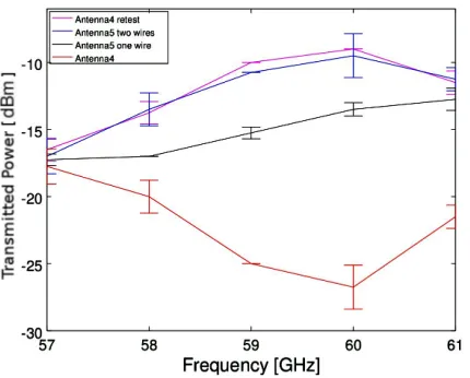
For the demonstrator, a printed circuit board will be designed with an on-board antenna. Directive patch antennas have been successfully fabricated and simulations of the reflection loss have been verified in measurements [13]. The connection between the RF output of the transceiver and the antenna on the demonstrator will potentially be realized using wire bonds. Therefore, a wire bonding study is performed using the patch antennas shown in figure 2. The impedance of a standard wire bond is found not to match the antenna under test properly, but signal losses can be compensated using an additional second wire and a compensation circuit, see figure 3 [10].
4 Studies in the 60 GHz band
Several studies have been conducted with the scope of testing the feasibility of wireless data trans-mission in the 60 GHz band for HEP applications. These include simple data transtrans-mission studies as well as interference and link density studies.
Figure 3.Measured intensity for different antenna configurations [10]. Purple curve: Antenna with solid trans-mission line (figure 2, left) serves as reference. Black curve: Antenna with gap included in the transtrans-mission line (figure 2, right image) and the gap is bridged by a single wire bond. Blue curve: The same antenna with gap, but with two wires to close the gap. The full signal is recovered by using two bond wires instead of one. The red curve belongs to the same antenna as the purple curve, but part of the signal was lost due to an issue with the etching process.
distance of 22 cm. An upper limit on the bit error rate was measured to be at the 10−14 level [14]. CEA-LETI demonstrated data transmission at a rate of 3.8 Gb/s using a transceiver produced in 65 nm CMOS technology [6].
A wireless detector readout scheme as illustrated in figure 1 relies on the simultaneous use of the same frequencies between different layers to fully exploit the available bandwidth. This is possible as typical silicon detector modules are metallized and thus fully reflective for waves in the 60 GHz band. This can be confirmed by a measurement of the transmission loss through an ATLAS SCT module, which is found to be at least 50 dB in the frequency range from 57.3 to 61.3 GHz, see figure 4 [14].
While enabling to re-use frequencies between different layers, the high reflectivity of the modules can potentially lead to cross talk between neighbouring links on the same layer. But the free space path loss in the 60 GHz band is already so large that only links that are very close can potentially interfere. In addition, the detector environment has one clear advantage compared to mobile applications: Once the system is installed, it is completely stationary. This allows to perform design studies and ray-tracing simulations with detailed detector models beforehand to reduce interferences and therefore optimize the overall bandwidth usage.
Position along module [mm]
30 40 50 60 70 80 90 100
Average transmission loss [dB]
60 −
58 −
56 −
54 −
52 −
50 −
48 −
Barrel module
Noise level
Figure 4. Transmission loss of mm-waves through an ATLAS SCT barrel module. The transmission loss is averaged over the frequency range from 57.3 to 61.3 GHz and measured over different positions along the module. The noise level indicates the minimum sensitivity of the spectrum analyser. The uncertainties represent the RMS of the averaged measurements. Plot taken from [14].
In order to further qualify the 60 GHz technology for HEP applications, it has to be ensured that the wireless links do not disturb the detector’s electronics. Tests with an ATLAS ITK hybrid with ABCn130 readout ASICs showed no observable effect on the module’s performance [14]. A similar measurement was conducted with an HV-MAPS prototype developed for Mu3e. No effect on this sensor’s performance due to the wireless link was observed, as well [14]. We therefore conclude that wireless links at 60 GHz are a safe readout option for state of the art silicon detectors.
5 Prospects of carrier frequencies above 200 GHz
Recent developments in silicon technologies allow for even higher carrier frequencies, which, in turn, allow to use an even larger bandwidth. Examples of wireless transceivers operating at 210 to 283 GHz can be found in [15–17].
We performed data transmission studies with a 240 GHz transmitter and receiver chipset [16]. The chipsets are glued and wire bonded to printed circuit boards. The chipsets feature an integrated ring antenna for signal transmission and reception. To increase the antenna’s directivity, silicon lenses with a gain of more than 25 dBi are mounted just below the circuits. A transmission distance of about 40 cm was realized. A photo of the setup in the laboratory is shown in figure 5. The intermediate frequency (IF) bandwidth was characterized at a fixed carrier frequency of 235 GHz using an inter-mediate frequency sweep in the range of 0 to 20 GHz and measuring the received signal in a spectrum analyser. The 3/6-dB IF bandwidth was measured to be 12/13 GHz, respectively, see figure 6.
Figure 5. Wireless link using the chipsets described in [16] at a transmission distance of about 40 cm in the laboratory.
Intermediate Frequency [GHz]
0 2 4 6 8 10 12 14 16 18 20
Power Loss [dB]
35 −
30 −
25 −
20 −
15 −
10 −
5 −
0 5
= 235 GHz
c
IF power: f
avg power: IF < 4 GHz
avg power - 3dB
Figure 6. The intermediate frequency spectrum measured with a spectrum analyser at the 240 GHz receiver. The intermediate frequency of the transmitter is varied between 0 to 20 GHz. The green line highlights the 3 dB bandwidth.
6 Summary and outlook
There has been huge progress in wireless data transmission technologies over the last couple of years. The mm-waves developments allow for extremely high data rates while also being very power effi -cient.
The advantages of a wireless readout system compared to wired ones as used in HEP today are manifold. The reduction of cables and connectors would help to reduce dead material inside detectors as well as ease the detector’s installation. New readout topologies for tracking detectors are possible which have great potential of enhancing fast track trigger capabilities.
A 60 GHz demonstrator is currently developed to show the potential of wireless data transmission for HEP applications. Studies to test the feasibility of wireless data transfer for tracking detectors have been conducted. High speed data transmission has been demonstrated with two setups at data rates of 1.76 Gb/s and 3.8 Gb/s. Carrier frequencies above 200 GHz allow for even higher data rates. A transmission at a data rate of 10 Gb/s has been demonstrated. For high density link environments in general, signal integrity can be ensured by exploiting directional antennas, polarization or attenu-ating reflections using an absorbing foam. In order to apply wireless data transfer in future detectors, detailed design studies will have to be conducted to demonstrate the full potential of wireless commu-nication and to create a working wireless readout system.
References
[1] M. Wensing (ATLAS), JINST12, C01093 (2017) [2] R. Brenner, S. Cheng, JINST5, C07002 (2010) [3] R. Brenner et al. (WADAPT) (2015),1511.05807
[4] IEEE Computer Society, doi:10.1109/IEEESTD.2012.6392842 (2012)
[5] ISSCC 2016 Trends (2016),http://isscc.org/doc/2016/ISSCC2016_TechTrends.pdf
[6] A. Siligaris et al., IEEE Journal of Solid-State Circuits (JSSC) (2011)
[7] C. W. Byeon, C. H. Yoon, C.S. Park, IEEE Trans. Microw. Theory Techn.61(2013) [8] A. Tomkins et al., Custom Integrated Circuits Conf. (CICC) (2008)
[9] C. Marcu et al., Proceedings of International Solid State Circuits Conference - ISSCC 2009 (2009)
[10] R. Brenner (2017),https://indico.cern.ch/event/608206/contributions/2451744 /attachments/1402081/2140369/Wifi_meeting20170127_wirebond.pdf
[11] H.K. Soltveit, R. Brenner, A. Schöning, D. Wiedner, JINST7, C12016 (2012)
[12] H.K. Soltveit, S. Dittmeier, A. Schöning, D. Wiedner, Nuclear Science Symposium and Medical Imaging Conference (NSS/MIC), 2013 IEEE pp. 1–6 (2013)
[13] D. Pelikan, N. Bingefors, R. Brenner, D. Dancila, L. Gustafsson, JINST9, C11008 (2014) [14] S. Dittmeier, A. Schöning, H.K. Soltveit, D. Wiedner, Nucl. Instrum. Meth.A830, 417 (2016),
1604.06259
[15] Z. Wang, P.Y. Chiang, P. Nazari, C.C. Wang, Z. Chen, P. Heydari, IEEE Journal of Solid-State Circuits49, 564 (2014)
[16] N. Sarmah, P.R. Vazquez, J. Grzyb, W. Foerster, B. Heinemann, U.R. Pfeiffer, 2016 11th Euro-pean Microwave Integrated Circuits Conference (EuMIC) (2016)
![Figure 2. The two antennas under test for the bond wire study [10]. The left antenna has a solid transmissionline, while the transmission line of the right antenna is broken intentionally by a gap with a compensation circuit.In the lower right corner, a zoomed-in view of the gap bridged by a single bonding wire can be seen.](https://thumb-us.123doks.com/thumbv2/123dok_us/8134328.1355716/4.482.101.383.82.205/antennas-transmissionline-transmission-intentionally-compensation-circuit-bridged-bonding.webp)

![Figure 5. Wireless link using the chipsets described in [16] at a transmission distance of about 40 cm in thelaboratory.](https://thumb-us.123doks.com/thumbv2/123dok_us/8134328.1355716/7.482.110.356.329.512/figure-wireless-using-chipsets-described-transmission-distance-thelaboratory.webp)
