1253 | P a g e
LOW-POWER SPLIT-RADIX FFT PROCESSORS
Avinash
1, Manjunath Managuli
2, Suresh Babu D
3ABSTRACT
To design a split radix fast Fourier transform is an ideal person for the implementing of a low-power FFT processor, because it has the lowest number of arithmetic operations among all the FFT algorithms. In the design of such processor, an efficient addressing scheme for FFT data as well as twiddle factors is required. The signal flow of SRFFT is the same as a redix-2 FF, and conventional address generation scheme of FFT data could also be applied to SRFFT however, SRFFT has irregular locations of twiddle factor and forbids the application of redix-2 address generation methods. This brief presents shared-memory low-power SRFFT processor architecture. We show that SRFFT can be computed by using a modified radix-2 butterfly unit. The
butterfly unit exploits the multiplier-gating technique to save dynamic power at the expense of using more
hardware resources. In addition, two novel address generation algorithms for both the trivial and nontrivial
twiddle factors are developed. Simulation results show that compared with the conventional radix-2
shared-memory implementations, the proposed design achieves over 15% lower power consumption when computing a
768-point complex-valued transform.
Keywords: -
Address generation, low power, radix-2,
split-radix fast Fourier transforms (SRFFT),
twiddle factors.
I. INTRODUCTION
The fast Fourier transform (FFT) is one of the most important and fundamental algorithms in the digital signal
processing area. Since the discovery of FFT, many variants of the FFT algorithm have been developed, such as
radix-2 and radix-4 FFT. In 1984, Duhamel and Hollmann [1] proposed a new variant of FFT algorithm called
split-radix FFT (SRFFT). Their algorithm requires the least number of multiplications and additions among all
the known FFT algorithms. Since arithmetic operations significantly contribute to overall system power
consumption, SRFFT is a good candidate for the implementation of a low-power FFT processor.
In general, all the FFT processors can be categorized into two main groups: pipelined processors or
shared-memory processors. Examples of pipelined FFT processors can be found in [2] and [3]. A pipelined architecture
provides high throughputs, but it requires more hardware resources at the same time. One or multiple pipelines
are often implemented, each consisting of butterfly units and control logic. In contrast, the
shared-memory-based architecture requires the least amount of hardware resources at the expense of slower throughput.
Examples of such processors can be found in [4] and [5]. In the radix-2 shared-memory architecture, the FFT
data are organized into two memory banks. At each clock cycle, two FFT data are provided by memory banks
and one butterfly unit is used to process the data. At the next clock cycle, the calculation results are written back
to the memory banks and replace the old data. The scope of this brief is limited to the shared-memory
1254 | P a g e
In the shared-memory architecture, an efficient addressing scheme for FFT data as well as coefficients (calledtwiddle factors) is required. For the fixed-radix FFT, previous works of this topic can be found in [5] and [6].
For split-radix FFT, it conventionally involves an L-shaped butterfly data path whose irregular shape has uneven
latencies and makes scheduling difficult. In this brief, we show that the SRFFT can be computed by using a
modified radix-2 butterfly structure. Our contribution consists of mapping the split-radix FFT algorithm to the
shared-memory architecture, leveraging lower multiplicative complexity of the algorithm to reduce the dynamic
power and developing two novel twiddle factor addressing schemes for the split-radix FFT.
The rest of this brief is organized as follows. Section II provides a theoretical comparison of the number of
complex multiplications between the radix-2 FFT and the SRFFT. Section III discusses the architecture of the
proposed design. Section IV provides the implementation results and Section V concludes this brief.
II. PROPOSED ALGORITHEM
A. Redix-2 Butterfly algorithmThe N-point DFT for a sequence x (n) is defined as
Where .
Radix-2 FFT algorithm reduces the order of computational complexity of Eq. 1 by decimating even and odd indices of input samples. There are two kinds of decimation in the time domain and decimation in frequency
(DIF) domain. Shows the flow graph for radix-2 DIF FFT for N = 16.
B. Redix-4 Butterfly algorithm
The N -point DFT of an input sequence is defined as
Given a complex data sequence
1255 | P a g e
with length N, the discrete Fourier transform (DFT) is defined asX(k) = N ∑−1 i=0
x(i)Wik N , for k = 0, 1, . . . , N − 1, (1)
where WN = exp(j2π/N), and j = √ −1. Throughout this paper, we define that a complex multiplication operation
requires four real multiplications and two real additions. Furthermore, it is noted that multiplying by {W0 4 ,
W1 4 , W2 4 , W3 4 } is treated as free of calculation, and multiplying by {W1 8 , W3 8 , W5 8 , W7 8 } only
requires two multiplications and two additions. In the following, we firstly introduce the modified radix-4 FFT
proposed by Bouguezel et al. [8], and then introduce the proposed algorithm derived from [8]. Assuming N
being the power of four, then (1) can be reformulated as
X(k) = N/ ∑ 4−1
l=0 ∑ 3 i=0 x(N/4 × i + l)W (N/4×i+l)k
N = N/ ∑ 4−1 l=0 Wlk N ∑ 3 i=0 x(N/4 × i + l)Wlk
Fig. 2: 4-point Radix-2 FFT
C. 8-point Radix-2 FFT:
An 8 input butterfly diagram has 12 2-input butterflies and thus 12*2 = 24 multiplies. N Log N = 8 Log (8) =
24. A straight DFT has N*N multiplies, or 8*8 = 64 multiplies. That's a pretty good savings for a small sample.
The savings are over 100 times
for N = 1024 and this increases as the number of samples increases. Fig.
1256 | P a g e
V. RESULT AND DISCUSSION
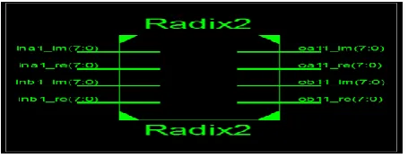
The RTL view of a radix-2 FFT contains „i_x0i , „i _x0r‟, „Ts0‟ , „Ts1‟ and output‟s „o_x0i‟, „o_x0r‟ which will
be connected to top-level modules. The top-level module feeds the data to FFT_radix-2 through above
mentioned inputs. The top-level schematic of radix-2 is shown in Fig.
Figure Top-level Schematic of radix-2
Internally radix-2 butterfly will add, multiply and subtract according to the structure of butterfly and gives the
output on „o_x0i‟, „o_x0r‟,. The internal RTL view is shown in Fig. explains logical slices mapping in FPGA. The written verilog code will be converted into FPGA related LUT‟s, MUX‟s, flip-flops looks like Fig. 10. The
mapping of slices would be different for different device selected.
Figure RTL view of Radix-2
Input sequence x(n) = {0,1,2,3,4,5,6,7}
1257 | P a g e
n = 0 1 2 3 4 5 6 7x = 0 1 2 3 4 5 6 7
y = 28.0000 -4.0000 + 9.6569i -4.0000 + 4.0000i -4.0000 + 1.6569i
-4.0000 -4.0000 - 1.6569i -4.0000 - 4.0000i -4.0000 - 9.6569i
>> fft
n = 0 1 2 3
4 5 6 7
1258 | P a g e
1.0000 + 1.0000i 2.0000 + 1.0000i 3.0000 + 1.0000i 4.0000 + 1.0000i
y = 20.0000 + 8.0000i
0
-4.0000 + 4.0000i 0
-4.0000
0
-4.0000 - 4.0000i 0
VI. CONCLUSIONS
In this brief, a shared-memory-based SRFFT processor is proposed. The proposed method reduces the dynamic
power consumption at the expense of more hardware resources. We also present two addressing schemes for
both the trivial and nontrivial twiddle factors. Since SRFFT has the minimum number of multiplications
compared with other types of FFT, the results could be more optimal in the sense of floating point operations.
REFERENCES
[1] P. Duhamel and H. Hollmann, “„Split radix‟ FFT algorithm,” Electron. Lett., vol. 20, no. 1, pp. 14–16, Jan.
1984.
[2] M. A. Richards, “On hardware implementation of the split-radix FFT,” IEEE Trans. Acoust., Speech Signal
Process., vol. 36, no. 10, pp. 1575–1581, Oct. 1988.
[3] J. Chen, J. Hu, S. Lee, and G. E. Sobelman, “Hardware efficient mixed radix-25/16/9 FFT for LTE systems,”
IEEE Trans. Very Large ScaleIntegr. (VLSI) Syst., vol. 23, no. 2, pp. 221–229, Feb. 2015.
[4] L. G. Johnson, “Conflict free memory addressing for dedicated FFT hardware,” IEEE Trans. Circuits Syst.
II, Analog Digit. Signal Process.,nvol. 39, no. 5, pp. 312–316, May 1992.
[5] D. Cohen, “Simplified control of FFT hardware,” IEEE Trans. Acoust., Speech, Signal Process., vol. 24, no.
6, pp. 577–579, Dec. 1976.
[6] X. Xiao, E. Oruklu, and J. Saniie, “An efficient FFT engine with reduced addressing logic,” IEEE
1259 | P a g e
[7] Z. Qian, N. Nasiri, O. Segal, and M. Margala, “FPGA implementation of low-power split-radix FFTprocessors,” in Proc. 24th Int. Conf. FieldProgram. Logic Appl., Munich, Germany, Sep. 2014, pp. 1–2.
[8] A. N. Skodras and A. G. Constantinides, “Efficient computation of the split-radix FFT,” IEE Proc. F-Radar
Signal Process., vol. 139, no. 1,
pp. 56–60, Feb. 1992.
[9] H. V. Sorensen, M. T. Heideman, and C. S. Burrus, “On computing the split-radix FFT,” IEEE Trans.
Acoust., Speech Signal Process., vol. 34, no. 1, pp. 152–156, Feb. 1986.
[10] J. Kwong and M. Goel, “A high performance split-radix FFT with constant geometry architecture,” in Proc.
Design, Autom. Test Eur. Conf.Exhibit. (DATE), Dresden, Germany, Mar. 2012, pp. 1537–1542.
[11] W.-C. Yeh and C.-W. Jen, “High-speed and low-power split-radixFFT,” IEEE Trans. Signal Process., vol.