DC-DC Converters for Fuel Cells
Shyamal Kumar Roy
Assistant Professor, Dept. of EE, Guru Nanak Institute of Technology, Kolkata, WB, India
ABSTRACT: This paper describes different types of DC-DC converters that are used for regulating the output voltage of fuel cell modules. A discussion of the operation of the fuel cells and the types of fuel cells is presented. The paper also describes regulation of the output voltage of the fuel cell using DC-DC converters.
KEYWORDS: Fuel cells, Flyback Converter, Full Bridge DC-DC Converter, Half Bridge Converter, Push Pull Converter.
I.INTRODUCTION
Fuel cells are environmentally friendly renewable energy sources, which can operate at efficiencies greater than most traditional energy production methods. Fuel cells are seen as ideal power source because of their low emission, low vibration, high efficiency, and high reliability. However, if hydrogen is produced through reformation process, carbon compounds can be emitted. Fuel cells are being used for both stationary and transportation applications. However, there are limitations associated with fuel cells. The output voltage of a fuel cell varies with load current and the age of the cell. The efficiency of the fuel cell is reduced with output ripple current. Fuel cell has slow response to load step response and has no overload capability. The other main limitation of the fuel cell is that it cannot accept any reverse current.
II.FUEL CELLS
A fuel cell is based on the principle that electricity can be produced by combining hydrogen and oxygen in a particular configuration. A fuel cell consists of cathode and an anode, and they are separated by a membrane. Hydrogen is applied to the anode of the fuel cell, where it is separated into electrons and positive hydrogen ions by a catalyst. The membrane separating the cathode and the anode permits the flow of the hydrogen ions and rejects flow of electrons. This rejection causes the electrons to take the circuit path to flow to the cathode. Once the electrons reach the cathode, they combine with oxygen and hydrogen ions to form water. The main property of a fuel cell is that, when pure hydrogen is used as the fuel, only water is produced as the byproduct. In order to achieve higher voltage rating, fuel cells are stacked in parallel. Based on the electrolyte used, fuel cells are classified into five different types: Alkaline Fuel Cells (AFCs), Phosphoric Acid Fuel Cells (PAFCs), Proton Exchange Membrane Fuel Cell (PEMFCs), Molten Carbonate Fuel Cells (MCFCs), and Solid Oxide Fuel Cells (SOFCs).
TABLE1. THE CATEGORIZATION OF FUEL CELLS
Type Electrolyte Operating Temperature,
0
C
Fuel Applications
AFC KOH 50-200 Pure H2 Transportation,
portable power PAFC Phosphoric acid ~ 220 Pure H2 stationary power
PEMFC Solid polymer 50-100 Pure H2 Transportation,
portable power, stationary power MCFC Lithium and
potassium carbonate
~650 H2, CO, CH4
and other hydrocarbons
Stationary power
SOFC Solid oxide electrolyte
500-1000 H2, CO, CH4
and other hydrocarbons
portable power, stationary power
III.ELECTRICAL CHARACTERISTICS OF FUEL CELL
The operation of a fuel cell is similar to that of a battery. However, fuel cell can produce unlimited amount of power as long as the fuel is supplied with sufficient energy density. The fuel cell’s output voltage varies with the load current and the age of the cell. The major factors which contribute to the fuel cell voltage drop are activation loss, concentration loss, and ohmic loss. Activation loss is due to the slowness of the reactions taking place inside the cell. Concentration loss is due to gas concentration changes at the surface of the electrode and ohmic losses are due to the resistance of the polymer membrane to the transfer of protons and the resistance of the electrode and the collector plates to the transfer of electrons. Fuel cells also exhibit a fast dynamic behaviour known as “charge double layer effect”. The above-mentioned factors of the fuel cell have to be considered for the dynamic modelling of the fuel cell.
IV.DC-DC CONVERTERS
DC-DC converters are used in fuel cell system for power conditioning purposes. The DC-DC converters that are discussed in this paper are not only used in fuel cell systems, but also used in everyday applications. This paper describes the four most widely used DC-DC converters capable of providing galvanic isolation: flyback converter, full-bridge converter, half-full-bridge converter, and push-pull converter.
A. Flyback converter
A flyback converter is a DC-DC converter with a galvanic isolation between input and output. The schematic diagram of a flyback converter is given in Fig. 1.
Fig. 1 Flyback converter for fuel cell power conditioning
since it is reverse-biased. In this stage, the output capacitor supplies energy to the output load. In stage 2, when the switch is off, the energy stored in the transformer is transferred to the output of the converter. The input/output equation from the above circuit is
D
D
N
N
Vin
Vout
1
1
2
.
Where, D is the duty cycle of the transistor used for switching. The flyback converter is mainly used with low power (less than 500 W) fuel cells. The main advantage of the flyback converter is that it can accommodate larger changes in input voltages than other topologies.
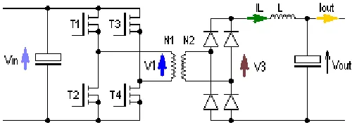
B. Full-bridge DC-DC converter
The full-bridge converter is the most widely used converter configuration for high power fuel cell applications. Full-bridge converter consists of a full-Full-bridge inverter, high frequency transformer, full-Full-bridge rectifier, and input and output filters. A schematic diagram of full-bridge converter is given in Fig. 2.
Fig. 2 Full-bridge converter
The transistors used for the switching purpose are either MOSFETs or IGBTs based on the switching frequency, and the voltage and current ratings of the converter. The output voltage of this converter can be kept constant by adjusting the duty cycle D, where duty cycle is defined for one pair of switches. This converter is mainly used in high power fuel cell applications. The main advantage of this topology is that transistor voltage and current stress are not high with this configuration. The full-bridge converter has small input and output current and voltage ripples. The efficiency of this topology is also high. The cost of full bridge is higher compared to other topologies because full bridge topology requires a complex control system and four switches. The equation of the Full bridge converter in terms of duty cycle is given below.
D
N
N
Vin
Vout
1
2
2
C. Half-bridge converter
converter is that lower winding costs and proximity effect losses. Since half bridge converter has fewer switches than full bridge topology the cost is lower.
Fig. 3 Half-bridge converter
D. Push-pull converter
In the push-pull converter topology, the transformer is used to change the voltage of a DC power supply. Push–pull converters are well known for their simplicity and ability to scale up to high power throughput. The schematic diagram of the push-pull converter is given in Fig. 4. From the below push-pull converter the equation is:
Fig. 4 Push-pull DC/DC converter
Vin
N
N
D
Vout
1
2
2
Where D is the duty cycle of the converter
V. COMPARISON OF THE DC-DC INVERTERS
TABLE2. THE COMPARISION OF DIFERENT DC-DC CONVERTERS
Flyback Full-bridge Half-bridge Push-pull
Advantages can
accommodat e large changes in input voltages
transistor voltage and current stress are not high with this configuratio n
lower winding costs and proximity effect losses
simplicity and ability to scale up to high power throughput
Disadvantages Lower power handling capability and lower efficiency
Requires snubber circuits to guard against spikes
Low efficiency compared to full bridge
Transient response is poor
Power rating Low High Medium Medium
VI.CONCLUSION
Fuel cells are a promising technology. Fuel cell applications bring higher efficiency and lower emission compared to combustion engines. PEMFC is well suited for transportation application whereas MCFC and SOFC are suited for stationary applications. The varying output voltages of the fuel cell can be regulated using a DC-DC converter. Full-bridge topology is ideal for high power applications. The selection of the DC-DC converter topology should be based on power handling capability, transient response, efficiency, transistor voltage and current stress, and input and output ripples.
REFERENCES
[1] IEL Electr. Power Appl., Vol. 1 No. 5 September 2007.
[2] Mohan, Undeland, and Robins. Power Electronics. John Wiley & Sons, INC: 2003. [3] http://en.wikipedia.org/wiki/Image:Push- pull_converter_schematic.svg>
[4] http://www.google.com/search?hl=en&q= push%20pull%20converter&um=1&ie=UTF-8&sa=N&tab=iw> [5] M. H. Rashid. Power Electronics, Circuit devices and applicaions. NJ: Pearson Education 2003.