Article
1
Modular Rotor Single Phase Field Excited Flux
2
Switching Machine With Non-Overlapped Windings
3
Lutf Ur Rahman*, Faisal Khan , Areej Fatima, Muhammad Afzal Khan, Naseer Ahmad, Mohsin
4
Shahzad, Hamid Ali Khan, Hazrat Ali
5
COMSATS University Islamabad, Abbottabad Campus, Pakistan.
6
[email protected], [email protected], [email protected], [email protected],
7
[email protected], [email protected], [email protected], [email protected],
8
* Correspondence: [email protected]
9
10
Abstract: In recent years, numerous topologies of single phase and three phase Field Excited
Flux-11
Switching Machine (FEFSM) have been developed for several applications. Comparative study of
12
three types of single-phase low-priced Field Excited Flux-Switching Machine (FEFSM) is presented
13
in this paper. Both the conventional 8S/4P sub-part rotor design and 6S/3P salient rotor design have
14
an overlapped winding arrangements between armature coil and field excitation coil that depicts
15
high copper losses as well as results in increased size of motor. Additionally, FEFSM with salient
16
structure of the rotor have high flux strength in the stator-core that has much impact on high iron
17
losses. Copper consumption and iron loss being a crucial proportion in total machine losses.
18
Therefore a novel topology of single phase modular rotor field excited FSM with 8S/6P
19
configuration is proposed, which enable non-overlap arrangement between armature coil and FEC
20
winding that facilitates devaluation in the copper losses. The proposed modular rotor design
21
acquires reduced iron losses as well as reduced active rotor mass comparatively to conventional
22
rotor design. It is very persuasive to analyze the best range of speed for these rotors to avoid cracks
23
and deformation, the maximum tensile strength (can be measured with principal stress in research)
24
of the rotor analysis is conducted using JMAG. A deterministic optimization technique is used to
25
enhance the performance of 8S/6P modular rotor design. The electromagnetic performance of
26
conventional sub-part rotor design, F1-A3-3P design and proposed novel-modular rotor design are
27
analyzed by 3D-Finite Element Analysis (3D-FEA), includes flux linkage, flux distribution, flux
28
strength, back-EMF, cogging torque, torque characteristics, iron losses and efficiency.
29
Keywords: Flux switching machine, Modular rotor, non-overlap winding, magnetic flux analysis,
30
iron losses, copper loss, stress analysis, Finite Element Method.
31
32
1. Introduction
33
In everyday application, universal motors are mostly used such as power tools, blenders and
34
fans. They are operated at high speed and deliver high starting torque as getting direct power from
35
ac-grid. At high speed, universal motor causes noise due to their mechanical commutators, and have
36
comparatively short maintenance period. To cope with these snags, research of high performance
37
and low-cost brushless machine is greatly in demand [1].
38
Switched-Flux brushless machines, a new class of electric machine that was first presented in
39
1950s [2]. Flux Switching Machines (FSMs), an unconventional machine originated from the
40
combination of principles among induction alternator and switched reluctance motor [3]. A distinct
41
feature of FSM has high torque density and robust structure of rotor by putting all excitation on stator.
42
In the course of most recent decade various novel FSMs have been developed for several applications,
43
confines from domestic appliances [4], automotive application, Electric vehicles [5], wind power and
44
aerospace [6]. FSM is categorized into Permanent Magnet Flux Switching Machine (PMFSM), Field
45
Excited Flux Switching Machine (FEFSM), and Hybrid Excited Flux Switching Machine (HEFSM).
46
Permanent magnet FSM and Field Excited FSM has permanent magnet (PM) and field excitation coil
47
(FEC) for generation of flux source respectively, whilst both PM and FEC are generation sources of
48
flux in HEFSM. The major advantage of FSM has simple/robust structure of rotor and easy
49
management of temperature rise as all the excitation housed on stator. Recently, use of permanent
50
magnet as a primary source of excitation has dominated in flux switching research, due to its high
51
torque/ high power density and optimum efficiency [7]. However, the maximum working
52
temperature of PM is limited due to potential irreversible demagnetization. The use of PM in not
53
always desirable due to high cost of rare earth material. For low cost applications, it is desirable to
54
reduce the use of permanent magnet and hence is replace by DC-FEC. FEFSM has capable of
55
strengthening and weakening the generated flux as it is controlled by DC-current. FEFSM has
56
disadvantage of less starting torque, fixed rotational direction and high copper losses. The cumulative
57
advantages of both FEC and PM are embedded in HEFSM having high torque capability/high torque
58
density, HEFSM also have high efficiency and flux weakening capability. However, the demerits of
59
HEFSM include more complex structure, saturation of stator-core due to use of PM on stator, greater
60
axial length and having high cost because of rare earth material. Therefore, FEFSM could be
61
considered as better alternative for requirement of low cost, wide speed controllability, high torque
62
density, simple construction, permanent magnet less, and flux weakening operations as compared to
63
other FSMs.
64
Numerous single-phase novel FS machines topologies has been developed for household
65
appliances and different electric means. Single phase FSM was first presented in [8] and further
66
investigated in [9] [10] by C. Pollock, it has 8S-4P doubly salient machine that offers high power
67
density and low cost as shown in Figure 1. The FEC and armature has an overlapped winding
68
arrangements resulting in longer end winding. To overcome the drawback of long end winding,
12S-69
6P FSM has been developed that has same coil pitch as 8 stator slots and 4 rotor poles but shorter end
70
winding [11]. Figure 2. depicts that 12-slots/6-poles machine have fully pitched winding arrangement
71
as C. Pollock design. The end windings effect has even shorter by re-arranging the armature winding
72
and FEC to different pitch of 1 and 3 slot pitches as shown in Figure 3. Both machine having
F2-A2-73
6-pole and F1-A3-6-pole coil pitches have better copper consumption then conventional
machine(F2-74
A2 4pole) for short axial length but has a disadvantage of higher iron loss due to more rotor poles
75
[12]. The stator slots and rotor poles could be halved into F1-A3-3P machine as shown in Figure 4. ,
76
that is much appropriate for high speed because of significant reduction in iron loss. When the axial
77
length is short that is up to 25 mm the average torque of both F2-A2/4P and 6-Pole machine is similar.
78
However, F1-A3/3P exhibit higher average torque than F1-A3/6P machine at longer axial length of 60
79
mm. At the point when end winding is disregarded, the machine having more stator teeth’s and rotor
80
poles has less average torque as compared to machine having less rotor poles and slots of stator for
81
same type of machine.
82
83
(a) (b)
85
(a) (b)
Figure 2. 12S/6P FEFS machine (F2-A2-6P) . (a) cross sectional (b) 3D-model[11]
86
87
(a) (b)
Figure 3. 12S/6P FEFS machine with rearranged winding (F1-A3-6P) . (a) cross sectional (b) 3D-model[11]
88
89
(a) (b)
Figure 4. 6S/3P FEFS machine (F1-A3-6P) . (a) cross sectional (b) 3D-model[11]
90
In single phase FS machine torque is generated with doubly salient structure due to the tendency
91
of rotor to align itself into a minimum reluctance position as shown in Figure 5. When the stator slot
92
and rotor pole is aligned at a minimum reluctance position, the motor couldn’t generate torque (called
93
dead zone torque) at aligned positions unless armature current direction is reversed. Dead zone of
94
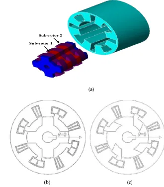
torque is eliminated in [13] with sub-part rotor structure having different pole arc lengths. The
8-95
slots/4-poles sub-part rotors are merged on same face and the pole axes are not parallel. However,
sub-rotor poles can’t be allied with stator slots at a same-time, thus reluctance torque is generated at
97
any rotor position. The single phase 8S/4P sub-part rotor FSM only applicable for a situation that
98
requires a continuous unidirectional rotation. The conventional sub-part rotor design has demerit of
99
overlapped winding arrangements between FEC and armature winding that result in higher copper
100
consumption, and higher iron losses due to salient rotor structure. Single phase sub-rotor FS machine
101
minimize the advantage of high speed, it cannot operate at speed higher than normal level.
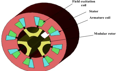
102
This paper presents a novel-modular rotor structure for single phase FS machine as shown in
103
Fig 6. The proposed design comprises of non-overlapped winding arrangements between armature
104
winding and FEC, and modular rotor structure. The consumption of copper is much reduced due to
105
non-overlapped winding arrangements. The modular rotor single phase FSM exhibit a significant
106
reduction in iron losses, also reduces the rotor mass and lower the use of stator back-iron without
107
diminishing in output torque.
108
Sub-rotor 1 Sub-rotor 2
109
(a)
110
111
(b) (c)
Figure 5. Sub-part rotor structure (a) manifestation of sub-part rotor (b) pole arc of sub rotor-1 (c) pole arc
112
of sub rotor-2.
Modular rotor Stator
114
Figure 6. Modular rotor structure.
115
2. Design Methodology
116
The proposed novel modular rotor single phase 8-slots/6-poles FEFSM with non-overlap
117
winding arrangements is presented, as shown in Figure 7. To design the modular structure, JMAG
118
designer ver.14.1 is used and the results obtained are validated by the 3D Finite Element Analysis
119
(3D-FEA). First of all, every section of motor such as stator, rotor, field excitation coil (FEC) and
120
armature coil of modular design with 8-stator slots and 6 rotor poles is designed in the Geometry
121
Editor. Then, the material, mesh properties, circuit, various properties and conditions of the machine
122
is selected and simulated in the JMAG designer. The stainless steel sheet of soft magnetic material
123
35A210, is used for stator and rotor core. The design parameters and specifications of the modular
124
design is illustrated in Table 1.
125
Stator
Armature coil Field excitation
coil
Modular rotor
126
Figure 7. 8S-6P FEFSM with Modular rotor
127
3. Deterministic Optimization
128
The average torque analyses of 8-stator slots/6-rotor poles are examined. The maximum output
129
torque obtained by the initial design is 0.88Nm at speed of 400rpm, which is much lower from the
130
other designs. In order to improve the average torque characteristics, deterministic optimization is
131
used. Design free parameters RIR, θ, SR, TWA, TRA, TWD and TRD are defined in rotor and stator
132
part, as depicts in Figure 8 are optimized, while the outer radius of stator, air gap and shaft of the
133
motor are kept constant. First optimization cycle consists of five steps, that is RIR, θ, SR, TWA, TRA,
134
TWD and TRD.
135
TABLE 1. Design parameter of machines
137
Design Parameters F1-A3-3P Sub-part rotor design
Modular rotor design
Number of phase 1 1 1
No. of slots 6 8 8
No. of pole 3 4 6
Stator outer diameter 96 mm 96 mm 96 mm Rotor outer diameter 55.35mm 53.55 mm 53.55 mm
Air-gap 0.45 0.45 mm 0.45 mm
Rotor inner diameter 21 mm 10 mm 20 mm Stator pole arc length - 15.2 mm 5.5 mm Teeth’s arc of sub-rotor-1 - 15.2 mm - Teeth’s arc of sub-rotor-2 - 26.9 mm -
Rotor pole width 8 mm - 5.6 mm
Stack length 60 mm 60 mm 60 mm
No. of turns per phase 120 30 30
Initially, the design free parameters of rotor is updated, first of all, the inner rotor radius, RIR,
138
are change while the keeping other parameters of stator and rotor are constant. Then, rotor pole angle,
139
θ, and split ratio Ss, are varied and adjusted. The rotor pole angle, θ, is a dominant parameter in
140
modular design to increase torque characteristics. Once the combination of promising values of rotor
141
part for highest average output torque is determined, the next step is to refine the TWD and TRD of
142
FEC, while rotor and armature slot parameter are kept constant. Finally, the essential armature slot
143
is optimized by changing TWA and TRA while all other design parameters are preserved. To attain
144
the highest average output torque, the above design optimization process is repeated. Figure 9.
145
illustrates the highest average torque result after two cycles of optimization by updating several
146
parameters that is already mentioned above. From Figure 9, it is also clear that during the first cycle
147
the torque increases to a certain level by varying above parameters of machine and formerly becomes
148
constant.
149
During the first cycle, 32 percent of increase in the average output torque is achieved by refining
150
the dominant parameter of rotor pole angle, θ, whilst other free design parameter adjustment show
151
a less improvement in torque. In comparison with the initial design the average output torque is
152
improved by 40 percent after completion of second optimization cycle. The initial and optimized
153
structure of 8S/6P modular design is illustrated in Figure 10. Additionally, the comparison of
154
parameters of initial and final design is presented in Table 2.
155
Table 3. depicts comparison of cogging torque, flux linkage, back-EMF, average torque, and power
156
of 3D-modular un-optimized and optimized design. The cogging torque and flux linkage of
157
optimized designs is 0.3374Nm and 0.2114Wb respectively, which is 50% lower than the
un-158
optimized cogging torque and flux linkage. Whilst, back-EMF of optimized modular 8S/4P is
159
improved by 15%, that is still much lower than the applied input voltage of 220V. Furthermore,
160
before optimization of modular design the maximum average output torque and power obtained is
161
9.77Nm and 162.9Watts respectively, at maximum FEC current density, Je, is set to 10A/mm2 and
162
25A/mm2 is assigned to the armature coil, which is improved to 1.66Nm and 288Watts, respectively.
163
Comparatively, average output torque and power is improved by 58.85% and 56.40%, respectively.
166
Figure 8. Design parameters of modular rotor design. Figure 9. Effect of design parameters on average torque
167
168
(a) (b)
Figure 10. Structure of 8-slots/6-poles modular design.
169
Table 2. Initial and refined design parameters of Novel-modular rotor design
170
Parameters Units Initial
values
optimized
values
Outer stator (OS) mm 48 48 Inner stator (IS) mm 27 24.7 Back-iron width of AC (TRA) mm 42.5 41.4
Tooth width of AC (TWA) mm 7.6 7.5
Back-iron width of DC (TRA) mm 42.5 38.66
Tooth width of DC (TWD) mm 7.6 5.5
Rotor inner circle radius (RIR) mm 10 9.7
Pole shoe width (PSW) mm 3 3
Rotor pole angle ( ) deg 45 36 Split ratio (SR) - 0.55 0.5
Air gap mm 0.45 0.45
Shaft radius mm 10 10
Avg. torque Nm 0.880 1.454
171
0 0.1 0.2 0.3 0.4 0.5 0.6 0.7 0.8 0.91 1.1 1.2 1.3 1.4 1.5 1.6
A
v
g
. t
o
rq
u
e,
(
N
m
)
Parameters
RIR SR TWA TWD RIR SR TWA TWD
Table 3. Results comparison of optimized and un-optimized design
172
--
Cogging
torque
(Nm)
Flux
linkage
(Wb)
Back-EMF
(volt)
Avg. Torque
(Nm)
Power
(Watts)
Un-optimized
design 0.67 0.01060 3.9 0.97775 162.986
Optimized
design 0.3374 0.02114 4.6 1.66148 288.967
4. Result And Performance Based On 3D-FEA Finite Element Analysis (3D-FEA)
173
4.1. Flux Linkage
174
Comparison of flux linkages of three field excited FSM at no-load is validated by 3D-FEA. To
175
analyze the sinusoidal behavior of flux, the input current density of FEC and armature coil is fixed to
176
10 A/mm2 and 0 A/mm2 respectively. Figure 11. shows that proposed modular design has peak flux
177
of 0.021Wb which is approximately equal to the peak flux of 15% of F1-A3-3P design. Similarly,
sub-178
part rotor design has 66% higher peak flux linkage than 8S/6P modular structure due to different pole
179
arc length. The conventional F1-A3-3P design has highest peak flux as compared to modular design
180
as well as sub-part rotor design due to the doubly salient structure.
181
182
Figure 11. Comparison of U-flux linkages.
183
4.2. Flux Distribution
184
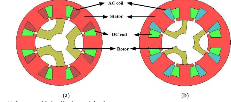
Flux density distribution generated by the DC coil in three FEFSM is shown in Figure 12. The
185
red spot mention in Figure 12 (a) and (c) show saturation of stator teeth and back-iron respectively
186
of both conventional designs. F1-A3-3P design and sub-part rotor design has vector plot value of
187
magnetic flux density distribution of 1.9953 and 1.9760 maximum, respectively. Whilst, the flux
188
density distribution of modular design from the vector plot is 2.2528 maximum at 0° rotor position.
189
Additionally, in comparison with 8S/4P sub-part rotor design and 6S/3P design, the proposed 8S/6P
190
modular rotor design exhibits higher flux distribution. For completely utilizing flux in the proposed
191
design, various parameters of machine is optimized to enhance the flux distribution from stator to
192
rotor and vice versa.
193
194
-0.2
-0.15
-0.1
-0.05
0
0.05
0.1
0.15
0.2
0
60
120
180
240
300
360
F
lu
x,
Wb
Electrical degree
F1-A3-3P
Sub-Part rotor
195
(a) (b)
196
(c)
Figure 12. Flux Distribution (a) Flux distribution conventional in F1-A3-3P design (b) Flux distribution in
197
sub-part rotor design (c) Flux distribution in proposed modular rotor design
198
4.3. Flux Strengthening
199
The effect of flux strength is analyzed by increasing current density; Je of field excitation coil
200
(FEC) is varied from 0 A/mm2 to 20 A/mm2, whilst armature current density; Ja is set 0 A/mm2. The
201
FEC input current is calculated from “(1)”.
202
= (1)
203
Where, Ie, Je, , Se and Ne are the input current of FEC, field current density, filling factor, slot area
204
of FEC, and number of turns of field coil respectively. The analysis of coil test can be verified from
205
the flux strengthening. With increasing the current densities of FEC the pattern plot clearly shows a
206
linear increase in flux until 0.027 Wb at Je of 20 A/mm2 as shown in Figure 13.
208
Figure 13. Peak flux strengthening with Modular rotor at various Je
209
4.4. Back-EMF Versus Speed
210
“Back-EMF is the induce voltages in the armature winding which opposes the change in current
211
through which it is induced”. The back-EMF (ea) in the armature can be determined from the rate of
212
change in armature flux or applying the co-energy concept [14]. For motor with Nr rotor poles
213
= 2 (2)
214
Where , , , , and is number of armature turns, number of rotor poles, rotational
215
speed, field flux and constant of field flux that linking with armature winding respectively.
216
Substituting the (field flux) with
217
=
ℛ (3)
218
=2
ℛ (4)
219
Where , and ℛ is the number of field turns, the field current and reluctance of magnetic
220
circuit. For the maximum conversion of electro-mechanical energy, armature current must flow in
221
opposite direction to the induced-EMF in armature.
222
Figure 14. shows the 3D-FEA predicted induced-EMF of 8-slots/6-poles modular rotor structure
223
at a fixed field current density (Je; 10A/mm2 ) and various speed. The induced-EMF is increases
224
linearly with increasing speed. The maximum induced voltage is 22V at a maximum speed of
225
1600rpm which is quiet lower than the applied input voltage (220V) which confirm the motor
226
actioning of machine.
227
0
0.01
0.02
0.03
0
5
10
15
20
F
lu
x,
Wb
228
Figure 14. Maximum back-EMF at various speed
229
4.5. Total Harmonic Distortion(THD)
230
Total harmonics distortion is the ratio of the summation of all harmonic components to the
231
fundamental frequency harmonics of the power or can say harmonics distortion that exists in signal.
232
In electric machines, THD occurs due to harmonics present in flux. THD determines the
233
electromagnetic performance of the machine as it is the representation of the harmonics in the
234
machine. Mathematically THD of electric machine can derived from equation (5)
235
=
∑ , …
(5)
236
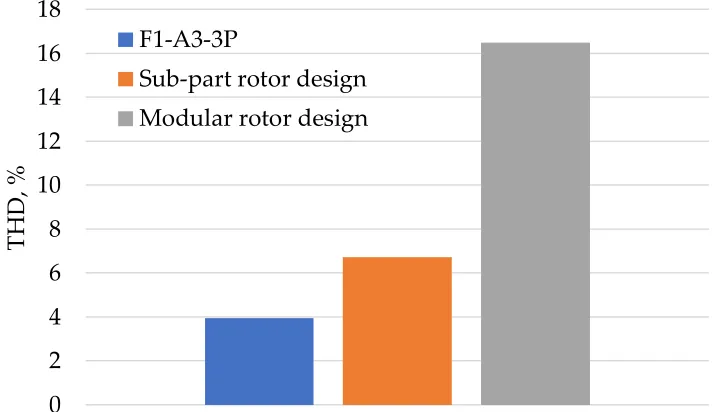
Where k is odd number and is the odd harmonics of flux. THD of proposed design is higher
237
as compare to conventional design due to the modular structure of rotor. Figure 15 shows the THD
238
of three FEFS machine. The graph shows that the THD of sub-part rotor design and F1-A3-3P design
239
is 7% and 4% respectively, while THD of proposed modular rotor design is 16.4%.
240
241
Figure 15. THD values of conventional and proposed design.
242
243
0
5
10
15
20
25
0
400
800
1200
1600
E
M
F,
V
Speed, rpm
0
2
4
6
8
10
12
14
16
18
T
H
D
, %
F1-A3-3P
Sub-part rotor design
4.6. Cogging Torque
244
The interaction between the Stator excitation source (PM, excitation coil) and rotor pole of
245
machine at no-load is called cogging torque. Magnetic circuit consists of an existing PM and coil
246
having co-energy, the total co-energy is formulated as [15-16].
247
= +1
2( + (ℛ + ℛ ) ) (6)
248
Where, , , ℛ , , ℛ and are the number of turn, current, magnetic field, inductance of
249
coil, magneto-motive force and magnetic flux linkage respectively. The change in total co-energy with
250
respect mechanical angle of rotor determine the average torque of the machine.
251
= ℎ = (7)
252
Where, and are total co-energy and mechanical rotor angle and respectively.
253
= ( +
1
2( + (ℛ + ℛ ) ) )
254
= + 1
2 −
1 2
ℛ
(8)
255
The 3rd term in eq. (8) change in mmf w. r. t mechanical position of rotor causes cogging torque.
256
The cogging torque produces unwanted noise and vibration. As the eq (8) shows that the cogging
257
torque lead to a significant reduction in the average torque.
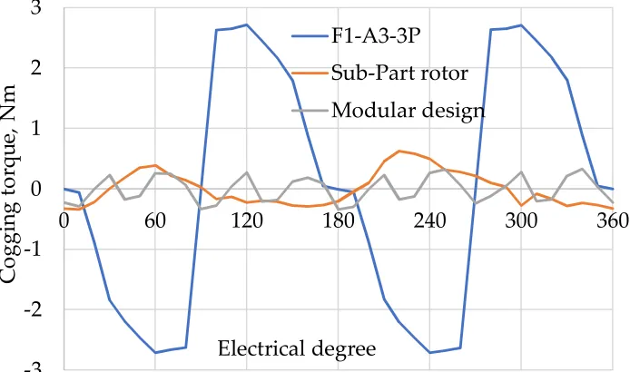
258
The cogging torque of F1-A3-3P, Sub- part rotor and modular designs is compare in Figure 16.
259
The cogging of Modular design is less than F1-A3-3P and Sub- part rotor designs as depicts in Figure
260
16. Figure 16. Illustrates that the cogging torque of modular design is 12% of F1-A3-3P and 53% of
261
Sub- part rotator. As a result the modular design has less vibration and more average torque as to
262
compare to F1-A3-3P and Sub-part rotator design.
263
264
Figure. 16 Comparison of Cogging torque
265
266
267
-3
-2
-1
0
1
2
3
0
60
120
180
240
300
360
C
o
g
g
in
g
t
o
rqu
e,
N
m
Electrical degree
F1-A3-3P
Sub-Part rotor
4.7. Copper Loss Vs Torque
268
In field excited FSM, the copper consumption is the main constituent affecting the overall cost
269
of the machine. As compare to other material of FEFSM copper is more expensive. The copper-loss
270
of single phase FEFSM can be calculated from the formula as;
271
= + (9)
272
Where Ia, Ra, If, Rf is the armature current, armature winding resistance, field current, field
273
winding resistance respectively. The comparison of copper loss-torque curve of three field excited
274
FSM is shown in Figure 17. The average output torque modular design is almost similar to the
sub-275
part rotor design but is much higher than the F1-A3-3P design. At fixed copper loss of 60 watt the
276
average torque of conventional sub-part rotor design, F1-A3-3P design and proposed modular design
277
is 1.6 N-m, 0.98 N-m and 1.58 N-m respectively. However, the plot clearly shows that modular design
278
achieve higher average torque under constraint of maximum copper loss of 120 watt due to the short
279
pitch coils.
280
281
Figure. 17 Comparison of average torque at fixed copper losses.
282
4.8. Torque Density And Power Density
283
Torque density and power density of three FEFS machine is calculated at fixed current density
284
of 10A/mm2. Figure 18. illustrates torque densities of sub-part rotor design, F1-A3-3P design and
285
modular rotor design. Comparatively, torque density of F1-A3-3P design is 1.89 times higher than
286
modular rotor design and 1.71 times higher than sub-part rotor design as shown in Figure 18.
287
The power density of conventional and proposed design is expressed in Figure 19. Power
288
density attains by modular rotor design is 0.0783Watt/kg at current density of FEC,JE, and armature
289
current density, JA, of 10A/mm2 as shown in Figure 19. High power density exhibits high efficiency
290
and better electromagnetic performance. The proposed 8S/4P modular rotor design achieve 1.3 and
291
1.9 times higher power densities as compared to F1-A3-3P design and sub-part rotor design
292
respectively.
293
0
0.5
1
1.5
2
2.5
0
20
40
60
80
100
120
A
v
g
.t
o
rqu
e,
N
m
Copper Loss, watt
F1-A3-3P
294
Figure 18. Torque density of three FEFS machines
295
296
Figure 19. Power density of three FEFS machines
297
4.9. Torque And Power Versus Speed Characteristics
298
The comparison of torque and power versus speed curve of three single phase FEFSM are
299
illustrated in Figure 20. At rated speed of 1664rpm, the maximum average torque of modular rotor
300
design is 1.64Nm which correspond to the power generated by the proposed design is 286W.
301
Additionally, the average torque obtained by conventional 8S-4P sub part rotor design and 6S-3P
302
salient rotor is 1.4Nm and 3.77Nm, at a base speed of 1389rpm and 1053rpm, respectively. The
303
average torque of proposed design is higher as compared to the sub part rotor design. At speed of
304
1600rpm, the average torque of proposed design is similar to 6S-3P design while 19 percent higher
305
than 8S-4P design. Although, the generated power of 8S-6P modular design is 28.4 percent higher
306
than 8S-4P design, while 31 percent lower than F1-A3-3P design. The pattern plot shows that beyond
307
rated speed average torque of the machine starts to decrease and power is decreased as well. The
308
power of 6S-3P FEFSM decreases more rapidly due to increase in iron loss above the rated speed.
309
0
0.1
0.2
0.3
0.4
0.5
0.6
T
o
rqu
e
d
en
si
ty
,
N
m
/k
g
F1-A3-3P
Sub-part
Modular
0
0.01
0.02
0.03
0.04
0.05
0.06
0.07
0.08
0.09
P
o
w
er
d
en
si
ty
,
w
at
t/k
g
310
Figure 20. Comparison of torque/power versus speed of three FEFSM. (The dotted lines in the plot shows
311
the power curve, while solid line depicts the torque curve at various speed)
312
4.10. Rotor Stress Versus Speed
313
Rotor stress analysis is a technique to identify the principal stress, nodal force and displacement
314
occurred in the rotor structure in an ideal state after load is applied. Generally, condition for
315
mechanical stress of the rotor structure is accomplished by centrifugal force due to the longitudinal
316
rotation of rotor. Additionally, centrifugal force of the rotor is greatly affected with the speed. Rotor
317
could highly withstand to the stress, if the principal stress of the rotor is higher. Principal stress is a
318
crucial result in the analysis of stress. With increasing the angular velocity of the rotor principal stress
319
is increased exponentially. Thus, the rotor principal stress verses speed of the three field excited flux
320
switching machines (rotor structure) is analyzed using 3D-FEA. The angular velocity varies from
321
0rpm to 20000rpm for conventional three pole salient rotor structure, four pole sub-part rotor
322
structure and proposed 6 poles modular structure to analyze the maximum capability of mechanical
323
stress. The constraints that coincide to the force acting on the rotor is faces, edges and vertices.
324
Positions of the constraints for each rotor structure are different as shown in Figure 21, 22, and 23.
325
326
(a) (b) (c)
Figure.21 Direction of constraints for salient rotor structure
327
328
(a) (b) (c)
Figure. 22 Direction of constraints for modular rotor structure
329
0
100
200
300
400
500
0
1
2
3
4
0
500 1000 1500 2000 2500 3000 3500 4000 4500
P
o
w
er
, w
at
t
T
o
rqu
e,
N
m
Speed, rpm
330
(a) (b) (c) (d)
Figure 23. Direction of constraints for sub-part rotor structure.
331
Figure 24 shows that comparison of principal stress of three different rotor structures versus
332
speed. At maximum speed of 20000rpm, the principal stress of salient rotor structure, sub-part rotor
333
structure and modular rotor structure is 6.73MPa, 11.61MPa and 2.11MPa respectively. The pattern
334
plot clearly shows that principal stress of proposed modular rotor structure is much lower as
335
compared to the conventional rotor design. The maximum allowable principal stress of 35H210
336
electromagnetic steel is 300MPa. All the three rotor structures are capable for high speed application,
337
but only salient rotor structure can be operated at high speed due to the single piece rotor structure.
338
Whilst, sub-part rotor and modular structure is only applicable for low-speed applications.
339
340
Figure 24. Principal Stress against speed
341
4.11. Copper Losses Versus JE At Various JA
342
Copper losses of three FEFSM at various armature current densities is shown in Figure 25. To
343
analyze the total copper losses, FEC current density, JE, is set to 10A/mm2, and armature current
344
density is varied from 0A/mm2 to 25A/mm2. The pattern plot clearly showed that the copper losses is
345
increased with increasing current densities. Comparatively, proposed modular rotor design shows
346
approximately 56% and 88% lower copper losses to sub-part rotor design and F1-A3-3P design
347
respectively, at maximum armature current density of 25A/mm2. However, the proposed structure
348
has reduced copper losses indicating improved efficiency than the conventional designs.
349
0
2
4
6
8
10
12
14
0
5000
10000
15000
20000
P
ri
n
ci
pal
s
tr
es
s,
M
P
a
Speed, rpm
F1-A3-3P
350
Figure 25. Copper losses versus various JA
351
4.12. Iron Loss Versus Speed
352
Iron loss is a significant portion in the total losses of machine. Machine performance is greatly
353
affected by iron losses due to flux emphasis of novel-modular topology in the stator, which generates
354
variation of flux densities in the rotor and stator core [17, 18]. The flux density variation is expected
355
to reduce by implementing the novel-modular topology due to the reduction in utilization of stator.
356
Iron losses are increased with increasing electrical loading due to higher armature reaction [19]. The
357
iron losses of switched flux machine also greatly varying with speed as shown in Figure 26. At
low-358
speed, machine dominates over electromagnetic losses. The method of iron loss calculation can be
359
found in [17, 20].
360
The iron loss of each component of three field excited FSM is calculated by 3D-FEA. In Figure
361
26. the plot clearly shows that the proposed modular rotor structure has lowest iron loss then the
362
conventional sub-part rotor design and F1-A3-3P design. At maximum speed of 4000 rpm, modular
363
design reduces the iron losses of 29.44% and 7.22% compared with the conventional F1-A3-3P design
364
and sub-part rotor design respectively. The reason of iron loss reduction in the stator due to modular
365
rotor, and variation of flux densities in the stator-core is investigated in [21].
366
367
Figure 26. Comparison of iron losses at various speed
368
369
0
50
100
150
200
250
300
5
10
15
20
25
C
o
pper
L
o
ss
es
, W
at
ts
Armature current density, Ja
Modular design
Sub-Part rotor
F1-A3-3P
0
20
40
60
80
100
120
140
0
1000
2000
3000
4000
Ir
o
n
l
o
ss
, w
at
t
Speed, rpm
F1-A3-3P
Sub-Part rotor
4.13. Motor Losses And Efficiency Analysis
370
The efficiency of three FEFSM is computed by 3D-FEA, considering all motor losses (iron losses
371
in core laminations and copper losses in FEC and armature coil). Copper losses(Pcu) is calculated at
372
fixed current densities of 10A/mm2, for both FEC, Je, and armature coil, Ja, for all designs. Whilst, the
373
iron losses is calculated at varying speed of 1000-4000rpm. In single phase FEFS machine copper
374
losses can be illustrated as
375
= + (10)
376
Where Pcu, If, Rf, Ia and Ra are copper losses, field current, total field coil resistance, armature
377
current and total armature coil resistance, respectively. Figure 27 (a)(b)(c) shows iron losses(Pi) ,
378
copper losses(Pcu), output power(Po) and efficiency at different speed(range: 1000-4000rpm) of
379
Sub-part rotor design, F1-A3-3P design and modular rotor design respectively. However, with
380
increasing speed the iron losses is increases as well that further degrade efficiency. Furthermore, at
381
every operating speed from 1000rpm to 4000rpm, the proposed design achieve comparatively higher
382
efficiencies. At max speed of 4000rpm, the iron losses of proposed modular rotor design is 9% and
383
30% lower than the conventional sub-part rotor design and F1-A3-3P design respectively. However,
384
reduction in iron losses shows a significant reduction in total machine losses, approximately 49% of
385
F1-A3-3P design and 15% of sub-part rotor design. Furthermore, by adopting the modular structure
386
the proposed 8S/6P design achieves higher average efficiency of approximately 12.8% and 11.4%
387
higher than the conventional F1-A3-3P and sub-part rotor design, respectively. Finally, it can be seen
388
from Figure 28, the efficiency of single phase modular 8S/4P FEFS machine exhibit higher efficiency
389
than other conventional FEFS machines.
390
391
Figure 27(a). Losses and efficiency of sub-part rotor design at various speed.
392
0%
20%
40%
60%
80%
100%
1000
2000
3000
4000
E
ff
ic
ien
cy
,
%
Speed, rpm
393
Figure 27(b). Losses and efficiency of F1-A3-3P design at various speed.
394
395
Figure 27(c). Losses and efficiency of modular rotor design at various speed.
396
397
Figure 28. Comparison of efficiency at various rotor speed.
398
0%
20%
40%
60%
80%
100%
1000
2000
3000
4000
E
ff
ic
ien
cy
,
%
Speed, rpm
Po
Pi
Pcu
0%
20%
40%
60%
80%
100%
1000
2000
3000
4000
E
ff
ic
ien
cy
,
%
Speed, rpm
Po
Pi
Pcu
0
20
40
60
80
100
0
1000
2000
3000
4000
E
ff
ic
ien
cy
,
%
Speed, rpm
Sub-part rotor
F1-A3-3P
5. Conclusion
399
A novel single phase field excited topology of modular rotor flux switching machine is presented
400
and the result is validated by 3D-FEA.
401
In this paper comparison of three single-phase 8-slots/4-pole sub rotor design and 6-slots/3-poles
402
salient rotor design with novel modular rotor 8-slots/6-poles FSM is demonstrated. For pair
403
comparison of flux linkage, cogging torque, average torque and other different analysis of proposed
404
FEFSM, optimal split ratio is set identical to the conventional designs.
405
Proposed novel modular 8S/6P single phase FSM with non-overlapped winding arrangement is
406
designed. Copper consumption of modular rotor design is much lower than conventional designs
407
due to non-overlap winding between FEC and armature coil. The proposed design shows a higher
408
average output torque when compared under constraints of fixed copper losses. Modular rotor
409
structure also exhibits a significant reduction in iron losses. Due to the modular structure of rotor,
410
the active rotor mass of the proposed design is reduced and lower the use of stator back-iron without
411
diminishing in output torque. This paper also examines the principal rotor stress of the conventional
412
rotor designs (sup-part rotor design and 3-pole salient rotor design) and proposed (modular) rotor
413
design with a different direction of constraints. Additionally, modular rotor design has higher
414
average efficiency as compare to conventional designs, due to considerable reduction in copper losses
415
as well as iron losses.
416
References
417
1. You, Zih-Cing, Sheng-Ming Yang, Chung-Wen Yu, Yi-Hsun Lee, and Shih-Chin Yang. "Design of a High
418
Starting Torque Single-Phase DC-Excited Flux Switching Machine." IEEE Transactions on Industrial
419
Electronics, 2017, vol 64, pp. 9905-9913.
420
2. Khan, Faisal, Erwan Sulaiman, and Md Zarafi Ahmad. "A novel wound field flux switching machine with
421
salient pole rotor and nonoverlapping windings." Turkish Journal of Electrical Engineering & Computer
422
Sciences, 2017, vol 25, pp. 950-964.
423
3. Omar, M. F., E. Sulaiman, M. Jenal, R. Kumar, and R. N. Firdaus. "Magnetic Flux Analysis of a New
Field-424
Excitation Flux Switching Motor Using Segmental Rotor." IEEE Transactions on Magnetics 2017,vol 53, pp.
425
1-4.
426
4. Zhu, Z. Q., and J. T. Chen. "Advanced flux-switching permanent magnet brushless machines." IEEE
427
Transactions on Magnetics 2010,vol 46, pp. 1447-1453.
428
5. Sangdehi, SM Kazemi, S. E. Abdollahi, and S. A. Gholamian. "A segmented rotor hybrid excited flux
429
switching machine for electric vehicle application." In Power Electronics, Drive Systems & Technologies
430
Conference PEDSTC, 2017, pp. 347-352.
431
6. Sanabria-Walter, C., H. Polinder, J. A. Ferreira, P. Jänker, and M. Hofmann. "Torque enhanced
flux-432
switching PM machine for aerospace applications." In Electrical Machines ICEM, 2012, pp. 2585-2595.
433
7. Chen, Yu, Z. Q. Zhu, and David Howe. "Three-dimensional lumped-parameter magnetic circuit analysis
434
of single-phase flux-switching permanent-magnet motor." IEEE Transactions on Industry
435
Applications 2008, vol 44, pp. 1701-1710.
436
8. Rauch, S. E., and L. J. Johnson. "Design principles of flux-switch alternators." Transactions of the American
437
Institute of Electrical Engineers Power Apparatus and Systems, 1955,vol 74, pp. 1261-1268.
438
9. Pollock, H., C. Pollock, R. T. Walter, and B. V. Gorti. "Low cost, high power density, flux switching
439
machines and drives for power tools." In Industry Applications Conference, 2003, vol. 3, pp. 1451-1457.
440
10. Pollock, C., H. Pollock, and M. Brackley. "Electronically controlled flux switching motors: A comparison
441
with an induction motor driving an axial fan." In Industrial Electronics Society IECON, 2003, vol. 3, pp.
442
2465-2470.
443
11. Zhou, Y. J., and Z. Q. Zhu. "Comparison of low-cost single-phase wound-field switched-flux machines."
444
IEEE Transactions on Industry Applications, 2014, vol 50, pp. 3335-3345.
445
12. Pang, Y., Z. Q. Zhu, D. Howe, S. Iwasaki, R. Deodhar, and A. Pride. "Investigation of iron loss in
flux-446
switching PM machines, 4th IET International Conference on Power Electronics, Machines and Drives (PEMD),
447
2008, pp. 460-464.
448
13. Zhang, Zongsheng, Xu Tang, Daohan Wang, Yubo Yang, and Xiuhe Wang. "Novel Rotor Design for
Single-449
Phase Flux Switching Motor." IEEE Transactions on Energy Conversion, 2018, vol 33, pp. 354-361
14. Zulu, Ackim, Barrie C. Mecrow, and Matthew Armstrong. "A wound-field three-phase flux-switching
451
synchronous motor with all excitation sources on the stator." IEEE transactions on industry
452
applications 2010, vol 46, , pp. 2363-2371.
453
15. Zhu, Li, S. Z. Jiang, Z. Q. Zhu, and C. C. Chan. "Analytical methods for minimizing cogging torque in
454
permanent-magnet machines." IEEE transactions on magnetics, 2009, vol 45, pp. 2023-2031.
455
16. Abdollahi, Seyed Ehsan, and Sadegh Vaez-Zadeh. "Reducing cogging torque in flux switching motors with
456
segmented rotor." IEEE Transactions on Magnetics 2013, vol 49, pp. 5304-5309.
457
17. Pang, Y., Z. Q. Zhu, D. Howe, S. Iwasaki, R. Deodhar, and A. Pride. "Investigation of iron loss in
flux-458
switching PM machines." 2008, pp. 460-464.
459
18. Hoang, Emmanuel, Mohamed Gabsi, Michel Lécrivain, and Bernard Multon. "Influence of magnetic losses
460
on maximum power limits of synchronous permanent magnet drives in flux-weakening mode." In Industry
461
Applications Conference, 2000. Conference Record of the 2000 IEEE, vol. 1, pp. 299-303.
462
19. Chen, J. T., Z. Q. Zhu, S. Iwasaki, and R. Deodhar. "Comparison of losses and efficiency in alternate
flux-463
switching permanent magnet machines." In Electrical Machines (ICEM), 2010 XIX International Conference
464
on, IEEE 2010, pp. 1-6.
465
20. Calverley, Stuart David, G. W. Jewell, and R. J. Saunders. Design of a high speed switched reluctance
466
machine for automotive turbo-generator applications. No. 1999-01-2933. SAE Technical Paper.
467
21. Thomas, A. S., Z. Q. Zhu, and L. J. Wu. "Novel modular-rotor switched-flux permanent magnet
468
machines." IEEE Transactions on Industry Applications 48, 2012, vol no. 6, pp. 2249-2258.
![Figure 2. 12S/6P FEFS machine (F2-A2-6P) . (a) cross sectional (b) 3D-model[11]](https://thumb-us.123doks.com/thumbv2/123dok_us/8023007.1334560/3.595.86.516.76.256/figure-s-p-fefs-machine-cross-sectional-model.webp)