IJEDR1401062
International Journal of Engineering Development and Research (www.ijedr.org)357
Realization of Neural Network for Pattern Detection
using VHDL
Mr.Tanmay Bhavsar,
PG student (EC)S.P.C.E, Visnagar -Gujarat-India [email protected]
______________________________________________________________________________________________________ Abstract— Artificial Neural Network is attempts to mimic, at least partially, the structure and function of brain and nervous system. Advances in VLSI technology and demand for intelligent machines have created strong resurgence of interest in emulating neural system for real time applications. Such an Artificial Neural Network can be built with help of basic universal gates, flip-flops and other digital circuits to design multiplier, activator and pattern detector. This paper gives information about Neuron behavior and how it takes intelligent decision and how Neuron can be implemented to detect various character or digits. Using Neural Network, we can detect digits and display them on seven segments elements with the help of VHDL.
Key words—ANN, AI, FPGA, VHDL
I.INTRODUCTION
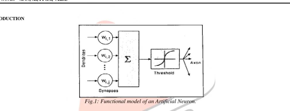
Fig.1: Functional model of an Artificial Neuron.
The Artificial Intelligence has spurred research on Neuron Network on last few years. Current AI technology based on knowledge based expert system is relying heavily on symbolic manipulation. Major limitation is that knowledge based is static set of rules cast by human experts. At inevitable error prone interface between the human experts and AI programmers must cope with fuzzy information.
Artificial intelligent Neural Networks on other hand are trained by successive examples in real world environment. As ANN adapt to the changes in their environment. They develop their own internal rules. One advantage of Artificial Neural Network is their ability to handle fuzzy or incomplete data.
II.BASICBUILDINGOFARTIFICIALNEURON
Fig. 2: The schematic of Artificial Neural Network.
IJEDR1401062
International Journal of Engineering Development and Research (www.ijedr.org)358
intelligence Artificial Neurons are used. Design and VHDL implementation of Neural Network Architecture for Signal Processing is experienced in Xilinx8.1. These Artificial Neurons, in this paper are realized by digital circuits like multipliers, adders, Neuron activation function (linear function). The Neuron selected in this paper comprises of multiplier and adder along with the linear activation function. Neuron architecture is performed in the digital domain.III. REALIZATION OF NEURAL NETWORK ARCHITECTURE USING VHDL
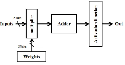
The inputs to the Neuron as shown in figure 2 are multiplied by the weight matrix, the resultant output is summed up and is passed though Neuron activation function (NAF). The output obtained from the activation function is taken through the next layer for further processing. The multiplier block, adder block and the activation function create the model of Artificial Neural Network. Blocks to be analyzed are as follows:
1. Artificial Neuron Design
2. Neural Architecture with Feed Forward System 1. Artificial Neuron Design
In this section, there are 2 major parts: data structure and digital modules for Neuron design on FPGA. For design tools, Modelsim simulates the design at multiple stages throughout the design process and Xilinx programs the board are used. Generally, a data structure is a particular way of storing and organizing data in a computer so that it can be used efficiently. Data structures are generally based on the ability of a computer/chip to fetch and store data at any place in its memory, specified by an address that can be manipulated by the program. For this project, the data computed from ADC will be converted into fixed-point number representation.
Fixed-point DSPs use 2‟s complement fixed-point numbers in different Q formats. The major issues in data structure is the conversion technique of fixed-point number from a Q format to an integer value so that it can be stored in memory and recognized by simulator. Keeping track of the position of the binary point is also required while manipulating fixed- point numbers in writing VHDL codes. The number is first normalized then scaled down by 2 to the appropriate value that can be accommodated by the bits number. Finally, the value will be rounded (truncated) to integer value and represented in binary number too. A Neuron can be viewed as processing data in three steps; the weighting of its input values, the summation of all and their filtering by a activation function. The Neuron can be s
Where y is the output of the Neuron, w is the synaptic weight, x is the input and θ is the bias. The subscript i denote the preceding Neuron while j the Neuron considered. The Neuron computes the product of its inputs, with the corresponding synaptic weights, and then the results are added. The result is presented to a comparison unit designed to represent an appropriate activation function such as linear, sigmoid or hyperbolic tangent.
The block diagram of the hardware implementation is shown in Fig. 3. Input & weight consist of N bits (in our case N=4 bit) which are multiplied with shift and add multiplier. For each Neuron there are two sub input which are used for accuracy of measurement to each pattern portion. Resulting output is feed to activation function. Among all available activation functions like as tangential hyperbolic, sigmoid or linear we had used linear activation i.e. just activating Neuron if greater than threshold. Result of respective activation block will generate 1 bit output signal to activate Neuron.
Fig. 3(A): Schematic of Artificial Neuron
2 Artificial Neural Networks (ANNS) With Feed Forward System
Artificial Neural Networks (ANN‟s or simply NN‟s) are inspired by biological nervous systems and consist of simple processing elements (PE, Artificial Neurons) that are interconnected by weighted connections. The predominantly used structure is a single layered feed-forward Network ( perceptron), i.e., the nodes (Neurons) are arranged in several layers (input layer, hidden layers, output layer etc.), and the information flow is only between adjacent layers. An Artificial Neuron is a very simple processing unit. It calculates the weighted sum of its inputs and passes it through a nonlinear transfer function to produce its output signal. The predominantly used transfer functions are so-called sigmoid” or “squashing” functions that compress an infinite input range to [-1, 1]. Neural Networks is “trained” to solve problems that are difficult to solve by conventional computer
IJEDR1401062
International Journal of Engineering Development and Research (www.ijedr.org)359
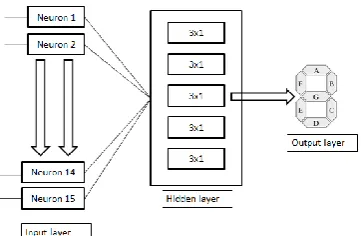
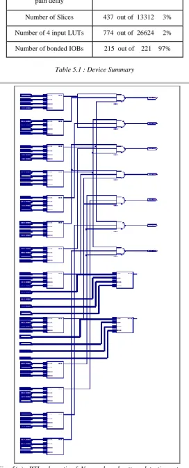
algorithms. Training refers to an adjustment of the connection weights, based on weighting algorithms. Here we had used 15 Neurons to construct architecture of Neurons which forms input layer of Network. Each 3 Neurons are grouped together to make a respective segment of seven segment LED which function as hidden layer as well as processing element and output layer respectivelyFig-3(B): architecture of 15x7 Neuron Network
When we speak of intelligence it is actually acquired, learned from the past experiences. This intelligence, though a biological word, is realized based on the mathematical equations, giving rise to the science of Artificial Intelligence (AI).To implement this intelligence Artificial Neurons are used. Design and VHDL implementation of Neural Network Architecture for Signal Processing is experienced in Xilinx8.1. These Artificial Neurons, in this paper are realized by digital circuits like multipliers, adders, Neuron activation function (linear function).
The Neuron selected in this paper comprises of multiplier and adder along with the linear activation function. Neuron architecture is performed in the digital domain.
IV.PATTERN DETECTION
If the input patterns are the decimal digit from zero to nine, then it should be displayed using the seven segment display, kinds of display unit shown in Fig. 4.3. In Fig 4.3, the numbers „a‟ to „g‟ denotes as units of the seven segment display. Properly activating and deactivating these seven displaying units, we can display the decimal digits one to nine. In this section, we discussed about a simple image pattern recognition example and 5x3 matrix is used to recognize the patterns.
Fig.4.1 Character representation for pattern recognition
Neuron is designed with two inputs and one output. If any of the both inputs is active or both inputs are not at maximum level then this algorithm can identified Neuron status means whether it is active or not. Here one threshold value is determined as per algorithm that is around 50% of maximum value.
IJEDR1401062
International Journal of Engineering Development and Research (www.ijedr.org)360
Here, minimum fifteen Neurons are arranged in such a manner that it behaves as three columns and five rows matrix. Each pattern is identified by this logic. Minimum fifteen Neurons are required to detect pattern. It is necessary to provide such a algorithm to have identification of such pattern on display. Such patterns can be identified by seven segment arrangement as shown in figure.1 2 3
4 5 6
7 8 9
10 11 12
13 14 15
Fig.4.3: 5 Rows x 3 column matrix of Neurons
Fig. 4.4: Representation of Zero digit in Neurons and on segments
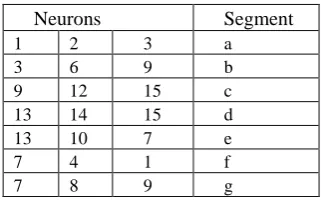
Here relationship for Neurons to segments is developed . Each segments can be recogninized with 3 Neurons.
Neurons Segment
1 2 3 a
3 6 9 b
9 12 15 c
13 14 15 d
13 10 7 e
7 4 1 f
7 8 9 g
Table 4.1: Relationship of Neurons to segments.
Here we show only result for one (“1”) digit in form of simulation result but relationship of various digits can be optimized with different segments and all the possible results have been obtained.
Digits Neurons Segments
1 3,6,9,12,15 b,c
2 1,2,3,6,7,8,9,10,13,14,15 a,b,d,e,g 3 1,2,3,6,7,8,9,12,13,14,15 a,b,c,d,g 4 1,3,4,6,7,8,9,12,15 b,c,f,g 5 1,2,3,4,7,8,9,12,13,14,15 a,c,d,f,g 6 1,2,3,4,7,8,9,10,12,13,14,15 a,c,d,e,f,g
7 1,2,3,6,9,12,15 a,b,c
IJEDR1401062
International Journal of Engineering Development and Research (www.ijedr.org)361
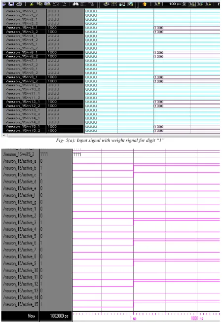
V.SIMULATIONRESULTS
Fig- 5(a): Input signal with weight signal for digit “1”
IJEDR1401062
International Journal of Engineering Development and Research (www.ijedr.org)362
Maximum combinationalpath delay
24.192ns
Number of Slices 437 out of 13312 3% Number of 4 input LUTs 774 out of 26624 2% Number of bonded IOBs 215 out of 221 97%
Table 5.1 : Device Summary
IJEDR1401062
International Journal of Engineering Development and Research (www.ijedr.org)363
VI.CONCLUSION
We describe a simplest method i.e. single layer feed-forward Neuron Network with the help of basic gates and digital circuits to build an electronic Neural Network. With Neural Network application for pattern detection from digits zero to nine can be displayed on seven segment display. Simulation result for digit one is mentioned. As shown in fig. 5(b), segments „b‟ & „c‟ are active giving logic high and rest segments are inactive giving logic low. With help of Neural Network architecture, feed forward Neuron can be designed in VHDL for particular application & technology.
REFERENCES
[1] Simon Haykin “NEURAL NETWORKS : A Comprehensive Foundation” Mc Master University
[2] Jayaram Bhasker “A VHDL Primer” American Telephone and Telegraph Company Bell Laboratories Division [3] http://www.Doc.Ic.Ac.Uk/~nd/surprise_96/journal/vol4/cs11/report.Html
[4] lecture notes: http://personal.Cityu.Edu.Hk/~meyfli/lecture/NN/index.Html
[5] S. Sai sree andal1 , N. Aravind2, Asst. Prof. 1, 2, department of ECE, teegala krishna reddy engineering College/JNTU, india, “FPGA modeling of Neuron for future Artificial intelligence applications”
[6] Andrei dinu, marcian N. Cirstea, and silvia E. Cirstea, Direct Neural-Network hardware-implementation algorithm
[7] Alexander gomperts, abhisek ukil, senior member, IEEE, and franz zurfluh, “Development and implementation of parameterized FPGA-based general purpose Neural Networks for online applications”
[8] Steven gonzalez, “Neural Networks for macroeconomic forecasting: A complementary approach to linear regression models” [9] G. P. K. Economou, E. P. Mariatos, N. M. Economopoulos, D. Lymberopoulos, and C. E. Goutis, “FPGA Implementation of
Artificial Neural Networks:An application on Medical Expert Systems”
[10] YJ Chen and WP du Plessis, “NEURAL NETWORK IMPLEMENTATION ON A FPGA”
[11] Yutaka Maeda and Toshiki Tada, “FPGA Implementation of a Pulse Density Neural Network With Learning Ability Using Simultaneous Perturbation”
[12] Marco Krips, Thomas Lammert, and Anton Kummert, “FPGA Implementation of a Neural Network for a Real-Time Hand Tracking System”
[13] S. CoriC, I. LatinoviC, A. PavasoviC “A NEURAL NETWORK FPGA IMPLEMENTATION” [14] Stephen L. Bade and Brad L. Hutchings, “FPGA-Based Stochastic Neural Networks -Implementation”
[15] Stefan Oniga, Alin Tisan, Daniel Mic, Claudiu Lung, Ioan Orha, Attila Buchman, Andrei Vida-Ratiu, “FPGA Implementation of Feed-Forward Neural
[16] Networks for Smart Devices Development”