Study of the Microstructure and Crack Evolution Behavior of
Al-5Fe-1.5Er alloy
Ming Li*, Zhiming Shi, Xiufeng Wu, Huhe Wang, Yubao Liu
College of Materials Science and Engineering, Inner Mongolia University of Technology, Hohhot 010051, PR China
Abstract: The microstructure of Al-5Fe-1.5Er alloy was characterized and analyzed by using
XRD, SEM, TEM and EDS. The effect of microstructure on the behavior of crack initiation and
propagation was investigated by in situ tensile testing. Results show that the microstructure
consists of α-Al matrix, Al3Fe, Al4Er, eutectic phase Al3Fe + Al4Er, while the 1.5 wt.% Er was
added in Al-5Fe alloy. The twin structure of the Al3Fe phase was observed, and the twin plane is
{001}. Moreover, a continuous concave and convex interface structure of the Al4Er has been
found. Al3Fe is in the form of a sheet with a clear gap inside.In situ tensile tests of the alloy at
room temperature show that the crack initiation occured mainly in the Al3Fephase, and that the
crack propagation modes include intergranular and transgranular expansion. Crack transgranular
expansion is due to the strong binding ability between Al4Er phases and surrounding organization,
and the continuous concave and convex interface structure of the Al4Er provides a significant
meshing effect on the matrix and eutectic structure.
Key words: Al-5Fe-Er alloy; microstructure; in situ tension; crack evolution
As the lightest structural material, Aluminum alloy has the advantage of low density, high
specific strength and stiffness, good thermal conductivity as well as excellent electromagnetic
shielding and anti-radiation properties, thus widely used in manufacturing, aerospace, electronic
communication and other fields[1-4]. Although 8000 series aluminum alloy is the most widely used
casting aluminum alloy in industrial production, the poor mechanical properties at room
temperature is one of its bottleneck for further application and development. Alloying effect is one
of the effective means to improve the mechanical properties of aluminum alloy. The existing
research[5-13] has shown that rare earth Er can improve the mechanical properties of aluminum
alloy . After adding rare earth Er, a stable structure of rare earth aluminum compounds can form in
the alloy, which can inhibit the precipitation of Al3Fe phase. At present, researchers have carried
* Corresponding author. Tel.: +86 15184726161, Fax.: +86 0471 6575752 E-mail address: [email protected](M. Li)
out a lot of experimental work on the improvement of microstructure and mechanical properties of
8000 series aluminum alloy after adding rare earth Er. The research findings are as follows:
Karnesky [8-14] et al found that the microstructure of 8000 series aluminum alloy was refined due
to the addition of Er (0-0.8wt.%) and formed new granular or needle like Al4Er compounds. The
study of Che, Hongmei[15-19] suggests that the Al
4Er phase precipitated at grain boundaries
increases the mechanical properties of 8000 series aluminum alloy after the addition of Er to
0.3-1.0wt.%. Tong Dorin [20-26] et al reported that the Al
4Er phase was formed in 7073 after the
addition of 1wt.% Er, and both the tensile strength and yield strength of the alloy were improved
after alloying.
At present, there are few research on the crack propagation behavior of 8000 series aluminum
alloy conducted from the perspective of in situ observation. Based on the previous experiments,
this paper adopted the in situ dynamic observation of scanning electron microscope technique to
study the crack initiation and Crack propagation behavior of Al-5Fe-1.5Er alloy at room
temperature. The paper also discussed the influence and mechanism the microstructure has on the
crack evolution.
1 Test Methods and Procedures
The pure aluminum、Al-15%Fe and Al-10%Er intermediate alloy were used as raw material
to prepare Al-5Fe-1.5Er alloy by vacuum induction melting furnace. During the smelting process,
the alloy was kept in the vacuum, protected by argon, and then shaped by metal mould casting.
The HCS-140 high frequency infrared ray carbon sulphur analyzer was employed to analyze the
composition of the alloy. By using S-3400N scanning electron microscope (SEM) and its
corresponding energy spectrometer, the microstructure and fracture appearance of the test alloy
was observed, the composition and content of the elements in each phase was analyzed. X-ray
diffraction (XRD) phase analysis was conducted by using the D/MAX-2500/PC type X-ray
diffractometer produced by Rigaku Corporation. The TEM samples of the alloy were prepared by
Gatan691 precision polishing system. The JEM2010 transmission electron microscope (TEM) and
its corollary energy dispersive spectrometer is applied in analyzing the microstructure and energy
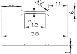
Fig. 1 Geometry and size of tensile specimen
The specimen size of in situ tensile at room temperature is shown in figure 1. After the
mechanical grinding and electrolytic polishing on the prefabricated gap of the alloy, the alloy is
put to in situ tensile test on the tensile stage under FEI Quanta 650 scanning electron microscope
(SEM)vacuum environment. The operating rate is set to 0.5mm/min.
2 Results and Discussion
2.1 XRD and SEM Results Analysis
The XRD result of test alloy is shown in figure 2a. Through PDF card analysis, the main
phase compositions are detected, including α-Al, Al3Fe,Al4Er and Al10Fe2Er.. Figure 2b is a picture
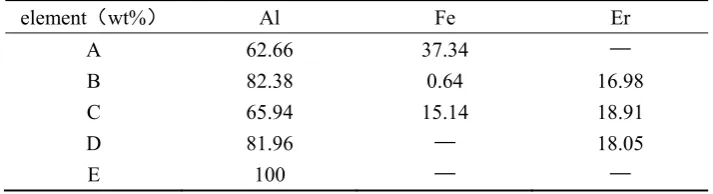
of the test alloy SEM. The EDS results analysis on the selected points is shown in table 1. It can
be seen that the morphology of the iron phase in the alloying tissue changed significantly due to
the addition of rare earth elements ,when the amount of rare earth added was 1.5 Wt. Point E is Al
matrix, and a small little amount of Fe element is dissolved in the matrix. The main alloying
elements of point B island phase contain Al, Er, Fe. Removing the influence of Fe element content,
point B is regarded as η-Al4Er phase. The particle phase at point A are mainly composed of Al ,Fe
elements, regarded as θ-Al3Fe phase. The white needle-like phase at point C are mainly composed
of Al ,Fe and Er elements. Referring to results of XRD, the phases maybe confirmed as Al10Fe2Er.
Further observation on the results of SEM alloy found that there were eutectic structure formed by
the Al4Er and its peripheral α-Al in the alloy. Moreover, part of white needle-like phase Al10Fe2Er
at grain boundaries attaches itself to η-Al4Er phase. Part of needle-like phases precipitate inwardly
20 25 30 35 40 45 50 55 60 65 70 0 400 800 1200 2500 5000 7500 10000 12500 In te ns ity( cp s) 2θ Al Al3Fe Al4Er Al10Fe2Er
(111) (200)
(220)
2b
2ɑ
Fig.2 XRD analysis (a) and SEM image (b) of the as-cast alloy Tab. 1The EDS analysis of the phases in test alloy
element(wt%) Al Fe Er
A B 62.66 82.38 37.34 0.64 — 16.98 C D E 65.94 81.96 100 15.14 — — 18.91 18.05 —
2.2 TEM Result Analysis
The Al3Fe phase is bottom center monoclinic structure, Its lattice constant is a=1.549nm、
b=0.808nm、c=1.247nm and β=107.72o。The TEM picture of the Al
3Fe phase in the test alloy and
the result of the selected area electron diffraction pattern (SAED) are shown in figure 3. Figure 3a
is the picture of the morphology of the second-phase obtaining by electrolyzation. Further
observation of the second-phase θ-Al3Fe and η-Al4Er phase in figure 3b, It can be seen that It can
be seen that θ-Al3Fe, η-Al4Er combine to grow together.. The result of the selected area electron
diffraction pattern (SAED) about θ-Al3Fe and η-Al4Er phase in figure 3b is shown in figure 3c and
figure 3d respectively. After calibration for the two sets of selected area electron diffraction
patterns, the η phase is proved to be Al4Er, with the zone axis orientation being [130](Fig. 3c) ;and
the θ phase is proved to be Al3Fe, with the zone axis orientation being (Fig. 3d) respectively.
This result further verifies the SEM and EDS results of the white needle-like phase phase is
3ɑ
3b
3c
3d
Fig. 3 TEM image of the second-phase (a) and partial enlargement map (b) and SAED pattern of the Al4Er in [130] zone axis (c) and the Al3Fe in zone axis (d)
Figure 3b indicates that a mass of plane defects penetrates the whole θ-phase grain along the
growth direction. According to the SAD pattern in Fig.3b the plane defects are considered to be
twin crystal and stacking fault[27-30]. The twin crystal appears in the (001) plane, and a mass of
stacking fault in θ-phase leads to the appearance of streaks in the SAD pattern. The HREM
morphology of the twin crystal is shown in Fig. 4a. High-density regular twinning is evident in the
θ-crystal. The HREM image shows a complex atomic arrangement, and the twinning is difficult to
distinguish, as presented in Fig. 4b. However, the adjacent atomic arrangements are slightly
different along the (001) plane after serious analysis and comparison, thereby confirming the
atomic arrangements of twinning in Fig.4b. The formation of (100) and (201) twinning may
require more energy than (001) twinning. The nucleus contains only (001) twinning and stacking
faults, and the other twinning routes are suppressed. The (110) and (110)T planes formed by (001)
twinning offers a mass of steps favoring atomic stacking along the (001) plane and leads to the
continuous growth of (001). Notably, twinning nucleation may appear and grow in the growing
4ɑ
4b
Fig.4 Highdensity twin morphology (a) and HREM image of (001) twinning of the Al3Fe phase
5ɑ
5b
5c
5d
5f
5e
FBI
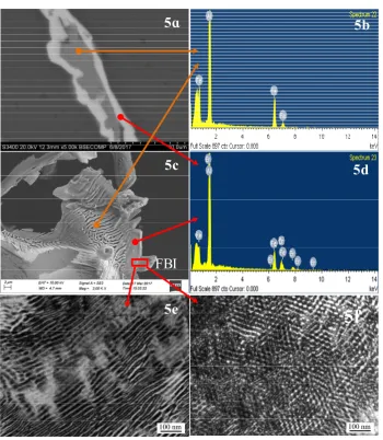
Fig. 5 The TEM images, SEM and EDS of Al4Er phase a、c. SEM image of Al4Er in grain boundary b、d. EDS analysis
e、f.TEM image of Al4Er in grain
The existence of twin structure in Al3Fe may result from the high structural stress in the alloy.
Metal casting has a relatively fast cooling rate. When the alloy is cooled to room temperature, the
structural stress in the alloy is in an unbalanced state and has a tendency to release spontaneously.
induced to form.
η-Al4Er phase is an cubic structure, and its lattice constant is (a=0.4215nm, , α=β=γ=90°).
Figure 5 shows the TEM、EDS and SEM result of Al4 Er phase. Figure 5a is a picture of needle
phase SEM at grain boundary. According to the result of needle-like phase EDS in figure 5b and
figure 5d, the proportion of Al and Er element contents in the outer edge of phase is relatively
large. The calibration of the selected area electron diffraction pattern (SAED) on the needle-like
phase prove it to be Al4Erphase, with [130] being the zone axis orientation (Fig.3c) , which is
consistent with the result of needle-like SEM and EDS. Further investigation revealed that the
grain boundaries of the needle-like Al4Er phase is coated on the outside side of Al3Fe.We came to
the conclusion that Al10Fe2Er is a composite phase, the outer layer is Al4Er, and the inner layer is
Al3Fe , which can be identified as θ-Al3Fe/ η-Al4Er.The end face of the needle-like Al4Er is
parallel with the bonding interface of α-Al matrix along the length direction, and is intermittent
along the width direction exhibiting an obvious concave convex appearance. At this moment,
Al4Er starts the adsorption growth along the width direction, namely, along the width direction, all
the atoms on the concave convex interface will combined into the crystal, thus the crystal, even in
a small undercooling, can grow up quickly. However, the uneven degree of diffusion of Al and Er
atoms on the concave convex interface of Al4Erfront edge result in the formation of wall-like
Al4Er. The change in the interfacial morphology of Al4Erreflects the needle-like Al4Er phase tends
to grow into short rod-like shapes. Figure 5c is the SEM image of the needle-like phase Al4Er and
Al3Fe inside the grain. It can be seen that two phases grow perpendicular to each other,so the
dense Al4Er phase hinders the diffusion of iron and inhibits the growth of Al3Fe. The shape of
smooth edge needle-like Al4Er phase is in good agreement with Al matrix. The η- Al4Er exhibits
evident fibrous characteristics, as observed from two zone axes under TEM presented in Figs. 5e
and 5f.The average distance of fibers is approximately 20nm. The η-phase should be disordered
during the generation process of alloy phase because of attached growth . The η- Al4Er is the
dominant reaction product and performs an important role to control the the generation process of
alloy phase in molten aluminum. In addition, the finger-like morphology of the η- Al4Er was
attributed to the distinctive crystal structure; the orthorhombic structure consists of 30% vacancies
along the c-axis [001], which offers a rapid diffusion path. However, a η-phase attached growth
are offered, there were many dislocation line inside of the Al4Er phase and the phase is proved to
be brittle phase.
2.3 The Results Analysis of In Situ Tensile Test at Room Temperature
The process of the alloy in situ tensile at room temperature is shown in figure 6. Figure 6a
shows the relation curve between the load and displacement curves of the alloy specimens. The in
situ tension process observation starts from the position of the arrow in the diagram. The tensile
scan images of the different corresponding positions are shown in figure 6 (b-o). Figure 6b is the
back-scattered electron scanning images of the specimen when the external load reaches 200N. At
the moment, the specimen is in the elastic deformation stage, and for the position of the sample
reserved gap front, no crack source has formatted. When the load keeps to increase (Figure 6c),
micro crack source began to form in the gaps of the specimen due to stress concentration. No
significant change is found in the middle part of the specimen. A close magnification of the
selected area in figure 6c(Figure 6d) clearly shows that a large number of second phases, i.e.
needle-like θ-Al3Fe+η-Al4Er, particle Al3Fe phase, island-like Al4Er dispersively distributed in the
α-Al matrix of alloy specimen. Moreover, the microstructure of the alloy is dense. Select the
elliptic region A and B (divorced eutectic Al3Fe+ Al4Er phase) in figure d as a comparative
observation area. Continue to increase the external load (Fig. 6e), the cracks of the gap grows. Due
to the effect of stress concentration, some Al3Fe phase at the front of the crack source (the
magnified area in figure 6e) and in the middle of the specimen begin to generate fine cracks. For
the time being, no obvious plastic deformation characteristics was observed in the central picture
of the specimen (figure 6f, a selected area from figure 6e), and no microcrack formation is found
in aluminum compounds. Continue to increase the external force, the main crack expanded rapidly
(figure 6g). There were an obvious slip bands and secondary cracks on both sides of the main
crack. The formation of secondary cracks is a result of the further expansion of the micro cracks in
Al3Fe/Al4Er phase. Enlarge the selected areas in figure 6g(figure 6h), one can see the widen micro
cracks formed by the broken island-like phase Al4Er on both sides of the main crack. The
needle-like phase Al3Fe/Al4Er and granular Al3Fe phase are broken. Al3Fe/Al4Er cracked several
times along the length direction. The width of micro cracks formed by the broken rare earth
aluminide rupture is relatively small, and the bonding between the rare earth aluminum
Al3Fe/Al4Er phase and particle Al4Er phase in the alloy can effectively resist the external load
changes. In addition, the movement of the slip line is hindered by the rare earth aluminide, which
further improves the tensile strength of the alloy. With the tension continues, the front part of the
main crack front showed a "Z" - shaped expansion (see from the selected area in the figure 6i in
the selected block area) and next to the front of the main crack, an obvious plastic deformation
region (slip band formation) appeared in the matrix. When the main crack expanded to the area,
the crack path extended forward along the slip plane (steps), thus forming the front end of "Z"
shape crack. This kind of winding crack propagation can improve the fatigue strength of alloy [12].
The Z shaped crack continues to expand forward. When the crack passed grain 1 and grain 2, one
can see from the path of the main crack that there are two forms of crack expansion, i.e.
transgranular and intergranular. The micro cracks that near the main crack grain are connected to
each other, expanding a pathway for its extension. When the main crack expand to the grains 3, it
didn’t extends forward along the grain boundary but the transgranular went through the grain
interior instability region (see the area surrounded by the blue curve in figure 6j). The red arrow in
the diagram points to the direction of crack propagation. the particle Al3Fe phase in the coarse θ+η
eutectic structure at the grain boundary (the area selected by yellow lines) is broken. And the weak
bonding ability between the eutectic structure and the matrix interface led to cracks and separation
of the two. Further observation revealed that formation of the needle-like phase Al3Fe/Al4Er and
particle Al4Er phase formed at the grain boundary made eutectic structure and matrix connected
closely together, especially the concave and convex interface structure of Al4Er increases its
meshing area with the surrounding tissue, which further hindered the separation between the
primary crystal α-Al and Al element in the eutectic structure. The step is to block the Al from the
αAl and the eutectic structure. Therefore, the interface needs to provide a larger external load to
initiate and propagate cracks, which results in transgranular cracking of the main crack. Continue
to increase the external force, the stress concentration area exists in front of the main crack,
making the surface of the sample unstable (the selected region C and D in figure 6k). There are
slip bands of different orientation in the region.Further observation on the fracture behavior of
crack through the selected region C and D (figure 6m and figure n) found that in figure 6m, each
piece of Al3Fe/Al4Er and matrix interface bond closely and slides along the direction of
Al3Fe/Al4Erand the matrix interface has hindered the slip of the matrix, forcing the need-like
phase break into several segments of almost the same length(about 2μm)along the length
direction.
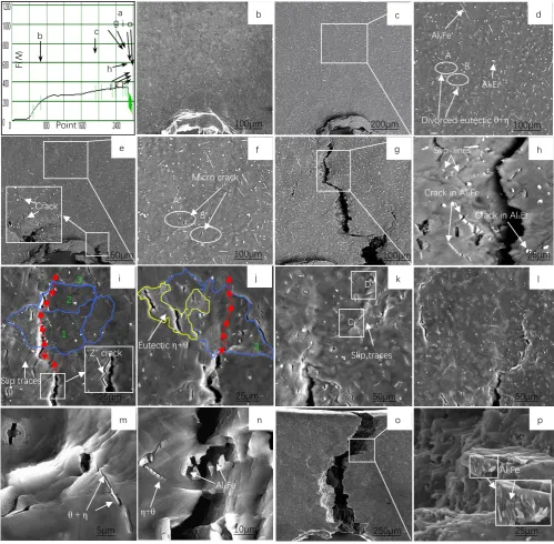
Fig. 6 The in situ tension test of the alloy at room temperature
(a) Load-position curve; (b) SEM image of the position b in fig.a ;(c) SEM of the position c in fig.a ; (d) the enlarge image of selected area in fig. c; (e) SEM image at F=340N; (f) the enlarge image of selected area in fig. e; (g) (h) (i) (j) (k) (l) SEM images of the position g, h, i, j, k, l in fig.a; (m) the enlarge image of selected area C in fig. k; (n) the enlarge image of selected area D in fig. k; (o)SEM image of fractured specimen; (p) the enlarge image of selected area in fig. o
D
C
Slip traces
Slip traces
“Z” crack Eutectic η+θ
Al3Fe
θ + η η+θ
Al3Fe
Al3Fe
Al4Er
Divorced eutectic θ+η A
B
Micro crack
A’ B’
Crack in Al3Fe
Crack in Al4Er
Slip-lines Crack F( N ) Point
b c
i o g
h
j k l
a b c d
e f g h
i j k l
m n o p
100μm 200μm 100μm
150μm 100μm 100μm 25μm
25μm 25μm 50μm 50μm
5μm 10μm 250μm 25μm
1 2
3
The fracture is mainly caused by the stress concentration that the convex and concave
interface of Al4Er bore, the force of which is stronger than the bond strength between the
Al3Fe/Al4Er eutectic structure and the matrix. The crack in figure 6n to continue to move forward
and go through the unstable region, making the brittle hardness phase Al3Fe break and separate.
Increase the tensile strength and the alloy specimen fractures quickly. The surface of specimen
fracture (figure 6o) along the crack direction is non-homogeneous. Further observation of the
selected region in the fracture (figure 6p) found the black hole at the bottom right should be
caused by the fractured phase Al3Fe. The nearby residual of Al3Fe is exposed in the above the
surface of the fracture matrix on the right side of the main crack, and fractures along the direction
of the stress, which shows that the main crack produced a secondary micro cracks going through
the large size Al3Fe. Under the external force, the secondary micro cracks extend to the nearby
Al3Fe phase, releasing the stress concentration produced by Al3Fe and the surrounding matrix.
The micro cracks continue to propagate to the matrix. Under the effect of sheer stress, the matrix
form into slippage step and converges to form dimples at the edge of the matrix slippage step
through the extension of micro cracks of Al3Fe2, whereas, the effect of cross-slip will lead to the
formation of a tear ridge at the fracture surface.
δ
δ
δ
δ
Al3Fe
δ δ
Al3Fe
α Al
7ɑ
cracking
α Al
Al4Er
Al3Fe
Al3Fe/Al4Er 7b
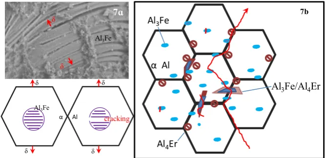
Fig.7 Schematic diagram of crack propagation in the Al3Fe(a) and in the alloy(b)
Figure 7 is a schematic diagram of the crack propagation path. Since the Al3Fe at the grain
boundary can easily initiate micro cracks, theAl3Fe/Al4Er eutectic structure breaks when the main
crack passes. The bonding ability between Al3Fe and matrix interface is weak, thus causing
detachment of the two, making the cracks extend along the grain boundaries. When the rare earth
aluminide is precipitated from the eutectic structure at grain boundaries, the compounds have a
mechanical stability of the eutectic structure at grain boundaries, resulting in the formation of
unstable region inside the grains, and casing the expansion of the transgranular crack.
Secondary crack Tear ridges
Al3Fe
+1
8ɑ
8b
Fig. 8 SEM image (a) and EDS analysis (b) of the alloy
The analysis on EDS test results of the selected point from the fracture surface (figure 8b)
found that the point includes Al, Fe and Er, indicating it is on the grain boundary. Therefore, the
fracture mode of the alloy is a combination of intergranular fracture and quasi cleavage fracture.
3 Conclusions
(1) The main phase composition of Al-5Fe-1.5Er alloy includes α-Al matrix, Al4Er, eutectic phase
Al10Fe2Er ; Al3Fe phase.is needle-like and particle. There is a twin structure in Al3Fe, with the
twin plane being {001}. Al4Er has a concave and convex interface structure. Al10Fe2Er is a
composite phase, the outer layer is Al4Er, and the inner layer is Al3Fe , named as θ-Al3Fe/ η-Al4Er
(2) In situ tensile test at room temperature shows that the crack are mainly formed inside the
coarse particle Al3Fe and mode of crack propagation include the crack growth mode includes
intergranular expansion and intergranular propagation. Intergranular propagation is the result of
the strong binding ability between the phase distributed along the grain boundaries, Al4Er, and the
surrounding interface. The pinning effect is remarkable. The concave and convex interface
structure of the Al4Erhas a strong meshing effect on the eutectic structure and the matrix, which
improves the mechanical stability between the eutectic structure at grain boundaries and the
interface of the matrix.
Acknowledgments
The authors gratefully acknowledge financial support from the National Natural Science
References
[1]Wang, X., Guan, RG. & Wang, Y. Metall and Materi Trans B. 49 (2018) 2225–2231. [2] Moustafa, M.A..J. Mater. Proc. Technol. 209(2009) 605–610.
[3]Çadirli, E., Tecer, H., Sahin, M., Yilmaz, E., Kirindi, T Gündüz, M.J.Alloys Compd., 632(2015) 229–237.
[4]Booth-Morrison, C., Seidman, D. N., Dunand, D.C..Acta Mater.. 60(2012)3643–3654. [5]Belov, N.A., Korotkova, N.O., Alabin, A.N. Russ. J. Non-ferrous Metals. 59 (2018)276–283 [6] Q.R. Zhao, Z. Qian, X.L. Cui, Y.Y. Wu, and X.F. Liu:J. Alloys Compd., 650(2015) 768–776. [7 ] R.G.Guan,Y.F.Shen,Z.Y.Zhao,X.. J. Mater. Sci. Technol.33(2016) 215-223.
[8]Karnesky, Richard A.; Dunand, David C.; Seidman, David N. ACTA MATER.. 57(2009) 4022-4031
[9] S. Miyazakia, A. Kawachib, S. Kumaia, A. Satoa.Mater. Sci. Eng. A, 400–401 (2005) 294-299. [10]J.M.Cubero-Sesin,Z..Metall. Mater. Trans. A,43(2012)5182-5192.
[11]S.S. Nayak, B.S. Murty, S.K. Pabi. Bull. Mater. Sci., 31 (2008) 449-454.
[12] Seidman, David N.Karnesky, Richard A.; Dunand, David C. Acat Mater. 57(2009) 4022-4031.
[13] R.A. Mesquita, D.R. Leiva, A.R. Yavari, W.J. Botta Filho.Mater. Sci. Eng., A, 453 (2007), pp. 161-169.
[14 ] E.A. Starke, J.T. Staley.Prog. Aero. Sci., 32 (1996)131-172.
[15] Che, Hongmei; Jiang, Xianquan; Qiao, Nan; et. al.. J. Alloys Compd.., 708(2017),P P: 662-670.
[16] Feng, J; Huang, WD; Lin, X. J Crys G. 197(1999)393-398.
[17] Goulart, Pedro R.; Cruz, Kleber S.; Spinelli, Jose E. J. Alloys Compd..470(2009) 589-599. [18 ] TRIVEDI, R; KURZ, W . Int Mater Rev.39(1994) 49-74.
[19 ] P.R. Goulart, K.S. Cruz, J.E. Spinelli, I.L. Ferreira, N. Cheung, J. Alloy. Compd., 470 (2009) 589-599
[20 ] T. Dorin, N. Stanford, N. Birbilis, R.K. Gupta. Sci., 100 (2015) 396-403. [21 ] Wen, S. P.; Gao, K. Y.; Huang, H.; J. Alloys Compd.574(2013)92-97. [22 ] Zhang, Y; Gao, K. Y; Wen, S. P; J. Alloys Compd. 610(2014) 27-34. [23 ] Fuller, CB; Seidman, DN; Dunand, DC .Acta Mater.. 51(2003) 4803-4814 [24 ] Y. Harada, D.C. Dunand.Intermetallics, 17 (2009) 17-24.
[25]A.M.Samuel,G.H.Garza-Elizondo,H.W.Doty,F.H.Samuel.Mater. Des..80(2015)99-108 [26 ] U. Prakash, G. Sauthoff. Intermetallics, 9 (2001) 107-112.
[27 ] H. Sasaki, K. Kita, J. Nagahora, A. Inoue.Mater. Trans., 42 (2001)1561-1565 [28 ] FREIBURG, C; GRUSHKO, B. J. Alloys Compd.210(1994) 149-152
![Fig. 3 TEM image of the second-phase (a) and partial enlargement map (b) and SAED pattern of the Al4Er in [130]](https://thumb-us.123doks.com/thumbv2/123dok_us/8007774.1330782/5.595.111.477.76.411/fig-image-second-phase-partial-enlargement-saed-pattern.webp)