IJEDR1502102
International Journal of Engineering Development and Research (www.ijedr.org)556
Analytical Analysis for Enhancement of Performance
and Efficiency for Different Blade of HAWT by
Computer Program
1
Hemant Rav Patel, 2Dr. V.N. Bartaria, 3Dr. A.S. Rathore
1Department of Mechanical Engineering, LNCT, Bhopal (MP) 2Professor, Department of Mechanical Engineering, LNCT, Bhopal (MP)
3Professor, Department of Mechanical Engineering, BERI, Bhopal (MP)
________________________________________________________________________________________________________
Abstract - In view of the requirements to access the wind energy efficiently, a model of three bladed horizontal axis wind turbine is to develop for its aerodynamic efficiency by considering an idealized wind turbine rotor. This study introduces important concepts and illustrates the general behaviour of wind turbine rotors and the airflow around wind turbine rotors. The analysis is also used to determine theoretical performance limits for wind turbines. This study includes increase the power coefficient of horizontal axis wind turbine, to carry out performance analysis and power prediction of horizontal axis wind turbine, Comparison of power prediction with an existing turbine.
Keywords - Aerodynamics, BEM Theory, Blade Profile, Performance prediction method.
________________________________________________________________________________________________________
I.INTRODUCTION
About 70% of India's energy generation capacity is from fossil fuels with coal accounting for 40% of India's total energy consumption followed by crude oil and natural gas at 24% and 6% respectively. India is largely dependent on fossil fuel imports to meet its energy demands by 2030; India's dependence on energy imports is expected to exceed 53% of the country's total energy consumption. In 2009-10, the country imported 159.26 million tonnes of crude oil which amount to 80% of its domestic crude oil consumption and 31% of the country's total imports are oil imports. The growth of electricity generation in India has been hindered by domestic coal shortages and as a consequence, India's coal imports for electricity generation increased by 18% in 2010.
Wind energy is one of the most cost effective of all types of renewable energy. The wind velocity varies on a daily and hourly basis, the maximum amount of power produced by a wind turbine at a given time cannot be controlled by the operator. This lead s to a different criterion for optimum design than that used for other equipment where the rate of electricity production can be controlled up to the equipment maximum rating. However, to make wind a viable source of energy electricity in particular careful design of wind-capturing machines is necessary. A variety of theories are used to create wind turbines that can efficiently capture energy from the wind.
Power in the wind
The kinetic energy of wind flow is applied on the wind turbines. Due to this rotors of turbine reduce the wind velocity from the undisturbed wind speed far in front of the rotor to a reduced air stream velocity behind the rotor. The velocity difference of wind velocity is a measure for the extracted kinetic energy which turns the rotor connected to the electrical generator.
The total power of a wind stream is equal to the rate of the incoming kinetic energy of the stream,
2
2
V
m
P
- - - 1.1Where;
P = total power, W
m
= mass flow rate, kg/s V = incoming wind velocity, m/sThe mass flow rate is given by the continuity equation
AV
m
- - - 1.2
= wind density, kg/m3A= cross-section area of stream, m3 Then equation 1 becomes
3
2
1
AV
P
- - - 1.3IJEDR1502102
International Journal of Engineering Development and Research (www.ijedr.org)557
II.METHODOLOGY
Blade Element-Momentum Theory
Blade Element Momentum Theory of depending on the axial and tangential induction factors by equating the torque and force relations derived from each blade element and momentum theories [1]. In the Theory of momentum, the model of flow around a wind turbine can be express by actuator disc. The theory use is homogeneous, steady, uniform, incompressible flow; wake is use for Basic assumptions is assumed non-rotating and turbulence effects are assumed unimportant. Across the section the total mass flow rate per unit time is also assumed to be constant [2].
Corrections used in BEM Theory
Blade Element Momentum Theory is a simple theory which is based on some small assumptions. To compensate for certain inaccuracies some corrections are usually applied. These corrections are the tip loss corrections and turbulent wake correction. Basically, when the turbulence effects become strong, induction factors are evaluated with a modified formula. In addition, Prantl’s tip loss model is applied on the blade for to the loading distribution for the tip loss correction [2].
Prandtltip-loss factor is given by the following equation [2.4, 2.5]
[ [
( )
]
] - - - 2.1
In the theory of Blade Element, we divide the blade into several elements and in each element it is assumed that the performance of the overall blade can be derived from the 2D airfoil which is used at that section by integrating it throughout the blade. Using the induction factor definitions, conservation of angular momentum and conservation of linear momentum equations are derived from blade element and momentum theories separately. The detailed derivations and explanations may be found in [3, 5]. Hence, in the theory of Blade Element Momentum (BEM), a, a′ and σ are given by:
- - - - - - 2.2
* * ++ ⁄
** + + ⁄
To find out the maximum power coefficient for a selected airfoil type, dividing the blade length into n-elements, the speed ratio of local tip for each blade element can then be calculated with the use of following equation [2.5]:
Local Tip Speed Ratio
- - - 2.5
Optimum Relative wind for each blade element
(
)
⁄ [ √ ] - - - 2.7 Tip loss factor for each blade element
[
⁄ ( ⁄ )
] - - - - - 2.8
Twist distribution:
- - - -2.9
Chord length distribution:
- - - 2.10 Power coefficient:
∑ ( ) ( )( ) [
]
- - - 2.11
III.AIRFOIL DATABASE
IJEDR1502102
International Journal of Engineering Development and Research (www.ijedr.org)558
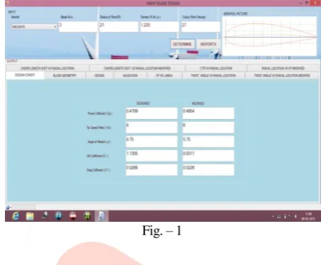
airfoil database consists of many airfoils or airfoil families designed for wind turbines or used in wind turbine applications [6, 7 and 8].In the database, lift and drag coefficients for a range of angle of attack values and at low Reynolds numbers are used. One property of this database is that the only force coefficients produced in wind tunnel tests are used for each airfoil. The main goal of this criterion is to perform BEM theory analysis more accurately. By keeping 2D section data accuracy of a wind turbine blade as close to real as possible, wind turbine performances are predicted as accurate as possible.
The application of the BEM method with this concept is shown during the validation of BEM analysis. Main properties of airfoils used in the database. Eleven airfoil found in the literature is used in the database.
Fig. – 1
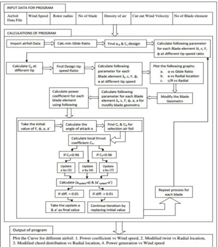
IV.COMPUTER PROGRAM:
IJEDR1502102
International Journal of Engineering Development and Research (www.ijedr.org)556
Fig. - 2V.RESULTS
1. Variation of power coefficient with tip speed ratio (Cp vs )
Fig.-3 0
0.1 0.2 0.3 0.4 0.5 0.6
1 3 5 7 9 11 13
IJEDR1502102
International Journal of Engineering Development and Research (www.ijedr.org)557
Power coefficient increases accordingly as tip speed ratio increases but as certain limit excides it goes on decreasing for all the airfoil. Tip speed ratio at which power coefficient is maximum is called design tip speed ratio.2. Variation of twist angle with radial location ( vs r/R)
Fig.-4
There is decrease in twisting angle from root to tip and negative nearby tip-section. 3. Variation of modified chord distribution with radial location (c/R vs r/R)
Fig.-5
Chord has modified for enhancing the aerodynamic property of blade and makes the chord distribution linear. 4. Variation of modified twist angle with radial location (modified vs r/R)
Fig.-6
This modification has been executed so that twist allocation of the modified blade has been linearized. Also at some distance from blade root the twist becomes negative which commonly causes the blade elements from this distance to blade tip to be stalled. To prevent these blade elements from being in stall region, their twist values are set to zero.
IJEDR1502102
International Journal of Engineering Development and Research (www.ijedr.org)558
Fig.-7Along with wind speed power also increases and maximum at nominal wind velocity 14 m/sec and maximum power generated by S-8052 airfoil.
VI.CONCLUSION
In this paper a computer program has been used for investigation of aerodynamics of various airfoils. We have take the 12 airfoils data for 21 m length of blade out of which S-8052 airfoil has created maximum power at nominal wind speed. This program can be used for any number of airfoils.
VII.NOMENCLATURE
CP: power coefficient of wind turbine rotor
CPmax: maximum rotor power coefficient
CT: thrust coefficient of wind turbine rotor
P: power output from wind turbine rotor ṁ: air mass flow rate through rotor plane U∞: free stream velocity of wind
Urel: relative wind velocity
UR: uniform wind velocity at rotor plane
A: area of wind turbine rotor R: radius of wind turbine rotor r: radial coordinate at rotor plane r i: blade radius for the ith blade element
T: rotor thrust Q: rotor torque
C D: drag coefficient of an airfoil
C L: lift coefficient of an airfoil
F: tip-loss factor
F i: tip-loss factor for the i th
blade element N: number of blade elements
B: number of blades of a rotor a: axial induction factor at rotor plane a′: angular induction factor
λ: tip-speed ratio of rotor λ d: design tip-speed ratio
λ r : local tip-speed ratio
λ r,i: local tip-speed ratio for the i th
blade element c: blade chord length
ci: blade chord length for the ith blade element
ρ: air density α: angle of attack
α design: design angle of attack
θ: pitch angle (blade setting angle) θ i: pitch angle for the ith blade element
ϕ opt: optimum relative wind angle
σ: solidity ratio
ν: kinematic viscosity of air γ: glide ratio
Re: Reynolds number
HAWT : horizontal-axis wind turbine BEM: blade element-momentum
0 200 400 600 800 1000 1200
1 4 7 101316192225
IJEDR1502102
International Journal of Engineering Development and Research (www.ijedr.org)559
TSR: Tip-Speed RatioVIII.REFERENCE
[1] Ali Vardar, Ilknur Alibas, “Research on wind turbine rotor models using NACA profiles”; Renewable Energy 33 (2008) 1721–1732
[2] A.S. Rathore & S. Ahmed “Aerodynamic analyses of horizontal axis wind turbine by different blade airfoil using computer program” iosr journal of engineering, vol. 2, Jan 2012
[3] Manwell, J. F., McGowan, J. G., Rogers, A. L., “Wind Energy Explained; Theory, Design and Application”, John Wiley & Sons Ltd, 2002
[4] J. F. Manwell, J. G. McGowan, A. L. Rogers Wing Energy, Theory, Design and Applications, Contract NAS2-11665, Muadyne Report 83-2-3, John Wiley and Sons, 2006.
[5] Spera, D. A., “Wind Turbine Technology”, ASME Press, 1998
[6] Gundtoft S. Design of an optimal rotor i.e. pitch angle and chord length of the blades and how to calculate the power production. University College of Aarhus June 2009.