IJEDR1402047
International Journal of Engineering Development and Research (www.ijedr.org)1563
Speed and Torque Ripple Reduction of the Brushless
DC Motor using Voltage and Current Controller
1
Firdaus F. Belim,
2Bharti B. Parmar,
3Devang Parmar
1P.G. Student (Electrical Power System), 2Senior Lecturer, 3Assistant Professor Electrical Engineering Department,
V. V. P. Engineering College, Rajkot, India.
1[email protected], 2[email protected], 3[email protected]
________________________________________________________________________________________________________
Abstract -The main objective of this paper is to build a simple current and voltage controlled modulation techniques with filters for brushless dc motors using PSIM software. A wide range of torque and speed control of the electric motor is required in most applications. Because of fast response, low inertia, high reliability and maintenance free advantages of brushless dc motors, it is used in applications which required wide range of speed and torque control. The conventional dc machine fulfills these requirements, but the disadvantage of conventional dc machine is it requires constant maintenance. Brushless dc motor required less maintenance because permanent magnet is used so they do not have brushes. Under ideal condition with trapezoidal back emf the torque produced by the brushless dc motors is constant. However in practice the torque ripple appears on the delivered output toque. In armature current the harmonics is produce because of brushless dc motors uses power electronic switches for the commutation purpose. In this paper voltage and current controllers are used to reduce speed and torque ripples.
Index Terms -BLDC Motor, PSIM, Voltage source inverter (VSI), Total Harmonic Distortion (THD), FFT analysis
________________________________________________________________________________________________________
I.INTRODUCTION
In recent year brushless dc motors are widely used in industries such as Aerospace, Vehicle Tracking, Aircraft on board instrumentation, Fuel monitoring System, Appliances, Automotive, Consumer, Medical, and Industrial Automation Equipment because of their advantages like high efficiency, reliability, high starting torque, lower maintenance compared to its conventional brushed dc motor. Electronic commutation is used in brushless dc motor instead of commutation the armature current using brushes. Brushless dc motors are available in many different power ratings, from very small motors as used in hard disk drives to large motors in electric vehicles.
However in practical brushless drive, significant torque pulsations may arise due to the back emf waveform departing from the ideal as well as commutation torque ripple, pulse width modulation (PWM) switching. Torque ripple due to the current commutation is caused by the mismatches between the applied electromotive force and the phase currents with the motor electrical dynamics. These torque ripples produces noise and degrade speed-control characteristics especially at low speed [2].
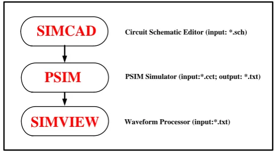
The simulation process of PSIM is shown in Fig. 1. This simulation package of PSIM is a simulation package specifically designed for motor control and power electronics which is consists of the circuit schematic program PSIM, the simulator engine, and the waveform processing program SIMVIEW [7].
SIMCAD
PSIM
SIMVIEW
Waveform Processor (input:*.txt) PSIM Simulator (input:*.cct; output: *.txt) Circuit Schematic Editor (input: *.sch)IJEDR1402047
International Journal of Engineering Development and Research (www.ijedr.org)1564
II.VOLTAGE CONTROLLER
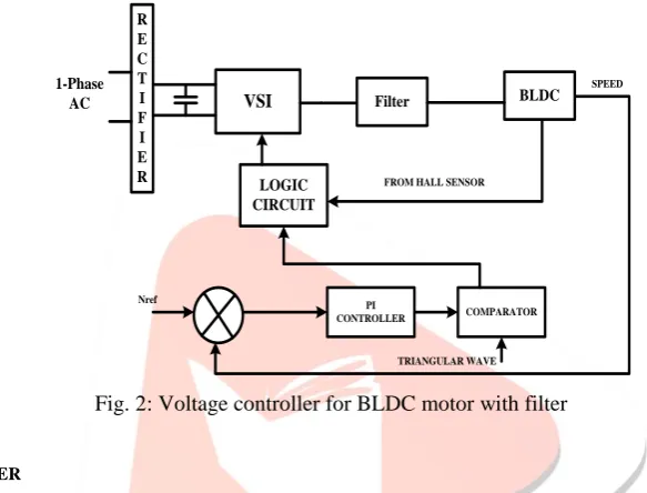
For the operation of BLDC motor it requires a power electronic drive circuit and a commutation system. The Fig. 2 describes the functional units present in the drive circuit and the associated commutation controller for the BLDC motor.
A 4-pole BLDC motor is driven by the inverter for 1200 commutation. The rotor position can be sensed by a hall-effect sensor, providing three square wave signals with phase shift of 1200. These signals are decoded to provide the firing signals for 1200 conduction on each of the three phases by a combinational logic. To minimize the high frequency switching voltage ripple component the filter circuit is provided, which filter out the inverter voltage for the motor.
The LC filter for the proposed work is connected in the interface of the drive and the motor. In this system the LC filter acts as a low pass filtering circuit, it offers high impedance for high frequency component of the voltage and very minimum impedance to the power frequency voltage components and thereby harmonics in the supply voltage to the motor are minimize. The series inductance reduces the torque ripples because it opposes the sudden changes in the current due to electronic commutation [1]. R E C T I F I E R VSI LOGIC CIRCUIT PI CONTROLLER COMPARATOR 1-Phase AC SPEED
FROM HALL SENSOR
TRIANGULAR WAVE Nref
BLDC Filter
Fig. 2: Voltage controller for BLDC motor with filter
III.CURRENT CONTROLLER
The drive system consists of a dc power supply, three-phase inverter, a BLDC permanent magnet motor and LC filter. The high frequency switching voltage ripple component in inverter voltage of motor is filter out using filter circuit. The inductor- capacitor filter for the proposed work is connected as shown in Fig. 3 which is in the interface of the drive and the motor. In this system the LC filter acts as a low pass filtering circuit, it offers high impedance for high frequency component of the voltage and very minimum impedance to the power frequency voltage components and thereby harmonics in the supply voltage to the motor are minimize. The series inductance reduces the torque ripples because it opposes the sudden changes in the current due to electronic commutation.
Position Sensor System and Current Sensor System are mainly two parts of sensing system. Position Sensor System is based on three Hall Effect cells placed inside the motor, and current sensor system is based on the current sensors. The current sensors in three phase brushless dc motor are to be placed in any two phases. Because of the following reasons there is no requirement of measurement the currents in the three phases: 1) there is no neutral connection, and hence the third phase current can be obtained from the other two. 2) The sensing of the current is only required to get the value of the magnitude (the phase-shift and sequence is given by the position sensor) [3].
DC SUPPLY 3-PHASE
INVERTER FILTER 3-PHASE BLDC MOTOR POSITION SENSOR CONTROLLER RECTIFIER CURRENT SENSOR GATE DRIVE
IJEDR1402047
International Journal of Engineering Development and Research (www.ijedr.org)1565
The control circuit of current controller for BLDC motor with filter shown in Fig. 3 has sub blocks of analog and digital electronic circuits (comparators, PI controller and adder devices). From the signal rectification of the phase currents the dc signal is obtained and this signal rectification uses germanium diodes which is used to reduce the problem of nonlinearity introduced by the fixed voltage drop of the diodes used in the rectifier.IV.CURRENT CONTROLLER DESIGN
PI controller is used in current controller design because of the main advantage of using PI controller is it has Zero steady error. Using a Hall Effect sensor, slotted optical disk or some other transducer the rotor shaft position is sense, providing signals as represented. The signals are decoded to provide the firing signals for 120°conduction on each of the three phases by combinational logic [4]. The upper and lower phase lag transistors are control using six outputs of the commutation logic or rotor position decoder.
PI
+
-+
-Idc IerrTriangular Carrier
Comparator
PWM Pulse Iref
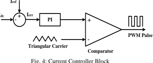
Fig. 4: Current Controller Block
Figure 4 shows the basic block diagram of current controller. The Iref is compare with Idc which is generates error signal Ierr. This error is then passed through a PI controller, and output of this PI controller is compare with triangular carrier which generate PWM signal.
Using constant DC signal, current control of BLDC motor can be done [5]. Hysteresis-type regulator which maintains the current within adjustable limits is used to regulate instantaneous current in each phase of brushless dc motor. This is called „current mode‟ control and to control the switching there are several algorithms are possible. Sensors are needed in each phase in this case and the bandwidth of this sensor is must be wider than that of the sensing resistor. The Techo-generator TG is used to derive speed feedback signal, can be derived from the shaft position sensor by a frequency to voltage converter. In high performance systems resolver or optical encoder is used as shaft position sensor, with special purpose decoding circuitry. To improve various aspects of performance such as dynamic performance or speed range and efficiency this level of control as a function of speed and load are used.
V.FILTER DESIGN
Major role in the performance of the drive is selection of LC component present in the filter. The quality of the voltage given to the motor is improves using charging and discharging of the capacitor. Both L-filter and C-filter‟s advantages are possessed in this filter. Ripple factor in L-filter or C-filter is higher than obtained by L-C filter for the same values of L and C [1].
L
C
L- Load
R- Load
Fig.5: Equivalent LC filter for one phase
L-C filter is used for reducing the ripple from the output voltage. Fig. 5 shows the equivalent circuit of L-C filter. The inductor current rating should be equal to the current ratings of the motor. The value of filter capacitor C can be calculated by
√ ( ) ( )
Where,
R = load resistance LL = the load inductance
IJEDR1402047
International Journal of Engineering Development and Research (www.ijedr.org)1566
√ [
( ) ] ( )
VRF is voltage ripple factor. we are taking VRF as 0.01 because according to IEEE standard maximum allowable range to ripples is up to 10%, and calculating L using C as already obtained.
VI.SIMULATION RESULTS
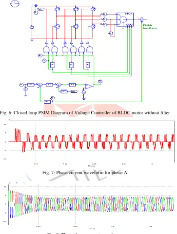
A. Voltage Controller without Filters
Fig. 6: Closed loop PSIM Diagram of Voltage Controller of BLDC motor without filter
Fig. 7: Phase current waveform for phase A
Fig. 8: Three phase current waveforms
IJEDR1402047
International Journal of Engineering Development and Research (www.ijedr.org)1567
Fig. 10: Electromagnetic torque waveform of BLDC motorFig. 11 FFT analysis of phase A current (THD = 72.61%)
Fig. 12 FFT analysis of line voltage (THD = 53.70%)
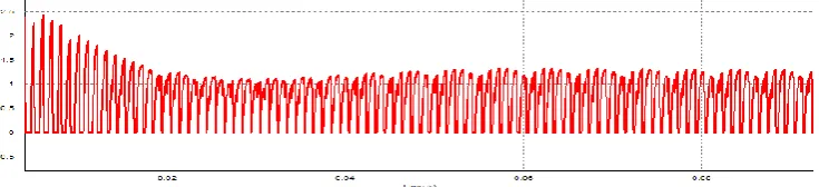
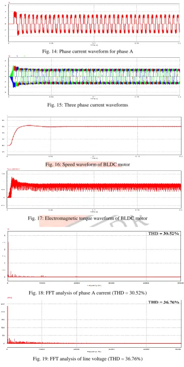
B. Voltage Controller with Filters
IJEDR1402047
International Journal of Engineering Development and Research (www.ijedr.org)1568
Fig. 14: Phase current waveform for phase AFig. 15: Three phase current waveforms
Fig. 16: Speed waveform of BLDC motor
Fig. 17: Electromagnetic torque waveform of BLDC motor
Fig. 18: FFT analysis of phase A current (THD = 30.52%)
IJEDR1402047
International Journal of Engineering Development and Research (www.ijedr.org)1569
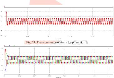
C. Current Controller without Filters
Fig. 20: Closed loop PSIM Diagram of Current Controller of BLDC motor without filters
Fig. 21: Phase current waveform for phase A
Fig. 22: Three Phase current waveforms
IJEDR1402047
International Journal of Engineering Development and Research (www.ijedr.org)1570
Fig. 24: Electromagnetic torque waveform of BLDC motorFig. 25: FFT analysis of phase A current (30.25%)
Fig. 26: FFT analysis of line voltage (THD = 32.62%)
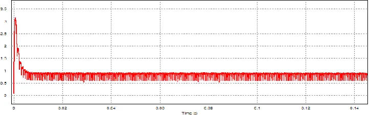
D. Current Controller with Filters
IJEDR1402047
International Journal of Engineering Development and Research (www.ijedr.org)1571
Fig. 28: Phase Current Waveform for phase AFig. 29: Three phase current waveforms
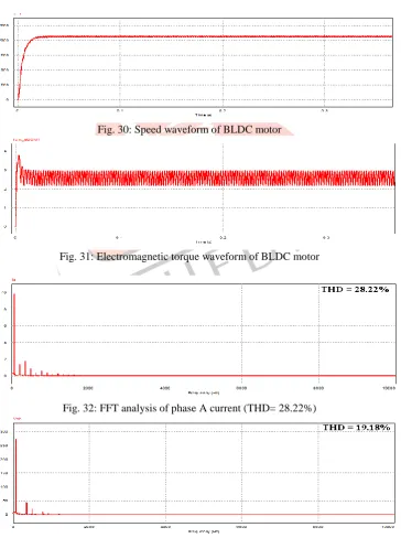
Fig. 30: Speed waveform of BLDC motor
Fig. 31: Electromagnetic torque waveform of BLDC motor
Fig. 32: FFT analysis of phase A current (THD= 28.22%)
IJEDR1402047
International Journal of Engineering Development and Research (www.ijedr.org)1572
TABLE ICOMPARISON OF TOTAL HARMONIC DISTORTION IN PHASE CURRENT AND LINE VOLTAGE
THD (%)
Voltage Controller Current Controller
Without Filter With Filter Without Filter With Filter
Phase Current 72.61% 30.52% 30.25% 28.22%
Line Voltage 53.70% 36.76% 32.62% 19.18%
VII.CONCLUSION
In this paper the different control strategy for BLDC machines has been presented. Torque ripples have been reduced by using voltage controller with filters. So in order to minimize the filter cost, current controller is presented. It is mainly based on generation of quasi square wave currents using only one current controller for the three phases instead of three current controllers. The main advantages of this strategy are it is very simple control scheme and phase currents are kept balanced and current is controlled through a dc component, and hence phase over currents are eliminated. The ripple content in the voltage and current waveforms are observed with and without filter. Here it is observed that when filter is used the torque and speed ripples are reduced more, and we have used both current control technique to smoother current which have direct effect on the output torque of the motor and voltage ripples are reduced using the filters.
REFERENCES
[1] G. Ranjith Kumar, K.N.V. Prasad, M. Arun Noyal Doss, “Improve the transient response of speed and torque ripple minimization of the BLDC motor by varies controllers,” In International conference on computer communication and informatics, IEEE, 2012, PP 1577-1583.
[2] M. Arun Noyal Doss, E. Premkumar, G. Ranjith Kumar, Jahir Husssain, “Harmonics and torque ripple reduction of brushless DC motor (BLDCM) using cascaded H-bridge Multilevel inverter,” In International Conference on power, energy and control (ICPEC), IEEE-2013, PP 296-299.
[3] M. Arun Noyal Doss, Subhranshu Sekar Dash, D. Mahesh, V. Marthandan, “A Model predictive control to reduce torque ripple for brushless DC motor with inbuilt stator current control,” In Universal Journal of Electrical and Electronic Engineering, 2013, PP 59-67.
[4] Yong Lui, Z. Q. Zhu, “Commutation-torque-ripple minimization in direct torque controlled PM Brushless DC drive” IEEE trans. Industry Applications, Vol.43, No.4, August 2007. PP 1012-1021.
[5] Karthikeyan, J. and R. Dhansekaran, 2010. Simulation and implementation of current control of BLDC motor based on a common dc signal. Int. J. Eng. Sci. Technol., 2: 1632-163.
[6] Lu, H., L. Zhang and W. Qu, 2008. A new torque control method for torque ripple minimization of BLDC motors with un-ideal back EMF. IEEE Trans. Power Electr., 23:950-958. DOI: 10.1109/TPEL. 2007.915667.