A Hybrid Multichannel Processing Method for Spaceborne
Hybrid Phased-MIMO SAR with Application
to Multi-Direction Swath Imaging
Lele Zhang* and Dianren Chen
Abstract—This paper proposes a hybrid multichannel processing method for spaceborne Hybrid Phased-MIMO SAR (HPMSAR) that can achieve different applications of multi-direction swath imaging on the same platform. The method is optimal because it is a combination of two-dimension (2-D) advanced digital beamforming (DBF) technology and multichannel pre-filter technology for high-resolution wide-swath SAR signal processing. Multichannel signal processing technology for future spaceborne SAR will no longer be single and this combination may be the best choice. The proposed method could avoid spectrum aliasing caused by low pulse repetition frequency (PRF), separate the overlapped echoes caused by different subpulses corresponding to multi-direction swathes and remove the range ambiguity and azimuth ambiguity deeply. At first, we build the signal model of HPMSAR system. Furthermore, the pre-filter design is presented by using matrix inversion method. Then, we address different methods applied to 2-D DBF and propose the advanced linearly constrained minimum variance (LCMV) method. Image results on simulated distributed targets validate the proposed hybrid multichannel processing method.
1. INTRODUCTION
Spaceborne synthetic aperture radar (SAR) systems in forthcoming surveillance and reconnaissance tasks have to meet increasingly severe demands. Conventional pulsed SAR systems, specifically single-channel systems, are inherently restricted with respect to their imaging capability. In the next generation of top-level spaceborne SAR systems, many kinds of tasks will be achieved on the same platform. Particularly, the future spaceborne SAR tasks:
• High-resolution and wide-swath are the fundamental requirements for future spaceborne SAR system. A high resolution requires a broad beam, which needs a large PRF in order to sample adequately. The high PRF in turn limits the swath width. A multichannel unambiguous SAR signal reconstruction technology in [1] was presented to solve this problem. In [2, 3], multidimensional waveform encoding technology was firstly proposed and the methods of beamsteering in elevation and multidimensional waveform encoding in azimuth were presented for the High-resolution and wide-swath (HRWS) system.
• An ultra-wide swath much wider than 300 km is desired to shorten the revisit period with complete global coverage from a satellite, and high azimuth resolution below 5 m is beneficial to obtain detailed information on specific areas. Multi-beam ScanSAR and Terrain Observation by Progressive Scans (TOPS) have been demonstrated in TerraSAR-X [4, 5] to achieve this goal. And the corresponding multichannel azimuth processing was proposed in [6].
Received 27 July 2015, Accepted 18 September 2015, Scheduled 24 September 2015
* Corresponding author: Lele Zhang (Andy [email protected]).
• The repeated acquisition of spaceborne SAR has opened numerous research areas and fields of applications, such as change detection or velocity measurements [7, 8]. This includes long term, midterm, short term and very short term for repetitions to dynamically monitor some different ground areas or micro-motion targets.
• Multi-Target recognition (MTR) [9] and Multi-Target Tracking (MTT) technology [10] in sapceborne SAR will be developed and widely used in military applications and civil applications in future.
All of these tasks can be attributed to the applications of multi-direction swath imaging. The realization of these and forthcoming SAR tasks demands the solution of many technological and methodological problems. The challenge is that, on the same platform, the two objectives need a new radar system and optimum signal processing technology. HPMSAR (Hybrid Phased-MIMO SAR) [11], which is a combination of the Hybrid MIMO Phased Array Radar (HMPAR) [12, 13] and SAR, will be the solution to achieve these tasks on the same platform. Although the real price of spaceborne HMPAR and radar data generated with the available instrument technology of today is too high, affordable operational instruments will play a key role in the very near future [14].
However, in such a system, overlapped echoes and ambiguities are always produced, and thus, signal reconstruction is necessary for SAR imaging. The signal reconstruction methods for multichannel SAR can be grouped into two categories: the first is based on the multichannel unambiguous reconstruction technology, which uses low PRF to achieve wide range coverage and the azimuth bandwidth isM·PRF, where M denotes the number of channels in azimuth [1]. The second is based on digital beamforming technology [15–18]. In [11], we further investigated the digital beamforming on receive in elevation for spaceborne HPMSAR. At present, spaceborne SAR, utilizing digital beamforming on receive, is increasingly being considered for future missions. But there are three problems:
1. System azimuth bandwidth is not always limited to ±M ·PRF/2, the energy outside this band is not well suppressed and finally gives rise to ambiguous contributions.
2. Residual scalloping as like in TOPS and ScanSAR will be caused by the grating lobe when the pointing angle is steered away from boresight, the grating lobe gain increases, and the main lobe gain decreases. Therefore, most of the grating lobes energy will also be folded back into the processed bandwidth, and this is the worst case causing a drop of performances.
3. Because of the multi-directional swath imaging, the overlapping echoes on receive are inevitable and the final image will appear overlapped arears.
And thus, the methods in [1–3, 6, 11, 15–18] may not be effective for the HPMSAR system. In order to achieve the high-resolution wide-swath image for this system, optimum signal processing is needed. In this paper a novel multichannel processing technology is proposed, which is a combination of 2-D advanced DBF and multichannel pre-filter technology for HPMSAR. The two key points of our proposed method are 2-D optimal weight design and appropriate “reconstruction” filter design, respectively. Firstly, a pre-filter is further proposed to reconstruct the signal without aliasing. Then, this paper presents the advanced adaptive DBF algorithm based on Linearly Constrained Minimum Variance (LCMV) and derives the optimal weights by adding additional constraints to guarantee proper reception of the desired signal and deep suppression of interference signal. A detailed investigation of this processing technology will be given in this paper.
This paper is organized as follows. Section 2 reviews HPMSAR system design including HPMSAR principle overview and signal model of HPMSAR. Then, Section 3 turns the focus to a hybrid multichannel processing method. Simulation experiment is performed in Section 4. Finally, concluding summaries are drawn in Section 5.
2. HPMSAR SYSTEM DESIGN 2.1. HPMSAR Principle Overview
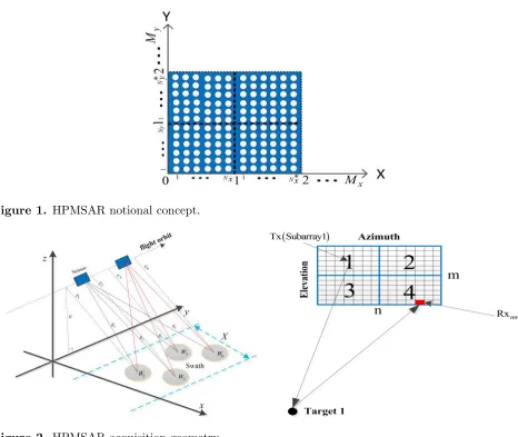
In HPMSAR, there is a rectangular array that can be referred to as a M N array, organized into M
Figure 1. HPMSAR notional concept.
Figure 2. HPMSAR acquisition geometry.
There are M =MxMy, N = NxNy, Nx(Ny) may be not equal to Nx∗(Ny∗), which will be setting separately for different applications, so that the transmit beampatterns will afford the greatest flexibility. We often use the case M = N because of its most flexibility in transmit beampattern design. Every subarray will produce a beampattern that illuminates the fraction 1/M of the total search volume, and if the beams are forming appropriately [19], transmit energy will be distributed evenly for the entire search volume. When all M signals are perfectly correlative, and all M subarrays are pointed in the same direction, then this planar array acts as one large phased array.
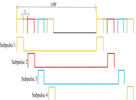
Figure 2 shows the HPMSAR acquisition geometry with four subarrays and the multi-direction rectangular transmit beampattern is shown in Fig. 3. For this system, all subarrays will be activated to emit subpulses in succession by dividing the total transmit pulse into multiple subpulses with an interval T0 that is the transmit interval between two subpulses as shown in Fig. 4, where the number
of subpulses corresponds to the number of subarrays forming the subbeams towards different swaths
Wk. The data from different subpulses are simultaneously received and superimposed into the same receiving window. Suppose that every swath corresponds to a point target with different slant ranges
R1, R2,. . .,Rk satisfying
2R1
c =
2R2
c +T0
2R2
c =
2R3
Figure 3. Transmit beampattern of HPMSAR. Figure 4. Subpulses sequence in transmit.
.. . 2Rk−1
c =
2Rk
c +T0 (1)
2.2. Signal Model of HPMSAR
Consider a HPMSAR system mounted on a moving platform. The system is composed of M transmit (Tx) subarrays and N receive (Rx) channels in each subarray and is equivalent to a multiple-input multiple-output radar system. The subarrays, in this case, have to be non-overlapped. And the number of RX channels is M×N. Every Tx subarray transmits orthogonal waveforms, and all RX antennas receive the backscattered echoes. The signals of the Tx/Rx antenna pairs are separated by signal processing. In this paper, we focus without loss of generality on the case of rectangular arrays. The signal model can be easily extended to the other configurations.
The reflected signal of a point target corresponding to the kth subpulse and the slant range
Rk(tm;R0) for each individual receiver channelnin the range-azimuth domain (ˆt−tm) may be described as
˜
sk
ˆ
t, tm
= ar
ˆ
t−Rk(tm;rk)
c −(k−1)T0
aa(tm) exp
jπkr
ˆ
t−Rk(tm;rk)
c −(k−1)T0
2
·exp
−j2π
λ Rk(tm;rk)−j2πfc(k−1)T0 , k= 1, . . . , M (2)
where ar(·) and aa(·) are the window function of the linear frequency modulation (LFM) signal and window function in azimuth respectively;fc,c,λandkrdenote the carrier frequency, the speed of light, the wavelength and the chirp rate, respectively.
To sum up (1) and obtain the expression
2Rk/c= 2R1/c−(k−1)T0 (3)
Inserting (3) into (2) leads to
˜
sk
ˆ
t, tm
=ar
ˆ
t−R1(tm;r1) c
aa(tm) exp
jπkr
ˆ
t−R1(tm;r1) c
2
·exp
−j2π
λ R1(tm;r1) (4)
where
R1(tm;r1) =
r21+ (vtm)2+
and Δxn is the physical along-track distance between the transmitter and the receiver n, v is the platform velocity, r1 is the closet slant range for point target 1. The received signal can be rewritten as
˜
sk ˆ
t, tm ∼
= ar
ˆ
t−R1(tm;r1) c
aa(tm) exp
jπkr
ˆ
t− R1(tm;r1) c
2
·exp
−j4π
λ r1 ·exp
−jπΔx
2
i 2λr1 ·
exp
−j2πv
2
s(tm−Δxi/2v)2
λr1
(6)
After taking the azimuth fast Fourier transform (FFT), the received signals from different directions in the range-Doppler domain can be computed as follows:
yˆt, fd;θk = M k=1 ˜ sk ˆ
t, fd
wHkAk(θk) = M
k=1
sk ˆ
t, fd
H(fd)wHkAk(θk)
= M
k=1
Aˆt, fd exp jπkr ˆ
t− R1(tm;r1) c
2
·exp
−j4π λ r1
·exp
−jπλr1
2v2f 2
d ·H(fd)wkH ·Ak(θk) (7)
where (·)H stands for the Hermitian transpose, H(fd) is the transfer function caused by the displaced phase center (DPC) imaging scheme and can be expressed by
H(fd) = exp
−jπΔx
2
n 2λr1 ·
exp
−j2πfd Δxn
2v (8)
This exponential will be removed in combination of matrix inversion method in Section 3. Ak(θk) is 2-D steering vector matrix of subarrayk defined as
Ak(θk) =ak(θk)⊗bk(θk) (9)
ak(θk),bk(θk) are the steering vector of every subarray towards directionθkin elevation and in azimuth respectively, which can be written as follows:
ak(θk) =
1 e−j(2πfcdsinθk/c) . . . e−j(2πfc(Ny−1)dsinθk/c) T (10)
bk(θk) =
1 e−j(2πfc·Δx1·sinθk/c) . . . e−j(2πfc(Nx−1)·ΔxNx−1·sinθk/c) T (11)
d denotes the element spacing, (·)T the transpose, and wk the unit-norm complex matrix of transmit beamforming weights associated with the kth subarray defined as
wk=
Ak(θk) Ak(θk)
(12)
Suppose that the reflected signal from the directionθk is received by the jth subarray, and it can be expressed as
˜ yj
ˆ
t, fd;θk
= ˜sk ˆ
t, fd
wHkAk(θk)Aj(θk) (13) The transmit coherent processing vector and the steering vector matrix of HPMSAR can be defined as
B(θk) =
wH1 A1(θk) wH2 A2(θk) . . . wHMAM(θk) T
(14)
A(θk) = [ A1(θk) . . . AM(θk) ] (15)
Stacking all the received signals by M subarrays into a signal vector, we have
yˆt, fd;θk
= ˜sk ˆ
t, fd
AT(θk)⊗Bk(θk) (16) where ⊗stands for the kronecker product. The measured signal is a combination of the backscattered echoes, interference signal and noise N. Assuming that the target of interest is observed in the background of B interfering targets with reflection coefficients {ρq}B
Gaussian noise with the powerσn2. So the received complex vector of array observations can be written as
Xˆt, fd;θ
= yˆt, fd;θk
+ B
q=1
zˆt, fd;θq
+N
= ˜sk
ˆ
t, fd
·AT(θk)⊗Bk(θk) + B
q=1
˜
sq
ˆ
t, fd
·AT (θq)⊗Bq(θq) +N (17)
3. A HYBRID MULTICHANNEL PROCESSING METHOD
The hybrid multichannel processing method is based on different approaches. This does not correspond to any current one, but it could be an optimum processing method for the future spaceborne HPMSAR. It can be easily applied on other multichannel radar system (ScanSAR, TOPS and HRWS). In order to achieve high-resolution wide-swath imaging from different directions, some problems must be solved as follows:
1. The aliased azimuth spectrum on receive is caused by a non-optimum PRF, i.e., non-uniformly spaced data samples.
2. The ambiguities in azimuth and range that is caused by the PRF selection and the sidelobes of transmit beampattern. When the pointing angle is steered away from boresight, grating lobes arise. The echoes corresponding to the grating lobes are also ambiguities. So these will influence the image quality.
3. Echoes of subpulses from different swaths will inevitably overlap in a certain echo receiving period. Overlapped areas are especially in the adjacent area between two subswaths.
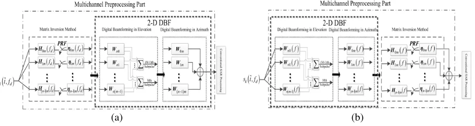
In this paper, our method, which is a combination of matrix inversion method and 2-D DBF, is introduced and the multichannel preprocessing part is our research key point as shown in Fig. 5. All signals are sampled, digitized, and stored before processing. The matrix inversion method aims at recovering the unambiguous Doppler spectrum by suppressing the ambiguous frequency components. The 2-D DBF corresponds to place nulls at angles where ambiguous Doppler frequencies and range ambiguities are situated and maximize the signal power to separate the overlapped echoes. A basic idea of the digital beamforming by cascaded networks is to introduce a trade-off between ambiguity suppression and optimized signal energy to improve the signal-to-noise-plus-interference ratios (SINRs). The order of the networks (matrix inversion method and 2-D DBF) and the combinations of the subaperture are in principle arbitrary as long as this structure allows for the multiplication of the respective patterns of the two stages in Figs. 5(a) and (b). Such networks show flexibility with respect to the receiving pattern (2-D DBF) and the effective sampling ratio (matrix inversion method) given by the number of different reconstructed channels that are directly linked to the number of subapertures
(a) (b)
of the M N array in azimuth and elevation respectively. The receiving elements could be mutually overlapping and this means that one could set the phase centers flexibly and obtain a wider PRF range to get the optimum PRF to minimize the nonuniform sampling. In addition, a large number of the receiving apertures are available enabling adaptive pattern control by adjusting the network’s weighting coefficients.
As the matrix inversion method and 2-D DBF do not affect the signal envelope, the beamwidth of the output signal is defined by the single element length, while the gain is determined by the number of channels that are combined in the second stage. Note that all processing could be applied a posteriori processing on the ground and consequently the system setting can be reconfigured arbitrarily to focus on the respective performance parameter of interest, be it ambiguity suppression, resolution, swath-width or Noise-Equivalent Sigma Zero (NESZ) [18].
In the following, the detail derivation of the two methods will be given as.
3.1. Matrix Inversion Method for Pre-filter Design
This section presents a method for reconstructing the SAR signal from the aliased multichannel signals. The approach presented in [1, 6, 18, 20] is based on the work in [21]. The essential idea of these techniques is to substitute high sampling frequency in space domain for high sampling frequency in the time domain by means of multiple receiver channels. Each of thenreceiver channels’ signals is mixed, digitized, and stored. In azimuth dimension, this enables a coherent combination of the n subsampled and hence aliased signals to a single output signal that is sampled with n·PRF and free of aliasing. We have introduced the transfer function H(fd) in Section 2.2. Suppose that n×1 vector is defined by
Hl(fd) = exp
−jπ
Δx2l 2λr1
+Δxl
v (fd+l·P RF) ·1n (18)
where1n= [ 1 1 . . . 1 ]T is the vector ofn ones. One defines then×nmatrix
H(fd) = [ H0(fd) H1(fd) . . . Hn−1(fd) ] (19) The set of filters ηl(fd) used to retrieve the signal is obtained by computing the inverse matrix of
H(fd), and the vectors are defined by
ηl(fd) =HHinv(fd)·1ln (20)
where1ln= [ 0 0 . . . 1 . . . 0 ]T and
Hinv(fd) =H−1(fd) (21) Arranging the filters ηl(fd),l= 0, . . . , n−1, in Hinv(fd) yields
Hinv(fd) = ⎡ ⎢ ⎢ ⎢ ⎣
ηH0 (fd)
ηH1 (fd) .. .
ηHn−1(fd) ⎤ ⎥ ⎥ ⎥
⎦ (22)
One notes that whenH(fd) is not a square matrix and the number of its columns is smaller than the number of channels m, then |H(fd)| = 0 and its rank is r(r > 0). This matrix is therefore not invertible, and the matrix inversion method cannot be applied in this case. To mitigate this problem, two solutions can be thought of. The first solution is taking the singular value decomposition (SVD) of
H(fd), its expression is given as
H=USVH =U 0 00 VH (23)
By definition, the SVD matricesU andV are unitary, andSis diagonal,= diag(ρ1, ρ2, . . . , ρr),
ρ1, ρ2, . . . , ρr are the nonzero singular value of H(fd). And the generalized inverse matrix ofH(fd) can be expressed as
H+=V −
1 0
0 0 U
where (·)+ denotes the generalized inverse matrix, and this inverse matrix could be computed easily. Another solution is to utilize the full rank decomposition ofH, leading to
H=BC (25)
whereB and C, which could be derived through the elementary transformation ofH, are the matrices that the rank is same as H. One could get
H+=CHCCH−1BHB−1BH (26) So the 2-D filters of HPMSAR is
H2−D(fd) = ⎡ ⎢ ⎢ ⎢ ⎢ ⎣
ηH
00(fd) η01H(fd) . . . ηH0(m−1)(fd)
ηH
10(fd) η11H(fd) . . . ηH1(m−1)(fd) ..
. ... ... ...
ηH
(n−1)0(fd) η(Hn−1)1(fd) . . . ηH(n−1)(m−1)(fd)
⎤ ⎥ ⎥ ⎥ ⎥
⎦ (27)
3.2. Digital Beam-Forming in Elevation
HPMSAR system uses DBF on receive to steer in real time a narrow beam toward the direction of arrival of the radar echo reflected from the subswaths, exploiting the one-to-one relationship between the radar subpulses travel time and its direction of arrival (this is also referred to as SCan-On-Receive (SCORE) mode).
3.2.1. Matrix Inversion Method
For themth subswath echoes, the corresponding elevation beamformer weight vectorWel, which needs to steer nulls in the directions where its ambiguous components come from, can be obtained by solving the following matrix equation:
VelWel=H (28)
where Vel is the receive array manifold matrix with rows being the steering vectors associated with signal and ambiguity components,H= [ h1 h2 . . . hn ]T, the desired signal hp = 1, the others are zero,Wel can be computed and expressed as follows:
Wel=Vel−1H (29)
The maximum number of ambiguities that can be suppressed corresponds to the number of Rx channels in elevation (or in azimuth). One can select which ambiguities should be suppressed and may choose not to suppress weak ambiguities (i.e., ambiguities with signal power below the noise power or slightly above the noise power) so as to preserve the signal noise ratio (SNR).
3.2.2. MVDR
A second class of beamformers is known as minimum variance distortionless response (MVDR) beamformer [22] which is based on Capon’s method [23]. This method preserves the signal of interest while minimizing contributions to the beamformer output due to interference from other directions than the direction of interest and noise. This approach can be understood as a spatial matched filter. It is optimal with respect to the SNR. This can be expressed as the following optimization problem
min
W W
HR
XXW s.t. aHW= 1 (30)
whereRXX is the interference-plus-noise covariance matrix, ais the steering vector in elevation (or in azimuth) and expressed as
a(θk) =
1 e−j(2πf0dsinθk/c) . . . e−j(2πf0(m−1)dsinθk/c) T (31)
The optimum conjugate complex weight vectorW in closed form is given as
Wel=
R−XX1 a aHR−1
XXa
Suppose that there are melements for reception and the covariance inverse matrix is expressed in the terms of feature space theory as follows
R−XX1 = B
i=1
λ−i 1eieHi + m
i=B+1
σ−n2eieHi =σ−n2
I−
m
i=1
λi−σn2
λi eie H i
(33)
whereei is the eigenvector of theRXX,λi corresponds to its eigenvalue,I is identity matrix.
3.2.3. LCMV
A method known as linear constraint minimum variance (LCMV) beamforming [22] provides an analytic solution to this problem. The problem is stated as follows
min
W W
HR
XXW s.t. CHW =f (34)
whereCis the constraint matrix, and the vectorf specifies the corresponding constraint value for each vector. C includes two parts and their analytical expressions have the form
C= [ a(θk) a(θq) ] (35)
a(θk),a(θq) are the steering vectors of desired signal and interference signal and
f = [ 1 0 ]T (36)
The closed-form solution is
Wel=R−XX1 C
CHR−XX1 C−1f (37)
3.2.4. Advanced LCMV
Although adaptive weighting, which is discussed before, can set nulls at the direction of interference, the sidelobe shape on receive is often too high and it is not desirable. In practical applications, adaptive weighting is not real-time and the weight of the current application is the result of a period of observation of the previous training data, which means that the adaptation process at this time is effective for prior interference signal. When the environment of interference changes rapidly, the system is powerless to sudden interference and system performance will deteriorate greatly.
So we want to achieve desired quiescent response with an overall low sidelobe and set nulls at the jammer direction simultaneously. This Adaptive Pattern Control (APC) method is advanced LCMV proposed in this paper. In a way, this could counteract performance degradation caused by unknown interference. A linearly constrained beamformer can be formulated as that of finding the weight vector
W which minimizes the output power. min
W W
HR
XXW s.t. CHW =f (38)
It is well known that the optimal solution of the minimization problem defined above is
Wel=R−XX1 C
CHR−XX1 C−1f (39) and then we will design C, f and R−XX1 appropriately and R−XX1 has been given in (33). Where C
includes three parts and their analytical expressions have the form
C= W0 C0 a(θq)
(40)
and
f = [ 1 0 . . . 0 ]T (41)
W0 =
W0
WH0 W0
(42)
whereW0 denotes the weighting coefficients of the desired quiescent response [24, 25]. C0 is to prevent
in the literature [26]. In order to achieve the desired adaptive low sidelobe and reduce the small eigenvalue interference for its eigenvector, we apply the technique of diagonal loading in [27] that adds the appropriate value Qto every eigenvalue. So the expression (39) can be rewritten as
Wel =
I−
m
i=1
λi+Q−σn2
λi+Q eie H i
C
CH
I−
m
i=1
λi+Q−σ2n
λi+Q eie H i
C
−1
f (43)
3.3. Digital Beam-Forming in Azimuth
This space-time approach is based on adaptively adjusting the weighting coefficients of the azimuth channels to steer the nulls to the angles corresponding to the ambiguous Doppler frequencies. This corresponds to a spatial filtering of the data to suppress ambiguous frequencies in the azimuth signal. The coherent combination of all signals in a dedicated multichannel processor enables the generation of a HRWS image. DBF in azimuth principally applies in the same way as it does in elevation.
Suppose that the Doppler bandwidth of the pointlike target from different subswaths is−Bp/2≤
fsig ≤ Bp/2, where fsig = 2vsinϕ/λ, Bp is Doppler bandwidth, ϕ is azimuth squint angle and the azimuth ambiguity can be expressed as
±k·fce−Bp/2≤famb ≤ ±k·fce+Bp/2 (44) andfamb=fsig±k·fce,fcebeing the magnitude of Doppler centroid associated with the squint transmit subbeams. kis ambiguous signal order, and the first-order ambiguities are primary contributors to the total azimuth ambiguity power.
In fact, the Doppler spectrum is not strictly band limited due to the sidelobes of the azimuth antenna pattern. As a consequence, Doppler frequency components outside the sampling interval −PRF/2 ≤ fsig ≤ +PRF/2 are folded back into the processed Doppler frequency range, which will produce ambiguities. In addition, most of the grating lobes energy is also folded back into the processed bandwidth, and this is the worst case causing a drop of performances, so we must consider it. All of these ambiguities could be suppressed by advance LCMV method.
So the system 2-D weighting of HPMSAR is given by
Wsystem=
⎡ ⎢ ⎢ ⎢ ⎣
W00 W01 . . . W0(m−1)
W10 W11 . . . W1(m−1)
..
. ... ... ...
W(n−1)0 W(n−1)1 . . . W(n−1)(m−1)
⎤ ⎥ ⎥ ⎥
⎦ (45)
3.4. Computational Performance
In our proposed hybrid multichannel processing method, pattern synthesis methods for desired quiescent response, which are derived from the principle of adaptive arrays, achieve their results by solving either a single or a sequence of least squares optimization problems. Due to the existence of efficient, closed-form solutions to the least squares problem, they offer significant computational simplicity [24, 25]. Here, only the main computational load arising from the matrix inversion is considered, it has (n3+b·(n+m) +a)
computational complexity, where b and aare related with the number of columns of C in (40). From this result, we know that depends upon the number of the receiving antennas, so the configuration of
M N array will directly affect the calculation. In order to obtain a tradeoff between improvements in performance and the required computational complexity, the number of subarrays and subapertures in each subarray and the dimension of subaperture used should be properly selected.
4. SIMULATION RESULTS
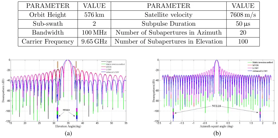
Table 1. System parameters used in the simulation.
PARAMETER VALUE PARAMETER VALUE
Orbit Height 576 km Satellite velocity 7608 m/s
Sub-swath 2 Subpulse Duration 50µs
Bandwidth 100 MHz Number of Subapertures in Azimuth 20 Carrier Frequency 9.65 GHz Number of Subapertures in Elevation 100
(a) (b)
Figure 6. Beampatterns of the HPMSAR system. (a) Elevation patterns. (b) Azimuth patterns.
In Fig. 6, by comparing the beampatterns on receive, our proposed advanced LCMV in blue color has a −40 dB and −30 dB uniform sidelobe level approximately and sets two nulls which are located at 31.28◦, 38◦ in Fig. 6(a) and at −1.889◦, 1.889◦ in Fig. 6(b), respectively. From the results, we can see that the advanced LCMV approach works well for the beampattern at the receiving. For better illustration, the range compression results and azimuth compression results are given in Fig. 7 and Fig. 8.
Figures 7(a) and (b) present the raw data with the two ambiguities and their magnitude is−6.4 dB. White noise is added to the data to get the SNR of 0 dB and 20 dB respectively for the whole radar system. In order to know the influence of noise, every method will be simulated in different SNRs. The
(a) (b) (c) (d)
(i) (j) (k) (l)
Figure 7. Performance of different beamforming methods in elevation at SNR = 20 dB and SNR = 0 dB. (a) and (b) Raw data. (c) and (d) Matrix inversion method. (e) and (f) MVDR method. (g) and (h) LCMV method. (i), (j), (k) and (l) Advanced LCMV method.
(a) (b) (c) (d)
(e) (f) (g) (h)
(i) (j) (k) (l)
Figure 8. Performance of the combination of different beamforming methods and pre-filter technology in azimuth at SNR = 20 dB. (a) and (b) Raw data. (c) and (d) Matrix inversion method. (e) and (f) MVDR method. (g) and (h) LCMV method. (i), (j), (k) and (l) Advanced LCMV method.
ambiguities are suppressed below noise level by using matrix inversion method and LCMV method in Figs. 7(c), (d), (g) and (h). Figs. 7(e) and (f) show results of the MVDR method and the ambiguities are −22.6 dB approximately. The performance of advanced LCMV method shows that the two ambiguities are below −40 dB by using low sidelobe technology in Figs. 7(i) and (k), and removed completely by setting nulls as shown in Figs. 7(j) and (l).
in azimuth we only use SNR = 20 dB. Fig. 8(a) presents the raw data without preprocessing, which is generated for a given undersampling frequency. Fig. 8(b) shows the reconstructed data by using pre-filter, and the aliasing phenomenon is not existent. In Figs. 8(c), (e), (g), (i) and (j), the aliasing is still existent by using different methods without pre-filter. After the pre-filter, the aliasing and ambiguities are suppressed simultaneously in Figs. 8(d), (f), (h), (k) and (l). Particularly, Fig. 8(k) shows the ambiguities is below −30 dB, and the aliasing and ambiguities are eliminated in Fig. 8(l) by using our proposed method.
There is one desired target surrounded by ambiguities in azimuth and range as shown in Fig. 9(a). This condition is worst with serious aliasing. After the pre-filter, the aliasing is avoided, but the ambiguities are still serious in Fig. 9(b). Figs. 9(c) and (d) are the results after beamforming in elevation
(a) (b) (c)
(d) (e)
Figure 9. Performance of the hybrid multichannel processing method for HPMSAR system at SNR = 20 dB. (a) Rada data without pre-processing. (b) Pre-filter. (c) Beamforming in elevation. (d) Beamforming in azimuth. (e) Final result.
(a) (b)
and in azimuth respectively. The ambiguities are only suppressed in respective direction and this is not our final goal. It can be clearly seen that the desired target is well focused via the proposed hybrid multichannel processing approach as shown in Fig. 9(e). Fig. 10 presents the results at SNR = 0 dB that the desired signal is unambiguously retrieved, and the noise level is also declined.
In fact, there is always useful echo, that is, for each point on the swath, preprocessed by the hybrid multichannel processing method, whereas the aliasing condonation is avoided, and the ambiguous echoes are strongly attenuated,then overlapped echoes will be separated. Simulation results validate the processing approach.
5. CONCLUSION
HPMSAR will be increasingly used in future spaceborne SAR systems. This paper reports the system design aspects for HPMSAR. A novel hybrid multichannel processing method is proposed, which is most likely to be the best choice for signal processing in future spaceborne HPMSAR system or other HRWS systems. And the simulation results show excellent system performance compared with conventional methods. However, the results obtained for HPMSAR do not represent the full possible performance but give a good indication about the potentials and challenges for the operation of multichannel systems.
As a next step, based on the analysis of HPMSAR, focus should be on the orthogonal waveform design, different parameter selections and system optimization. It is worth nothing that the optimum design of HPMSAR system can be a combination of the transmit beamforming and hybrid multichannel processing method in terms of the different applications of multi-direction swath imaging. These features make HPMSAR the preferred candidate for future multi-direction swath imaging applications. In conclusion, such systems open up an entirely new field of SAR operation and introduce a new degree of freedom in SAR system design.
ACKNOWLEDGMENT
The authors would like to thank the editor and anonymous reviewers for their valuable time, comments, and suggestions to improve the quality and readability of this paper.
REFERENCES
1. Krieger, G., N. Gebert, and A. Moreira, “Unambiguous SAR signal reconstruction from nonuniform displaced phase center sampling,”IEEE Geosci. Remote Sens. Lett., Vol. 1, No. 4, 260–264, 2004. 2. Krieger, G., N. Gebert, and A. Moreira, “Multidimensional radar waveforms,” Geoscience and
Remote Sensing Symposium, 4937–4941, Barcelona, 2007.
3. Krieger, G., N. Gebert, and A. Moreira, “Multidimensional waveform encoding: A new digital beamforming technique for synthetic aperture radar remote sensing,” IEEE Transactions on Geoscience and Remote Sensing, Vol. 46, No. 1, 31–46, 2008.
4. De Zan, F. and A. M. Guarnieri, “TOPSAR: Terrain observation by progressive scans,” IEEE Transactions on Geoscience and Remote Sensing, Vol. 44, No. 9, 2352–2360, 2006.
5. Meta, A., J. Mittermayer, P. Prats, et al., “TOPS imaging with TerraSAR-X: Mode design and performance analysis,” IEEE Transactions on Geoscience and Remote Sensing, Vol. 48, No. 2, 759–769, 2010.
6. Gebert, N., G. Krieger, and A. Moreira, “Multichannel azimuth processing in scanSAR and TOPS mode operation,” IEEE Transactions on Geoscience and Remote Sensing, Vol. 48, No. 7, 2994– 3008, 2010.
7. Wollstadt, S., P. Prats-Iraola, P. Lopez-Dekker, et al., “Bidirectional SAR imaging mode,” IEEE Transactions on Geoscience and Remote Sensing, Vol. 51, No. 1, 601–614, 2013.
9. Perissin, D. and A. Ferretti, “Urban-target recognition by means of repeated spaceborne SAR images,”IEEE Transactions on Geoscience and Remote Sensing, Vol. 45, No. 12, 4043–4058, 2007. 10. Chang, Y.-L., C.-Y. Chiang, and K. Chen, “SAR image simulation with application to target
recognition,”Progress In Electromagnetics Research, Vol. 119, 35–57, 2011.
11. Zhang, L. and D. Chen, “Digital beamforming on receive in elevation for spaceborne hybrid phased-MIMO SAR,” Progress In Electromagnetics Research M, Vol. 40, 153–166, 2014.
12. Hassanien, A. and S. A. Vorobyov, “Phased-MIMO radar: A tradeoff between phased-array and MIMO radars,”IEEE Transactions on Signal Processing, Vol. 58, No. 6, 1–33, 2010.
13. Fuhrmann, D. R., J. Paul Browning, and M. Rangaswamy, “Signaling strategies for the hybrid MIMO phased-array radar,”IEEE Journal of Selected Topics in Signal Processing, Vol. 4, No. 1, 66–78, 2010.
14. Ludwig, M., C. H. Buck, F. Coromina, and M. Suess, “Status and trends for space-borne phased array radar (INVITED),”IEEE MTT-S International Microwave Symposium Digest, 2005. 15. Huber, S., M. Younis, A. Patyuchenko, et al., “Digital beam forming concepts with application to
spaceborne reflector SAR systems,”International Radar Symposium (IRS), 1–4, 2010.
16. Feng, F., S. Li, W. Yu, P. Huang, and W. Xu, “Echo separation in multidimensional waveform encoding SAR remote sensing using an advanced null-steering beamformer,” IEEE Transactions on Geoscience and Remote Sensing, Vol. 50, No. 10, 4157–4171, 2012.
17. Krieger, G., M. Younis, S. Huber, et al., “Digital beamforming and MIMO SAR: Review and new concepts,”Synthetic Aperture Radar, 11–14, 2012.
18. Younis, M., S. Huber, A. Patyuchenko, et al., “Performance comparison of reflector-and planar-antenna based digital beam-forming SAR,” International Journal of Antennas and Propagation, 1–13, 2009.
19. Bucci, O. M., T. Isernia, and A. F. Morabito, “An effective deterministic procedure for the synthesis of shaped beams by means of uniform-amplitude linear sparse arrays,” IEEE Transactions on Antennas and Propagation, Vol. 61, No. 1, 169–175, 2013.
20. Gebert, N., G. Krieger, and A. Moreir, “Digital beamforming on receive: Techniques and optimization strategies for high-resolution wide-swath SAR imaging,” IEEE Transactions on Aerospace and Electronic System, Vol. 45, No. 2, 564–592, 2009.
21. Brown, J., “Multi-channel sampling of low-pass signals,”IEEE Trans. Circuits Syst., Vol. 28, No. 2, 101–106, 1981.
22. Trees, H. L. V., Optimum Array Processing, Wiley, Hoboken, NJ, 2002.
23. Capon, J., “High-resolution frequency-wavenumber spectrum analysis,” Proceedings of the IEEE, Vol. 57, No. 8, 1408–1418, 1969.
24. Tseng, C.-Y. and L. J. Griffiths, “A simple algorithm to achieve desired patterns for arbitrary arrays,” IEEE Transactions on Signal Processing, Vol. 40, No. 11, 2737–2746, 1992.
25. Wang, F., R. Yang, and C. Frank, “A new algorithm for array pattern synthesis using the recursive least squares method,”IEEE Signal Processing Letters, Vol. 10, No. 8, 235–238, 2003.
26. Tseng, C.-Y., “Minimum variance beamforming with phase-independent derivative constraints,”
IEEE Transactions on Antennas and Propagation, Vol. 40, No. 3, 285–294, 1992.
27. Carlson, B. D., “Covariance matrix estimation errors and diagonal loading in adaptive arrays,”