A Frequency Reconfigurable Meandered Slot Cut Rectangular Patch
Antenna Using PIN Diodes
Rocktotpal Baruah and Nidhi Saxena Bhattacharyya*
Abstract—A frequency reconfigurable patch antenna is proposed. The antenna has a rectangular patch with two meandered slots. It can be switched between four bands using two PIN diodes by altering current distribution across the slot edges. The overall dimension of the antenna patch is 11.51 mm×8.37 mm and fabricated on an FR4 substrate. The design is investigated by simulation and measurement, and the result includesS11parameters, radiation patterns, measured directivity and
gain. With different combinations of PIN diode biasing conditions, the antenna can be set to 6.80 GHz, 7.34 GHz, 7.80 GHz and 8.18 GHz, which collectively covers a continuous frequency range of 1.80 GHz (−10 dB bandwidth). The antenna also shows consistent radiation patterns at all the reconfigured frequency bands with an average beam width of about 75◦. In the accessible frequency range, an average gain of 5.14 dBi and low level of cross polarizations are also recorded. A good agreement between measured and simulated results validates the presented concept of frequency reconfiguration.
1. INTRODUCTION
Reconfigurable antennas (RA) have gained a lot of attention for their potential applications in devices with multiple wireless standards. Recently, various efforts, including theoretical and experimental studies have been made to realize additional performance enhancement offered by RA. Antennas with switchable operating frequency have the ability to accommodate new services according to the user utility and can cover multiple wireless standards. They can eliminate the sophisticated filters used in most of the wideband antennas [1]. A narrow band antenna with discrete frequency switching is a suitable method in this aspect. However, continuously tunable antennas can also be used for those purposes, but in that case, the accessible range is generally less than discrete frequency approach [2]. Along with the reconfigurability, other issues such as consistency of radiation characteristics, simple and low profile design, practical applicability of the techniques adopted are also crucial for modern handheld and wearable wireless applications [3].
There are several ways of tuning viz. electrical, optical and mechanical ones, which have been investigated to develop a reliable reconfigurable system for planar antennas [4–10]. Among these techniques, the ease of integration, fast switching speed and high rate of repeatability make electrical tuning most preferable. The electrical method includes PIN diodes, varactors and RF-MEMS as the switching elements, and each of these elements has its own advantages and limitations [2, 11]. In a reconfigurable antenna, geometry of the patch also has great significance. Structures like slot cut patches, parasitically coupled elements, nested radiators are of great interest and extensively investigated [12–16]. In terms of operational frequency shifting, slotted structures offer more versatility than the nested one. Slot antenna offers frequency tunability over a wide range by simply altering slot configuration, thus, covers a large frequency range without much change in its physical dimension [17], which helps in making the antenna compact. On the other hand, from the studies conducted on nested
Received 12 June 2017, Accepted 15 August 2017, Scheduled 25 August 2017
* Corresponding author: Nidhi Saxena Bhattacharyya ([email protected]).
structures, it has been observed that the antenna patch dimension increases with the tunable frequency range [13, 14, 18].
Recently, a number of efforts have been reported to demonstrate the frequency adaptability by incorporating electrical switches into planar slot antennas. In [19], a slot antenna with nine reconfigured bands (1.98 GHz–3.59 GHz) is presented. A switchable multiband operation over a wide range about 4.60 GHz is reported in [20]. However, in both the antennas, variations of radiation patterns at different frequencies are recorded. A continuously tunable antenna is proposed in the approach [21], where a single PIN diode and varactor are used. This investigation offers a continuous tuning, covering a range from 0.42 GHz–1.48 GHz with a consistent radiation pattern over the whole tuning range. Conversely, the relatively high value of biasing voltage used for tuning makes it less suitable for some handheld and wearable operations with limited power source [11]. A theoretical investigation of slot and slit loaded patch antenna for frequency reconfiguration within a span of about 0.6 GHz is presented in [22]; however, the approach uses a large number of switches which may increase system complexity and limit the scope of practical realization.
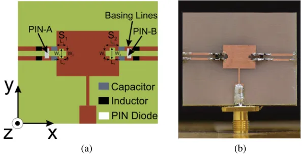
This paper presents a meandered slot geometry based antenna with a switchable operating band. A prototype is simulated and fabricated as shown in Fig. 1. The design uses the advantage of meandered slot to accommodate a lower resonant frequency with a relatively smaller patch. The desired adaptability is achieved by changing slot configuration through PIN diode. Fast switching speed, low operating voltage and edge of integration are the factors which make it more suitable than the other two types. The objective is to demonstrate a method of frequency reconfiguration with stable radiation characteristics. Antenna size, simplicity of the design, power consumption of the reconfiguring circuitry are also taken into consideration. The proposed antenna is a single band antenna with an ability of frequency hopping over a continuous range.
The proposed design is tested for stable radiation characteristics, and frequency reconfigurability and performances are found satisfactory. The work provides a simple and efficient way to realize multiple closely spaced frequency bands within a limited space. The antenna design and performance parameters are discussed in the following sections.
2. ANTENNA DESIGN AND CONFIGURATION
The proposed meandered slot antenna is a modified form of a rectangular microstrip patch antenna (RMA). The designed antenna has two non-identical cross shaped meandered slots etched in the middle of non-radiating edges of a standard RMA (Fig. 1(a)). The presence of these slots increases the electrical length of the non-radiating edge, which eventually elongates the surface current paths. Due to the dependence of the resonant frequency of an antenna on the length of the current path, this elongation results in a lowering of frequency from the originally designed value, i.e., resonating notch of the base RMA. In this work, an 8 GHz RMA is taken as a base antenna, and two slots of non-identical dimensions are incorporated along the non-radiating edges to achieve the targeted reconfigurability.
(a) (b)
A gradual shift in resonant frequency is made by stepped incorporation of slots in the order: No Slot–SlotS1–SlotS2–SlotS1and SlotS2together. Precise slot dimensions are optimized using CST MW
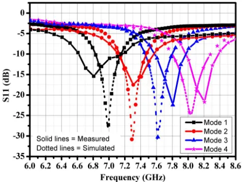
Studio for gradual shifting of individual band positions, maintaining a continuous−10 dB range as shown in Fig. 2. The optimization of slot dimension includes (i) Cascading of band positions, (ii) Maximization of the −10 dB frequency range. However, beyond 6.5 GHz for this antenna gain decreases drastically, and it limits the range over which frequency can be reconfigured. This is due to the increasing input impedance mismatch as the antenna feed line is designed for 8.00 GHz only. The optimized dimension of each slot is listed in Table 1. The cross-shaped slot is a repeating structure housing two identical scaled versions of itself. With the incorporation of this structure, the non-radiating edge of the rectangular patch takes the form of a second order quasi Minkowski curve [23, 24]. Because of the meandered nature, the curve pushes the patch boundary inside, showing a trend to fill the area within. This will eventually extend the length of the non-radiating edge into the interiors of the patch without increasing the overall antenna dimension. As a result, the proposed antenna is capable of radiating at a much lower frequency centered at 6.80 GHz with a relatively smaller sized patch dimension ofL= 8.27 mm andW = 11.41 mm, which is conventionally designed to resonate at around 8.00 GHz. For a rectangular patch to resonate at 6.80 GHz, without these slots, the dimension should beL= 9.89 mm andW = 13.42 mm. The lowest operating frequency of the antenna is 6.60 GHz when slots are introduced to the radiator. It provides a shifting about 1.4 GHz with respect to the operating band of the antenna without slots, though the overall patch dimensions are unaltered.
Table 1. Slot dimension.
SlotS1 L1= 1.80 mm L2= 1.80 mm W1 = 1.80 mm W2 = 1.00 mm
SlotS2 L3= 2.50 mm L4= 1.00 mm W3 = 1.00 mm W4 = 2.20 mm
distribution leading to separate resonating notches. With the specific dimensions given in Table 1, the designed antenna can be reconfigured to four different positions by independently controlling each PIN diode over a continuous range of frequency.
Along with the frequency hopping, the design of the antenna also helps in maintaining the shapes of radiation patterns at all the reconfigured bands. This particular design provides a constant overall physical dimension of the antenna patch even with the extensive variations of the effective current paths, for all the operating modes. This is accomplished by the insertion of cross shaped meandered slots to the patch geometry, which forces surface currents to travel a much longer path within a small area near non-radiating edges. This results in minor variations of the filed distributions across the periphery of the patch for all the switching conditions and generates almost identical radiation patterns at all the reconfigured frequencies.
3. RESULTS AND DISCUSSION
The proposed antenna is fabricated on a 1.6 mm thick FR4 substrate of dielectric constant 4.3 (Fig. 1(b)) and tested for experimental verification. All the parameters are measured using Agilent VNA (E8362C) and Antenna Measurement System from Diamond Engineering, USA.
Figure 2. Measured and simulatedS11 parameters (Solid lines represents measured result and dotted
lines represents simulated results).
The measured and simulated S11 parameters of the meandered slot antenna are shown in Fig. 2.
Initially, when both diodes are OFF, a resonating notch occurs at 6.80 GHz (Mode 1). In Mode 2, frequency is shifted to 7.34 GHz by putting PIN-A to ON condition, which is connected to SlotS1 and
for Mode 3, and it is moved to 7.80 GHz when PIN-B attached to SlotS2 is ON. Finally, with both the
diodes in ON state, the antenna resonates at 8.18 GHz. Different PIN diode states for all the modes and corresponding frequencies are given in Table 2. From the measured results it is observed that the proposed antenna offers a single operating band which can be set to four positions in the electromagnetic spectrum by changing the PIN diode’s biasing condition. It should also be noted that precise selection of slot dimensions helps in hopping of frequency in a cascaded manner to cover a range of 1.80 GHz (6.6 GHz–8.4 GHz). Simulated results forS11 parameters are also in good agreement with the measured
ones. However, slight variations could be due to the effect of fabrication tolerances.
(d)
(a) (b)
(c)
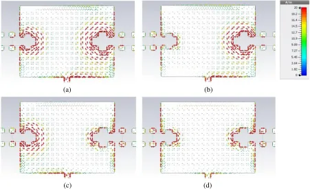
Figure 3. Surface current distribution: (a) Mode 1, (b) Mode 2, (c) Mode 3 and (d) Mode 4.
the slot edges but increase in the PIN network (Fig. 3(d)). In Figs. 3(b) and (c), only one PIN diode is alternatively set to ON mode. Fig. 3(b) depicts the decrease in current density across the perimeter of slot S1 and in Fig. 3(c) across slotS2.
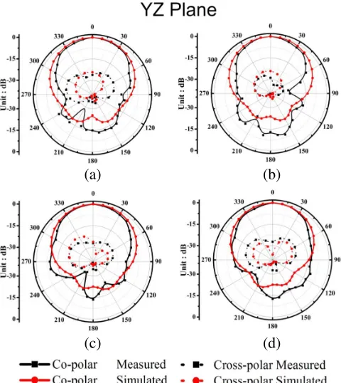
In Fig. 4 and Fig. 5, normalized radiation patterns of the antenna for all possible modes are presented. The designed antenna offers consistent radiation patterns at all reconfigured frequencies. In
XZ plane (Fig. 4), measured radiation pattern shows a fixed main lobe direction at 0◦ with an average −3 dB beamwidth about 74.89◦. Similar consistencies are also maintained in Y Z plane (Fig. 5), giving an average beamwidth of 76.98◦ with the main lobes at around 4◦. A low cross polarization level at each of the frequency is recorded. Simulated radiation patterns also show similar stability at all the switched frequencies. From the study, it can be said that effect of biasing lines on the radiation patterns is very low as the measured patterns are almost identical to that of a standard RMA.
Performances of the antenna in terms of directivity and gain are also tested, and results indicate a fairly stable frequency reconfiguration. The measured directivities lie between 7.09 dB–7.40 dB, while the measured average gain is about 5.14 dBi (4.80 dBi–5.48 dBi). Directivity and gain of the antenna with corresponding frequencies are given in Table 2.
Finally, to mark the contributions of the proposed antenna, a performance wise comparison of some
Table 2. PIN diode states and corresponding frequencies with measured directivity and gain.
Mode PIN State Frequency (GHz) Directivity (dB) Gain (dBi)
PIN A PIN B Measured Simulated
1 OFF OFF 6.80 6.98 7.24 4.80
2 ON OFF 7.34 7.30 7.09 4.98
3 OFF ON 7.80 7.62 7.32 5.32
(d)
(a) (b)
(c)
Figure 4. Measured and simulated radiation patterns in XZ plane (a) Mode 1, (b) Mode 2, (c) Mode 3 and (d) Mode 4.
(d) (b)
(c) (a)
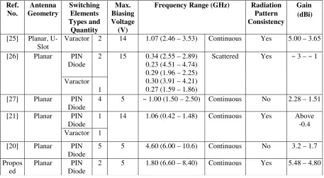
Table 3. Comparison of the proposed antenna with previously reported planar frequency reconfigurable antenna. Ref. No. Antenna Geometry Switching Elements Types and Quantity Max. Biasing Voltage (V)
Frequency Range (GHz) Radiation Pattern Consistency
Gain
[25] Planar, U-Slot
Varactor 2 14 1.07 (2.46 – 3.53) Continuous Yes 5.00 – 3.65
[26] Planar PIN Diode
2 15 0.34 (2.55 – 2.89) 0.23 (4.51 – 4.74) 0.29 (1.96 – 2.25) 0.30 (3.91 – 4.21) 0.27 (1.59 – 1.86)
Scattered Yes ~ 3 – ~ 1
Varactor 1 [27] Planar PIN
Diode
4 5 ~ 1.00 (1.50 – 2.50) Continuous No 2.28 – 1.51
[21] Planar PIN Diode
1 14 1.06 (0.42 – 1.48) Continuous Yes Above -0.4 Varactor 1
[20] Planar PIN Diode
5 5 4.60 (6.00 – 10.6) Continuous No 3.2 – 1.7
Propos ed
Planar PIN Diode
2 5 1.80 (6.60 – 8.40) Continuous Yes 5.48 – 4.80
(dBi)
relevant works is presented in Table 3. It is seen from the Table 3 that in most of the reported planar patch antennas, the frequency coverage range and antenna gain are less than the proposed antenna. In [21], a wide range of frequency coverage is reported; however, consistency of radiation patterns throughout the entire accessible range is not observed in the approach.
4. CONCLUSION
Shifts of resonant frequency using alterable meandered slot topology on an RMA are presented. An accessible range of 1.8 GHz is achieved through four reconfigurable bands. Use of meandered slots to shift the operating frequency helps in achieving the desired frequency agility without much compromising the consistency of the radiation pattern. In terms of radiation characteristics, the proposed antenna shows almost identical broadside radiation patterns with an average gain of 5.14 dBi. Degradations in the peak gain values are recorded towards the lower end of the operating range, which is mainly because of the increasing input impedance mismatch and limits the maximum attainable span of frequency. The presented approach offers a simple way of frequency reconfiguration without increasing antenna’s physical dimension. It is intended to keep the number of PIN diodes as low as possible to make the design simple and reduce the amount of losses introduced due to the lossy behavior of PIN diodes. Reduction in antenna patch dimension, simple reconfiguring circuitry and low operating voltage are the other features of the designed antenna. Enhancement of accessible frequency range without compromising the radiation characteristics as well as the gain is the scopes for further investigations. The proposed antenna could be potentially a suitable solution for hopping between closely spaced bands along with low cost and design simplicity as other vital parameters.
ACKNOWLEDGMENT
REFERENCES
1. Hinsz, L. and B. D. Braaten, “A frequency reconfigurable transmitter antenna with autonomous switching capabilities,”IEEE Transactions on Antennas and Propagation, Vol. 62, 3809–3813, 2014. 2. Petosa, A., “An overview of tuning techniques for frequency-agile antennas,” IEEE Antennas and
Propagation Magazine, Vol. 54, 271–296, 2012.
3. Ge, L. and K. M. Luk, “Frequency-reconfigurable low-profile circular monopolar patch antenna,”
IEEE Transactions on Antennas and Propagation, Vol. 62, 3443–3449, 2014.
4. Peroulis, D., K. Sarabandi, and L. P. B. Katehi, “Design of reconfigurable slot antennas,” IEEE Transactions on Antennas and Propagation, Vol. 53, 645–654, 2005.
5. Oh, S. S., Y. B. Jung, Y. R. Ju, and H. D. Park, “Frequency-tunable open-ring microstrip antenna using varactor,”2010 International Conference on Electromagnetics in Advanced Applications, 624– 626, 2010.
6. White, C. R. and G. M. Rebeiz, “Single- and dual-polarized tunable slot-ring antennas,” IEEE Transactions on Antennas and Propagation, Vol. 57, 19–26, 2009.
7. Cetiner, B. A., G. R. Crusats, L. Jofre, and N. Biyikli, “RF MEMS integrated frequency reconfigurable annular slot antenna,” IEEE Transactions on Antennas and Propagation, Vol. 58, 626–632, 2010.
8. Tawk, Y., J. Costantine, K. Avery, and C. G. Christodoulou, “Implementation of a cognitive radio front-end using rotatable controlled reconfigurable antennas,”IEEE Transactions on Antennas and Propagation, Vol. 59, 1773–1778, 2011.
9. Panagamuwa, C. J., A. Chauraya, and J. C. Vardaxoglou, “Frequency and beam reconfigurable antenna using photoconducting switches,” IEEE Transactions on Antennas and Propagation, Vol. 54, 449–454, 2006.
10. Anagnostou, D. E., Z. Guizhen, M. T. Chryssomallis, J. C. Lyke, G. E. Ponchak, J. Papapolymerou, et al., “Design, fabrication, and measurements of an RF-MEMS-based self-similar reconfigurable antenna,” IEEE Transactions on Antennas and Propagation, Vol. 54, 422–432, 2006.
11. Christodoulou, C. G., Y. Tawk, S. A. Lane, and S. R. Erwin, “Reconfigurable antennas for wireless and space applications,” Proceedings of the IEEE, Vol. 100, 2250–2261, 2012.
12. Erfani, E., J. Nourinia, C. Ghobadi, M. Niroo-Jazi, and T. A. Denidni, “Design and implementation of an integrated UWB/reconfigurable-slot antenna for cognitive radio applications,”IEEE Antennas and Wireless Propagation Letters, Vol. 11, 77–80, 2012.
13. Li, T., H. Zhai, X. Wang, L. Li, and C. Liang, “Frequency-reconfigurable bow-tie antenna for bluetooth, WiMAX, and WLAN applications,”IEEE Antennas and Wireless Propagation Letters, Vol. 14, 171–174, 2015.
14. Chunna, Z., Y. Songnan, H. K. Pan, A. E. Fathy, S. El-Ghazaly, and V. Nair, “Development of reconfigurable mini-nested patches antenna for universal wireless receiver using MEMS,” 2006 IEEE Antennas and Propagation Society International Symposium, 205–208, 2006.
15. Bhattacharjee, T., H. Jiang, and N. Behdad, “Fluidic beam steering in parasitically coupled patch antenna arrays,”Electronics Letters, Vol. 51, 1229–1231, 2015.
16. Weedon, W. H., W. J. Payne, and G. M. Rebeiz, “MEMS-switched reconfigurable antennas,”IEEE Antennas and Propagation Society International Symposium. 2001 Digest. Held in conjunction with: USNC/URSI National Radio Science Meeting (Cat. No.01CH37229), 654–657, Vol. 3, 2001. 17. Fan, Y. and Y. Rahmat-Samii, “Patch antennas with switchable slots (PASS) in wireless
communications: concepts, designs, and applications,”IEEE Antennas and Propagation Magazine, Vol. 47, 13–29, 2005.
18. Nazir, I., I. E. Rana, N. U. A. Mir, and K. Afreen, “Design and analysis of a frequency reconfigurable microstrip patch antenna switching between four frequency bands,” Progress In Electromagnetics Research C, Vol. 68, 179–191, 2016.
20. Pazin, L. and Y. Leviatan, “Reconfigurable slot antenna for switchable multiband operation in a wide frequency range,” IEEE Antennas and Wireless Propagation Letters, Vol. 12, 329–332, 2013. 21. Li, H., J. Xiong, Y. Yu, and S. He, “A simple compact reconfigurable slot antenna with a very wide tuning range,”IEEE Transactions on Antennas and Propagation, Vol. 58, 3725–3728, 2010. 22. Xiao, S., B.-Z. Wang, and X.-S. Yang, “A novel frequency-reconfigurable patch antenna,”
Microwave and Optical Technology Letters, Vol. 36, 295–297, 2003.
23. Oliveira, E. E. C., P. H. d. F. Silva, A. L. P. S. Campos, and A. G. d’Assuno, “Small-size quasi-fractal patch antenna using the Minkowski curve,” Microwave and Optical Technology Letters, Vol. 52, 805–809, 2010.
24. Agrawal, A. K. and K. J. Vinoy, “Microstrip coupled line bandpass filter using quasi Minkowski fractal shape for suppression of the second harmonic,”2015 IEEE MTT-S International Microwave and RF Conference (IMaRC), 412–415, 2015.
25. Ren, Z., W.-T. Li, L. Xu, and X.-W. Shi, “A compact frequency reconfigurable unequal U-slot antenna with a wide tunability range,” Progress In Electromagnetics Research Letters, Vol. 39, 9–16, 2013.
26. Koley, S. and D. Mitra, “A compact dual-band reconfigurable open-end slot antenna for cognitive radio front end system,” Progress In Electromagnetics Research C, Vol. 58, 33–41, 2015.
27. Sharma, S. and C. C. Tripathi, “Frequency reconfigurable U-slot antenna for SDR application,”