Compact Patch Antenna on Structurally Modified
Magnetodielectric Substrate
Arunav Phukan1, Kunal Borah2, and Nidhi S. Bhattacharyya1, *
Abstract—Magnetodielectric substrate gives a new dimension for reducing the size of the planar antennas. In this article, the patch size is reduced by taking a substrate with nano-sized nickel ferrite inclusions in LDPE polymer matrix. The antenna is made to operate in X and Ku bands by engraving T slots along the resonant length of the patch. Structural modification of the substrate geometry as a step profile is incorporated along the slotted patch edges to enhance performance. The T-slots, along both the resonating lengths with the magnetodielectric stepped substrate show four resonant frequencies in both X- and Ku-bands withS11<−15 dB and a maximum−10 dB bandwidth of 22.4%.
A miniaturization factor of 2.97 is obtained.
1. INTRODUCTION
Integration of more communication standards in one microwave wireless device has created demand on developing compact, low-cost, and robust multi-band microwave components. Microstrip patch antennas (MPA) are an important transreceiving transducer in microwave devices, and low profile of this component is desirable. Miniaturization in MPA, denoted by factor,n, is given asn=√(εrμr), where, εr is the complex permittivity andμr the complex permeability of the substrate [1]. Major shortfalls
of using high εr substrates are lowering of radiation efficiency, pattern degradation (due to excitation of surface waves) and lowering of impedance bandwidth [2, 3]. Miniaturization can also be achieved by modifying the other parameter μr. Bulk ferrites, generally, have high saturation magnetization and dispersive magnetic losses [4–6] and needs strong external dc-bias fields to alter its permeability property [7], making it unsuitable for compact applications. Further, shift of operational frequency of antennas on ferrite substrates on application of external bias [8, 9] causes difficulty in integrating it with other systems. Lately, artificial magnetodielectric substrates are used to overcome issues of high loss in ferrites. Non-magnetic materials can be engineered with embedded circuits to achieve magnetic permeability [10]. However, the process of developing engineered artificial magnetic materials is complex [11–13]. Nano-sized ferrites are reported to have low saturation magnetizations and low eddy current losses [14, 15]. Composites made using nano ferrite inclusion in polymers can result in natural magnetodielectric materials with low magnetic losses. εr and μr of the composite can be altered by varying the amount of the inclusion to achieve the desired performance [16].
The work carried out is focussed on developing a single patch miniaturized antenna for operation in X- and Ku-bands, primarily used in satellite, radar, space and terrestrial communications. A magnetodielectric composite with natural nano ferrite inclusions is developed as the substrate material for microstrip patch antenna miniaturization.
Modern wireless communications impose the need for design and development of efficient antenna elements used in systems that will operate in contemporary multi-service urban environments, in which
Received 11 January 2016, Accepted 16 April 2016, Scheduled 6 May 2016
* Corresponding author: Nidhi Saxena Bhattacharyya ([email protected]).
1 Microwave Engineering Lab, Department of Physics, Tezpur University, India. 2 Department of Physics, North Eastern Regional
several different networks coexist and interoperate. These antennas should necessarily function in multi-band modes [17]. Modifying the patch using slots, stubs and loading is a common technique for achieving multi-frequency operation [18]. However, stubs and loading techniques typically increase the antenna size, either in the antenna plane or along its thickness. Slots can enhance performance without increasing the dimension of the patch. L-, U-, E-, T-, H-shaped slots [19–23] are common slot geometries reported in literature. A T-slot, as compared to others, is easy to incorporate onto the rectangular patch. In addition, the various sections of the T-geometry provides the flexibility to optimize the structure as per the requirement. In the current work, T-slots are engraved along the resonating length as shown in Fig. 2 and their performance studied.
The authors in their earlier work [24] modified the structure of a substrate in the form of a stepped profile to obtain multifrequency resonance with improved performance for a simple rectangular patch. The stepped substrate geometry studied reduces the surface waves and enhances the return loss characteristics. The performance of the T-slotted patch is studied with stepped structure of the substrate. Similar studies are carried out using a standard dielectric substrateFR4 (εr-4.3, tanδ-0.021), to test the feasibility of the structure.
2. SYNTHESIS AND STUDY OF MAGNETODIELECTRIC MATERIAL
In our current study, particulate composites with nickel ferrites (NiFe2O4) nano-magnetic inclusions
in a low density poly ethylene (LDPE) polymer matrix is developed as the substrate for the antenna. Nickel ferrite (NiFe2O4) is chosen as it is known to handle high microwave powers without affecting
its magnetic properties as its Curie temperature is ∼500◦C [25]. The polymer base of the composite system gives shape and flexibility to the substrate with reduced weight. The mechanical properties of LDPE are those between rigid materials such as polyester and limped polymers as vinyls. Moreover, it has low dielectric loss at microwave frequencies and is thus a suitable host matrix for microwave substrate applications.
NiFe2O4 crystallites are synthesized by co-precipitation technique using nickel (II) nitrate
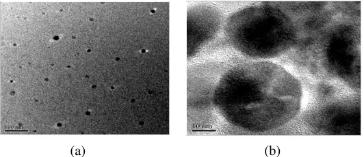
hexahydrate (98% pure), iron (III) nitrate nonahydrate (98% pure) as precursors in stoichiometric amounts described in the previous work done by the authors [25]. X-ray diffraction studies show the crystalline size to be ∼12 nm. The particle size is determined using transmission electron microscopy (TEM) and found to be ∼ 30 nm. The image is shown in Fig. 1. Nano-sized NiFe2O4 crystallites
are dispersed in low density polyethylene (LDPE) to develop magnetodielectric substrate with varying volume fraction. Volume fraction (VF) of the nickel ferrite beyond 5% makes the composite brittle and fragile, and the sinkage of ferrite inclusions occurs as the host polymer reaches the percolation limit. The magnetodielectric materials are morphologically tested for dispersion uniformity by scanning electron microscopy (SEM). Magnetic characterizations are carried out using vibrating sample magnetometry and microwave characterizations using Nicolson-Ross techniques [26]. The 5% VF nickel ferrite/LDPE substrate (ε = 7.385, ε = 9.9×10⁻³ at 10 GHz and μ= 1.1998, μ= 0.88 at 9.86 GHz and 4πMs as 1.87 emu/g) is chosen for showing the best performance in terms of S11and −10 dB bandwidth. In the
study to follow, the 5% VF nickel ferrite/LDPE substrate is termed as ‘magnetodielectric’, while the standardFR4 substrate is termed as ‘dielectric’.
(a) (b)
Figure 1. Transmission electron microscope image of NiFe2O4 nanoparticles with scale factor of (a)
3. DESIGN AND FABRICATION OF T SLOTTED STEP PROFILE ANTENNA
A simple rectangular patch is designed using standard design equations based on transmission line model (TLM) [27]. The length (L) and width (W) of the patch resonating at 9 GHz obtained for a substrate height, H = 2 mm are tabulated in Table 1.
Table 1. Simple rectangular patch dimension at 9 GHz using TLM.
Substrate Material Permittvityε Permeabilityμ
Length (L) (mm)
Width (W) (mm) 5% VF nickel
ferrite/LDPE (magnetodielectric)
7.385 1.198 5.34 8.20
FR4 substrate
(dielectric) 4.4 1 7.1 10.2
The miniaturization factor, n, can be calculated from the equation, n =√(εrμr) [1] where εr is the real part of complex permittivity and μr the real part of complex permeability of the substrate. For magnetodielectric substrate with εr = 7.385, μr = 1.198, nNF/LDPE = 2.97, while for standard dielectric substrate with εr = 4.4, μr = 1, nFR4 = 2.09. Thus, the miniaturization factor of the
patch on the magnetodielectric substrate to that on the dielectric substrate is equal to 1.42, i.e., nNF/LDPE/nFR4= 1.42.
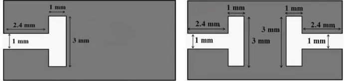
The dimensions of the T-slots are obtained by optimizing the width and length of the slots for the antenna using CST microwave studio software. T-slots are placed symmetrically at the center of the resonating length. Two patch configurations are studied with T-slot (i) one of the non-radiating edges and (ii) both the non-radiating edges, referred as single T-slot and double T-slots, respectively. The schematic of the designed T-slot with dimensions is given in Fig. 2.
Figure 2. Single T slot and double T slot dimensional schematic.
In a previous work done by the authors in [24], a stepped profile was introduced in substrate geometry to enhance antenna performance. The substrate was laterally removed in vicinity to the radiating edge of the patch. Schematic diagrams of the step profile are shown in Figs. 3(a), (b) and (c). The studies were conducted by varying the step riser height, h, and step tread length, L+ 2w. A parametric analysis was conducted with an equivalent circuit model proposed in the same paper. Step configuration with h = 1.5 mm and w = 1 mm showed the best performance in terms of the S11
characteristics and multiresonance. The same step configuration was employed in this work for both the magnetodielectric and dielectric substrates.
(a)
(c)
(b)
Figure 3. Schematic of antenna profile (a) before removing the lateral portion of the substrate, (b) with the stepped substrate, (c) showing detailed side view of the step.
(a)(i) (a)(ii)
(b)(i) (b)(ii)
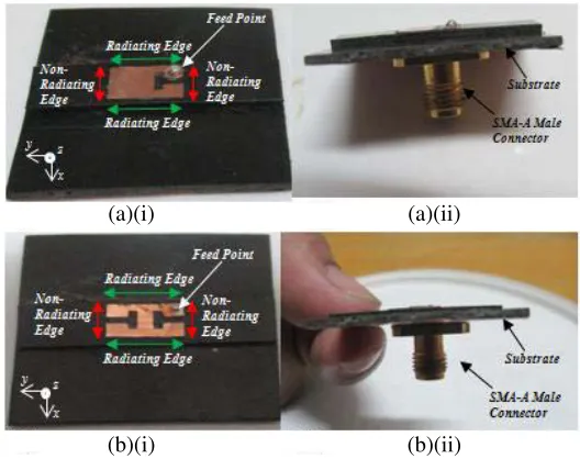
Figure 4. Photographs of the (i) top view, (ii) side view of (a) single T-slot antenna stepped magnetodielectric substrate and (b) double T-slot antenna on stepped magnetodielectric substrate.
blending. The homogenous viscous composite is slowly poured into the mould and allowed to cool gradually at room temperature.
The fabrication of a copper patch on the magnetodielectric composite substrate is performed by rolling technique. The substrate is cleaned with acetone to remove oil and grime from the surface. The substrate is dried at 30◦C in a vacuum oven. A copper adhesive tape of thickness 0.03 mm is used to fabricate the patch and the ground plane of the rectangular microstrip patch antenna. The designed artwork, of the patch, as shown in Fig. 2, is transferred to the adhesive copper tape using hot press technique. The copper tape with the artwork printed on it is then dipped into an etching solution for sufficient time until the etching process is completed. The etched tape is washed with double distilled water and then dried to remove any traces of the etchant. The tape, after etching, is then rolled over the substrate at a pressure of 6 torr for two hours. The fabrication on the stepped dielectric is done by a similar technique. In this case, copper laminated dielectric stepped substrate is used. The patch artwork is first transferred onto the copper laminated substrate using hot press technique, which is then etched in an etching solution.
Figures 4(a)(i) & 4(b)(i) and Figs. 5(a)(i) & 5(b)(i) show photographs of the fabricated patch antennas on both the stepped magnetodielectric and dielectric substrates.
The MPA is excited by coaxial feeding technique using a single miniature type-A female coaxial connector having an impedance of 50 ohms, at 1 mm from one of the radiating edge and 1.5 mm from the non radiating edge, as shown in Figs. 4(a)(ii) & 4(b)(ii) and Figs. 5(a)(ii) & 5(b)(ii).
(a)(i) (a)(ii)
(b)(i) (b)(ii)
Figure 5. Photographs of the (i) top view, (ii) side view of (a) single T-slot antenna stepped dielectric substrate and (b) double T-slot antenna on stepped dielectric substrate.
4. PERFORMANCE STUDIES OF THE T SLOTTED ANTENNA
Return loss measurements are carried out over the range 1 GHz to 20 GHz using Agilent PNA series vector network analyzer (VNA) E8362C. The S11 plots for the single slot antenna and double
T-slot antenna on the magnetodielectric substrate for both flat and stepped configurations are shown in Figs. 6(a) and 6(b), respectively. Figs. 7(a) and 7(b) show S11 for the same slotted configurations on
the dielectric substrate. The results are summarized in Table 2.
The antenna on the magnetodielectric substrate with the flat profile exhibits two frequency notches for a single T configuration, one at 8.89 GHz (S11 = −24.1 dB) and the other at 9.5 GHz
(S11=−15.3 dB). Double T configuration shows two prominent notches at 4.54 GHz (S11=−16.3 dB)
and at 10.5 GHz (S11 = −29.1 dB). Flat profile antenna on the dielectric substrate shows frequency
notches at 9.45 GHz (S11 = −24.43 dB) and at 13.85 GHz (S11 = −25.34 dB) for single T and at
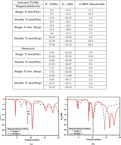
Table 2. Table for theS11 plot results.
Antenna Profile
Fr(GHz) S11 (dB) −10dB% Bandwidth Magnetodielectric
Single T-slot(Flat) 8.8 −24.0 11.5
9.5 −15.3 10.7
Double T-slot(Flat) 4.54 −16.33 4.6
10.5 −29.1 5.8
Single T-slot (Step) 10.2 −33.5 9.9
14.4 −29.6 8.9
Double T-slot(Step)
8.6 −21.2 1.8
10.31 −18.34 4.0
16.29 −28.43 22.4
17.86 −25.42 20.4
Dielectric
Single T-slot(Flat) 9.45 −24.43 1.9
13.85 −25.34 15.0
Double T-slot(Flat) 6.69 −25.08 2.5
13.53 −30.67 9.6
Single T-slot (Step)
7.11 −15.28 5.9
7.34 −33.02 5.7
13.04 −14.98 8.4
Double T-slot(Step)
6.80 −36.11 2.5
12.17 −16.11 5.0
14.16 −30.44 6.3
(a) (b)
Figure 6. S11plots for the T-slot configuration on (a) flat, (b) stepped magnetodielectric substrate.
T patch on the magnetodielectric substrate shows −10 dB impedance bandwidth more than 10% for both the lower and higher resonant frequencies, while the dielectric substrate shows only for the higher resonant frequency.
(a) (b)
Figure 7. S11plots for the T-slot configuration on (a) flat, (b) stepped dielectric substrate.
Figure 8. Radiation pattern (E-field &H-field) plots for magnetodielectric substrate (inset-directivities in dBi).
of the antenna compared to flat profile geometry. The stepped profile with double T configurations on magnetodielectric substrate shows the best performance with four frequency notches at 8.6 GHz, 10.31 GHz, 16.29 GHz and 17.86 GHz with S11 values, −21.2 dB, −18.34 dB, −28.43 dB, −25.42 dB,
respectively. The impedance bandwidth also shows substantial increase to 22.4% for frequency of 16.29 GHz and 20.4% for frequency 17.86 GHz. An improvement of performance in stepped single T-profile is also observed.
Radiation pattern measurements are carried out using an automated system which includes a signal generator Agilent MXG-N5183A as source, Agilent U2000A USB power sensor, and a PC controlled turn table. The patterns are plotted at the frequency showing maximum S11 in X-band. Fig. 8 shows
Figure 9. Radiation pattern (E-field & H-field) plots for dielectric FR4 substrate (inset-directivities in dBi).
(c) (b)
(a)
The respective directivites are also mentioned in the inset of the plots. The stepped structure on magnetodielectric substrate shows an increase in directivity.
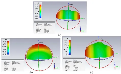
A simulation study using CST Microwave Studio is carried out for gain pattern analysis of the stepped profile double T configuration on the magnetodielectric substrate and on the dielectric substrate. The simulated patterns are shown in Figs. 10(a) and (b). A gain of 9.7 dB is observed for patch on the magnetodielectric substrate while patch on the dielectric substrate shows a gain of 2.9 dB.
Simulated study is also carried out for the same patch configuration on a standard laminated ROGERS TMM 10 substrate (ε = 9.2 andμ = 1) having approximately similar miniaturization factor as the magnetodielectric substrate. As shown in Fig. 10(c), a gain of 7.9 dB is observed.
5. CONCLUSION
A T-slotted patch is known to give multi-frequency resonance, but the performance is confined to the same band. Introducing step in the substrate profile reduces the surface wave of the antenna thus enhancing its performance. Encompassing T-slots and stepping geometry on the dielectric substrate shows multiband performance. Interestingly, double T stepped configuration on the dielectric substrate shows frequency notches in C-, X- and Ku-bands.
Incorporating the same T-slotted stepped structure on a magnetodielectric substrate shows multiple frequency notches in X- and Ku-bands. The miniaturization factor of the antenna on magnetodielectric substrate to that on the dielectric substrate is found to be 1.42. Bandwidth enhancement is also observed for antennas on magnetodielectric substrate. The double T slotted stepped profile antenna on magnetodielectric substrate proves to be better than other configurations in terms of the S11
and −10 dB impedance bandwidth. Removal of the substrate in vicinity of the patch reduces the overall volume and weight of the antenna. Simulated gain analyses show that the gain is higher for antenna on magnetodielectric substrate rather than on dielectric substrate having same miniaturization factor. Magnetodielectric substrate gives an interesting option of reducing the size, enhancing the impedance bandwidth and increasing the gain of the antenna. Compared to a flat geometry, the stepped configuration shows improvedS11characteristics. However, increase of magnetic inclusions and thereby
the magnetic property of the substrate is limited by percolation limit of the polymer matrix. A polymer matrix with a higher percolation limit may solve this problem.
REFERENCES
1. Petrov, R. V., A. S. Tatarenko, G. Srinivasan, and J. V. Mantese, “Antenna miniaturization with ferrite ferroelectric composites,” Microw. Opt. Technol. Lett., Vol. 50, No. 12, 3154–3157, 2008. 2. Wheeler, H. A., “Fundamental limits of small antennas,”Proceedings of the I.R.E. (IEEE), 1479–
1484, December 1947.
3. Fujimoto, K., A. Henderson, K. Hirasawa, and J. R. James, Small Antennas, John Wiley & Sons Inc., 1987.
4. Luo, H. Y., Z. X. Yue, and J. Zhou, “Synthesis and high-frequency magnetic properties of sol-Gel derived Ni Zn ferrite forsterite composites,” Journal of Magnetism and Magnetic Materials, Vol. 210, 104–108, 2000.
5. Nejati, K. and R. Zabihi, “Preparation and magnetic properties of nano size nickel ferrite particles using hydrothermal method,”Chemistry Central Journal, Vol. 6, 23, 2012.
6. Singh, S., N. K. Ralhan, R. K. Kotnala, and K. C. Verma, “Nanosize dependent electrical and magnetic properties of NiFe2O4 ferrite,” Indian Journal of Pure & Applied Physics, Vol. 50, 739–
743, 2012.
7. Vollinger, C., F. Caspers, and E. Jensen, “The effect of 2-directional magnetic biasing used for tuning of a ferrite-loaded re-entrant cavity,” IEEE Trans. Nucl. Sci., Vol. 60, No. 3, 2170–2174, 2013.
9. Yang, G. M., X. Xing, O. Obi, A. Daigle, M. Liu, S. Stoute, K. Naishadham, and N. X. Sun, “Loading effects of self-biased magnetic films on patch antennas with substrate/superstrate sandwich structure,”Microwaves, Antennas & Propagation, IET,Vol. 4, No. 9, 1172–1181, 2010. 10. Kostin, M. V. and V. V. Shevchenko, “Artificial magnetics based on double circular elements,”
Proc. Bianisotropics’94, 49–56, P´erigueux, France, 1994.
11. K¨arkk¨ainen, M. and P. Ikonen, “Patch antenna with stacked split-ring resonators as artificial magneto-dielectric substrate,”Microwave Opt. Technol. Lett., Vol. 46, No. 6, 554–556, 2005. 12. Buell, K., H. Mosallaei, and K. Sarabandi, “A substrate for small patch antennas providing tunable
miniaturization factors,”IEEE Trans. Microw. Theory Tech., Vol. 54, 135–145, 2006.
13. Ikonen, P., S. Maslovski, C. Simovski, and S. Tretyakov, “On artificial magneto-dielectric loading for improving the impedance bandwidth properties of microstrip antennas,”IEEE Trans. Antennas Propag., Vol. 54, No. 6, 1654–1662, 2006.
14. Uskokovi´c, V., M. Drofenik, and I. Ban, “The characterization of nanosized nickel-zinc ferrites synthesized within reverse micelles of CTAB/1 — Hexanol/water microemulsion,” Journal of Magnetism and Magnetic Materials, Vol. 284, 294–302, 2004.
15. Son, S., M. Taheri, E. Carpenter, V. G. Harris, and M. E. McHenry, “Synthesis of ferrite and nickel ferrite nanoparticles using radio-frequency thermal plasma torch,” Journal of Applied Physics, Vol. 91, No. 10, 2002.
16. Mazaleyrat, F. and L. K. Varga, “Ferromagnetic nanocomposites,” J. Magnetism and Magnetic Materials, Vol. 2, 215–216, 2000.
17. Ahmed, E. S., “Multiband CPW-fed rectangular ring microstrip antnna design for wireless communications,”2011 IEEE Jordan Conference on Applied electrical Engineering and Computing Technologies (AEECT), 978-1-4577-1084/11 c2011 IEEE, 2011.
18. Polivka, M., M. Drahovzal, and M. Mazanek, “Synthesis of dual-band broadside radiated microstrip patch antenna operating with TE and TM modes,” Proceedings of IEEE Antennas Propagation Society International Symposium, Vol. 1, 245–248, 2004.
19. Song, K., Y.-Z. Yin, S.-T. Fan, and B. Chen, “Compact open-ended L-shaped slot antenna with asymmetrical rectangular patch for UWB applications,” Progress In Electromagnetics Research C, Vol. 19, 235–243, 2011.
20. Yang, Z., H. Zhang, N. Zhou, and B. Wu, “A dual band U-shaped slot antenna for WLAN and WiMAX applications,” PIERS Proceedings, 1486–1489, Guangzhou, China, Aug. 25–28, 2014. 21. Ang, B. K. and B. K. Chung, “A wideband E-shaped microstrip patch antenna for 5–6 GHz wireless
communications,”Progress In Electromagnetics Research, Vol. 75, 397–407, 2007.
22. Ni, T., Y.-C. Jiao, Z.-B. Weng, and L. Zhang, “T-shaped antenna loading t-shaped slots for multiple band operation,” Progress In Electromagnetics Research C, Vol. 53, 45–53, 2014.
23. Lee, C. I., W. C. Lin, Y. T. Lin, and Y. T. Lee, “A novel H-shaped slot-coupled antenna for the integration of power amplifier,” PIERS Proceedings, 385–389, Cambridge, USA, Jul. 5–8, 2010. 24. Borah, K., A. Phukan, S. Bhattacharyya, and N. S. Bhattacharyya, “Design of light weight
microstrip patch antenna on dielectric and magnetodielectric substrate for broadband applications in X-band,”Progress In Electromagnetics Research B, Vol. 60, 157–168, 2014.
25. Borah, K. and N. S. Bhattacharyya, “Magnetodielectric composite with NiFe2O4 inclusions as
substrates for microstrip antennas,” IEEE Transactions on Dielectric and Electrical Insulation, Vol. 19, No. 5, 1825–1832, 2012.