Compact EBG Structures for Reduction of Mutual Coupling
in Patch Antenna MIMO Arrays
Mohammad Naser-Moghadasi1, Rahele Ahmadian2, Zahra Mansouri3, *, Ferdows B. Zarrabi4, and Maryam Rahimi2
Abstract—Electromagnetic band gap (EBG) structures are usually realized by periodic arrangement of dielectric materials. These periodic structures can help in the reduction of mutual coupling in array antennas. In this paper a new arrangement of EBG structures is presented for reducing mutual coupling between patch antenna MIMO arrays. The patch antennas operate at 5.35 GHz which is defined for wireless application. Here 2×5 EBG structures are used to reduce mutual coupling more than 20 dB. The total size of the antenna is 36 mm×68 mm×1.6 mm. So it is more compact in than pervious research. Experimental results of return loss and antenna pattern have been presented for 5.4 GHz and compared with HFSS simulation results. Also the EBG structures have been designed with numerical modeling and dispersion diagram. New EBG model is compared with conventional EBG model, and equivalent circuit model is given for new structure.
1. INTRODUCTION
Recently, in next-generation wireless communication systems, there is high demand for high data transfer rate and fast access with best quality for cellar connection by MIMO (multi-input-multi-output) communication [1]. In the last two decades, different protocols have been defined by IEEE to improve wireless access for voice communication in cellar phone such as GSM 900 or GSM 1800, WLAN for high rate data communication in narrow band, UWB system such as IEEE 802.11a for 5.15–5.825 GHz and FCC in 3.1–10.6 GHz UWB range [2]. Microstrip antenna is a popular type of antenna for its good features such as planar structure, low cost, easy fabrication, ability to use in integrated circuits and compact devices. Microstrip antennas are appropriate for array form antenna and MIMO systems, and it has been noticed because of easy feed [3]. In some applications, size reduction of microstrip antenna is needed, and some methods are introduced for this aim [3]. One way is to use metamaterial structures such as CRLH and EBG to reduce the size of the microstrip antenna [2–4]. Metamaterials have some unusual properties such as anti-parallel phase, group velocities, and negative reflection index. Metamaterials are known as artificial structures and do not exist in natural situation [5].
In metamaterial structures, electric field, magnetic field and wave vector follow left-hand rule, so they are called left-handed materials (LHM). They have negative permittivity and permeability, so they are also called double negative (DNG). Thus, in some structures only one of them is negative. Metamaterials make it possible to design a miniaturized, multi-band antenna, filter or other microwave devices [5].
EBG structures are defined as a kind of artificial magnetic conductor (AMC) that prevent/assist the propagation of electromagnetic waves in a specified band of frequency for all incident angles and
Received 16 August 2014, Accepted 15 September 2014, Scheduled 22 September 2014 * Corresponding author: Zahra Mansouri ([email protected]).
1 Department of Electrical and Computer Engineering, Sciences and Research Branch, Islamic Azad University, Tehran, Iran. 2Young
using metamaterial structure in ground plane by Salehi and Tavakoli [15].
Coupling between the microstrip antenna arrays is the essential problem that always exists. To solve the problem, metamaterial development is used in a rectangular patch antenna array substrate in order to reduce coupling between array antennas [16–18]. EBG structure is the most popular element, which consists of metal or dielectric periodic structures, and shows characteristics of pass or band-stop [19] and makes isolation between components [20]. They can be used in other applications such as to reduce coupling between two parallel plate waveguides up to 20 dB and suppression of surface wave between other structures, and it has been noticed by Mohajer-Iravani et al. to reduce coupling of patch and aperture [21]. Various forms of planar EBGs, such as mushrooms and fractal shapes, are introduced to expand the bandwidth, phase characteristics and improvement of gain. Also studies on equivalent circuits have been performed to modify bandwidth [22–24]. As described in [22] because the surface wave propagate along the E-plane direction, EBG structure has strong effect in reducing the surface wave inE-plane condition, and through it, the coupling between antennas will be reduced. On the other hand, forH-plane state EBG cells have a week role in reducing mutual coupling.
Coupling coefficient is calculated by the following equation [25]:
|C|2= |S21| 2
(1− |S11|2)×(1− |S22|2)
(1)
In this paper, a novel effective EBG structure is suggested to reduce mutual coupling between patch antenna arrays. The patch antennas operate at 5.35 GHz which is attractive frequency for wireless applications. We have used 2×5 EBG structures to reduce mutual coupling more than 20 dB. Here cells in a row are joint to improve the mutual coupling. ZOR dispersion diagram is used for conventional EBG, and then the effect of the slots is studied. The E-plane and H-plane patch coupling is studied with prototype EBG and surface current distribution with and without EBG structure emphasizes the effect of the EBG on mutual coupling.
2. EBG MODELING AND NUMERICAL METHOD
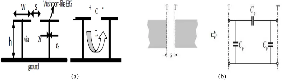
Figure 1(a) shows how inductance (L) and capacitance (C) are determined by conventional EBG structure. Resonant behavior is used to explain the features of the EBG band gap structure. This model is not very accurate because of simple approximation of C and L [26]. Parameters of the EBG structure in Fig. 1(a) are patch widthW, gap widthS, substrate thicknessh, via radiusr and dielectric constant εr. When the periodic length of structure (W +S) is small compared to the wavelength, the mechanism of EBG structure can be explained by a model of the compact LC elements. As shown in Fig. 1, equivalent capacitor is obtained by the gap between the patches and current through the adjacent patches [26]. Fig. 1(b) demonstrates microstrip gap structure that includes a coupling seriesand parallel capacitor between the patch and the ground plane, respectively. The value of this capacitor can be calculated by [28–29].
Impedance and resonant frequency of a parallelLC circuit can be obtained as follows:
Z = jωL
1−ω2LC ω0 = 1
√
LC (2)
For a simple patch, the edge capacity of a narrow gap is calculated as [27]:
C = W ε0(1 +εr)
π cosh
−1
W +S S
(a) (b)
Figure 1. EBG structure and gap. (a) Model for the compact LC. (b) Microstrip gap structure and its equivalent circuit.
L = μh (4)
According to the following equations, the parameters that affect the value of the series capacitors are length (s) and gap width (w). The series capacitor gets larger with smaller gap length.
Cp = 0.5Ce (5)
Cp = 0.5Ce (6)
Cg = 0.5Co−0.25Ce (7)
Co
W (pF/m) =
εr 9.6
0.8 s
W
mo
exp (Ko) (8)
Ce W pF m = 12 εr 9.6
0.9 s
W
me
exp exp (Ke) (9)
⎧ ⎪ ⎪ ⎨ ⎪ ⎪ ⎩
mo= W
h
0.619 log log
W h
−0.3853
Ko = 4.26−1.453 log
W h
for 0.1≤s/W ≤1.0 (10)
⎧ ⎪ ⎪ ⎨ ⎪ ⎪ ⎩
me= 0.8675, Ke = 2.043
W h
0.12
for 0.1≤s/W ≤0.3
me= 1.565
(W/h)0.16 −1, Ke= 1.97− 0.03
W/h for 0.3≤s/W ≤1.0
(11)
Figure 2(a) shows the comparison of the dispersion diagram between the simple patch and designed structure by using the full wave simulation. In a simple patch structure, the zero order resonance (ZOR) occurs at 5.8 GHz. With numerical calculations the inductance is 2µH, and capacitance is 0.34 pF, so the resonance is achieved at 5.98 GHz. In modified structure, the ZOR frequency is decreased to 5 GHz. In the second model, the inductance is 2µH, and series capacitance is increased by gap structure to 0.5 pF, so the calculated resonance is at 5.02 GHz.
Figure 2(b) shows the final prototype EBG equivalent circuit. Some equivalent circuit parameters have been neglected here. Lp and Cg are calculated by Equations (4) and (3), respectively. With this calculation the value of Cg is 0.17 Pf. For calculation of Cs Equations (5) to (11) have been used, and
Cs is obtained, about 0.46 Pf. So total capacitance is about 0.57 Pf.
3. SIMULATION AND EXPERIMENTAL RESULT
(a) (b)
Figure 2. Unit cells modeling. (a) Dispersion diagram of conventional EBG and new designed unit cell. (b) Equivalent circuit model for new designed EBG unit cell.
(a) (b)
Figure 3. Patches array antenna with EBG structure. (a) Simulation and dimensions. (b) Fabricated antenna.
(a) (b)
distance between them is 34 mm. The designed antenna is fabricated on a low cost FR-4 substrate where the permittivity is 4.4, and dielectric loss tangent is 0.02. It is fed by 50 Ω coaxial probe, and the bandwidth of antenna is 3%. Fig. 3 shows patches array antenna with a EBG structures. The antennas are in E-plane coupling state. The cell size of periodic structure is 6.4 mm×6.4 mm, and Vias radius is 0.5 mm. The total size of antenna is 36 mm×68 mm×1.6 mm. All dimensions are presented in Table 1 with details.
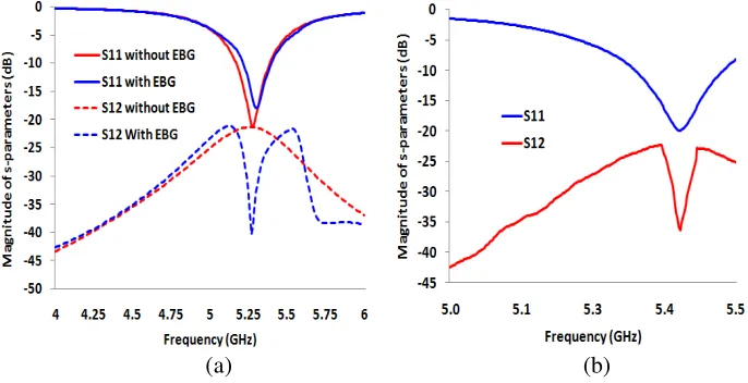
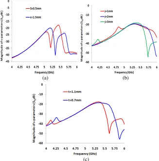
First resonance frequency of modified EBG cell is about 5 GHz, which is coincided with resonance of the patch. Fig. 4(a) shows the simulation results ofS parameters of array antenna with and without EBG structure. Mutual coupling level is about −22 dB for a simple array and −43 dB for the array with EBG structure. Obviously,S21is reduced more than 20 dB, by using the EBG structure. Fig. 4(b) shows experimental results for prototype arrangement with HP8722ES network analyzer. The prototype antenna has been modified for 5.35 GHz. In experimental result, S21is reduced to−36.3 dB. The effect of s,j andt onS12 in parametric form is studied as shown in Fig. 5.
Figure 5(a) shows the effect of change insto 0.5 mm and 1.5 mm. For lower s,S12 is reduced, and when it is increased, the frequency is shifted to higher frequency, but these changes are not effective, and less than 100 MHz shift is visible.
Figure 5(b) shows the effect of change in j for 1 mm, 2 mm and 3 mm. By increasing this gap the frequency is reduced. Fig. 5(c) shows the effect of change in t for 0.7 mm and 1.1 mm. By increasing this gap, the frequency is reduced. So t and j are most important parameters which will affect EBG characteristic.
The dispersion diagram of EBG unit cell shows that the frequency changes have similar behavior to that in S12 of the antenna, but a little shift is visible in Fig. 2 and Fig. 6 dispersion diagrams in
(a) (b)
(c)
(a)
(b) (c)
Figure 6. Dispersion diagram. (a) Change ins. (b) Change in j. (c) Change in t.
Table 1. Geometry dimensions of antenna and EBG.
parameter mm
a 36
b 78
c 14.4
d 12.6
e 6.4
f 13.4
g 0.6
h 21.4
i 4
j 4.4
k 7
s 1
(a) (b)
(c) (d)
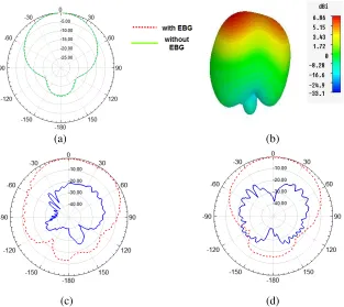
Figure 7. The pattern of antenna with and without EBG (a) simulation of the E-plane in presence and absence of EBG. (b) Gain and 3D pattern of antenna in 5.3 GHz. (c) The experimental result for
E-plane. (d) The experimental result for H-plane (co-polarization is shown with dashes).
(a) (b)
Figure 8. (a) The antenna structure in H-plane coupling. (b) s parameters of antenna with and without EBG.
The E-plane patterns of the antenna with absence and presence of EBG are demonstrated in Fig. 7(a) at 5.3 GHz. Here the comparison between prototype structure for conventional arrangement and that by applying EBG structure is presented, and as shown in Fig. 7(a) the EBG structure does not affect antenna pattern. Fig. 7(b) shows 3D pattern of the antenna at 5.3 GHz, antenna gain and simulation result around 6.86 dBi. Fig. 7(c) and Fig. 8(d) show the final structure’s (E-plane and
(a) (b)
Figure 9. Surface current distribution with and without EBG structure. (a) Patch array with EBG. (b) Patch array without EBG.
Figure 10. Antenna efficiency in presence and absence of EBG Cells.
Table 2. Comparison between presented design and previous researches.
Frequency range Mutual coupling Size
Our design 5.4 GHz 20 dB 68×36×1.6
Ref. [10] 5.9 GHz 18.28 dB 80×60×1.35
Ref. [11] 5 GHz 19 dB Not given
Ref. [12] 5.85 GHz 25.3 dB 100×50×2
Ref. [13] 5.75 GHz 14 dB 78×78×2.54
It is obvious that in H-plane coupling, EBG structure has no effect on reducing mutual coupling for this structure. Fig. 9 shows surface current distribution with and without EBG structure. Obviously, our EBG absorber has limited the current distribution on the antenna surface and mutual coupling of antenna at the resonant frequency. The EBG has restricted the surface field in array structure. The antenna current is reduced from 8.5 A/m to around 3.9 A/m in the presence of EBG, so the coupling current is reduced more than 50%.
cells the antenna efficiency is around 65% at 5.3 to 5.4 GHz, and when EBG cells are placed between antennas, antenna efficiency is reduced to 53% at 5.3–5.4 GHz.
Previously, different models of EBG have been used to decrease the mutual coupling between patch antennas in WLAN frequency at around 5 GHz. Table 2 represents the comparison between current structure and some pervious designs. The prototype structure’s size has been reduced about 20–40% in comparison to similar pervious researches.
4. CONCLUSIONS
In this paper, a novel effective EBG structure is suggested to reduce mutual coupling between patch antenna arrays. The patch antennas operate at 5.35 GHz which is attractive frequency for wireless applications. We have used 2×5 EBG structures to reduce mutual coupling more than 20 dB. The EBG cells capacitance and inductance have been calculated by numerical methods. S12 parameters are compared with dispersion diagram results. In addition, the simulation results are compared with experimental ones. Return loss and surface current in presence and absence of EBG cells have been compared by full wave simulations. The coupling current is reduced more than 50%, and the prototype structure size has been reduced around 20–40% in comparison to pervious researches.
REFERENCES
1. Yu, X., L. Wang, H.-G. Wang, X. Wu, and Y.-H. Shang, “A novel multiport matching method for maximum capacity of an indoor MIMO system,”Progress In Electromagnetics Research, Vol. 130, 67–84, 2012.
2. Rahimi, M., F. B. Zarrabi, R. Ahmadian, Z. Mansouri, and A. Keshtkar, “Miniaturization of antenna for wireless application with difference metamaterial structures,” Progress In Electromagnetics Research, Vol. 145, 19–29, 2014.
3. Segovia-Vargas, D., F. J. Herraiz-Martinez, E. Ugarte-Munoz, L. E. Garcia-Munoz, and V. Gonzalez-Posadas, “Quad-frequency linearly-polarized and dual-frequency circularly-polarized microstrip patch antennas with CRLH loading,” Progress In Electromagnetics Research, Vol. 133, 91–115, 2013.
4. Chaimool, S., C. Rakluea, and P. Akkaraekthalin, “Compact wideband microstrip thinned array antenna using EBG superstrate,”AEU — Int. J. Electron. Commun., Vol. 66, 49–53, 2012. 5. Hwang, R.-B., H.-W. Liu, and C.-Y. Chin, “A metamaterial-basedE-plane horn antenna,”Progress
In Electromagnetics Research, Vol. 93, 275–289, 2009.
6. Fan, Y. and Y. Rahmat-Samii, “Reflection phase characterizations of the EBG ground plane for low profile wire antenna applications,” IEEE Transactions on Antennas and Propagation, Vol. 51, No. 10, 2691–2703, 2003.
7. Zhao, L., D. Yang, H. Tian, Y. Ji, and K. Xu, “A pole and AMC point matching method for the synthesis of HSF-UC-EBG structure with simultaneous AMC and EBG properties,” Progress In Electromagnetics Research, Vol. 133, 137–157, 2013.
8. Ahmadian, R., S. Sharma, M. Rahimi, and F. B. Zarrabi, “Investigation of EBG array performance on decreasing the mutual coupling,”2014 Fourth International Conference on Advanced Computing &Communication Technologies (ACCT), 359–362, IEEE, 2014.
9. Yuan, T., H. Hafdallah-Ouslimani, A. C. Priou, G. Lacotte, and G. Collignon, “Dual-layer EBG structures for low-profile ‘bent’ monopole antennas,” Progress In Electromagnetics Research B, Vol. 47, 315–337, 2013.
10. Mirhadi, S. and M. Kamyab, “Mutual coupling reduction of microstrip antenna array using double negative substrate,”AEU — Int. J. Electron. Commun., Vol. 64, 469–474, 2010.
16. Xie, H.-H., Y.-C. Jiao, L.-N. Chen, and F.-S. Zhang, “An effective analysis method for EBG reducing patch antenna coupling,” Progress In Electromagnetics Research Letters, Vol. 21, 187– 193, 2011.
17. Moghadasi, S. M., A. R. Attari, and M. M. Mirsalehi, “Compact and wideband 1-D mushroom-like EBG filters,”Progress In Electromagnetics Research, Vol. 83, 323–333, 2008.
18. Farahani, H. S., M. Veysi, M. Kamyab, and A. Tadjalli, “Mutual coupling reduction in patch antenna arrays using a UC-EBG superstrate,”Antennas and Wireless Propagation Letters, Vol. 9, 57–59, 2010.
19. Islam, M. T. and M. S. Alam, “Compact EBG structure for alleviating mutual coupling between patch antenna array elements,” Progress In Electromagnetics Research, Vol. 137, 425–438, 2013. 20. Sharawi, M. S., A. B. Numan, and D. N. Aloi, “Isolation improvement in a dual-band dual-element
MIMO antenna system using capacitively loaded loops,” Progress In Electromagnetics Research, Vol. 134, 247–266, 2013.
21. Mohajer-Iravani, B., S. Shahparnia, and O. M. Ramahi, “Coupling reduction in enclosures and cavities using electromagnetic band gap structures,” IEEE Transactions Electromagnetic Compatibility, Vol. 48, 292–303, 2006.
22. Yang, F. and Y. Rahmat-Samii, “Microstrip antennas integrated with electromagnetic band-gap (EBG) structures: A low mutual coupling design for array applications,” IEEE Transactions Antennas and Propagation, Vol. 51, 2936–2946, 2003.
23. Mohajer-Iravani, B. and O. M. Ramahi, “Wideband circuit model for planar EBG structures,” IEEE Transactions Advanced Packaging, Vol. 33, 169–179, 2010.
24. Elsheakh, D. M. N., M. F. Iskander, E. A.-F. Abdallah, H. A. Elsadek, and H. Elhenawy, “Microstrip array antenna with new 2D-electromagnetic band gap structure shapes to reduce harmonics and mutual coupling,”Progress In Electromagnetics Research C, Vol. 12, 203–213, 2010. 25. Payandehjoo, K. and R. Abhari, “Highly-isolated unidirectional multi-slot-antenna systems for enhanced MIMO performance,” International Journal of RF and Microwave Computer-aided Engineering,Vol. 24, 1–10, 2013.
26. Li, K., Y.-M. Cai, L. Li, and C.-H. Liang, “Design of a miniaturized zeroth- and first-order resonant antenna with mushroom cells and interdigital capacitors,” Progress In Electromagnetics Research Letters, Vol. 47, 1–5, 2014.
27. Yuan, T., H. Hafdallah-Ouslimani, A. C. Priou, G. Lacotte, and G. Collignon, “Dual-layer EBG structures for low-profile ‘bent’ monopole antennas,” Progress In Electromagnetics Research B, Vol. 47, 315–337, 2013.
28. Hong, J.-S. and M. J. Lancaster, Microstrip Filters for RF/Microwave Applications, John Wiley & Sons, Apr. 7, 2004.