Distance Measurement by Using the Smart Phone in Image
Processing
Mr. Ghumare Amar Ashok , Dr.Jadhavar , Prof. MulajkarR.M
E&TC Department Jaihind college of Engineering, Kuran [email protected].
B.R., E&TC Department Jaihind college of Engineering, Kuran [email protected]
E&TC Department Jaihind college of Engineering, Kuran
ABSTRACT
Now a day’s multiple images special photographing poses methods are used to measure the distance from the real world, these methods are able to measure the height with a special view configuration but not enough to measure the depth, ground distance from the real time. We propose a novel image-based method that can measure various types of distance from a single image captured by a smart mobile device. The embedded accelerometer is used to determine the view orientation of the device. In this system pixels can be back-projected to the ground; there are many efficient calibration methods using two known distances. Then the distance in a pixel is transformed to a real distance in centimeter with a linear model parameterized by the magnification ratio. Various types of distance specified in the image can be computed accordingly.
Keywords— Android mobile, Accelerometer, Image processing.
I. INTRODUCTION
Measuring the distance on the ground or the height of object, is very common in our daily life. While the methods using classical tools such as a ruler, laser and depth camera can be inconvenient or expensive. Image-based distance measurement methods only require simple photographing and thus are cheap and easy to apply. In this paper, we focus on measuring various types of distance from a single image with a smart mobile device. Measurement methods based on the principles of stereo vision rely on consumer cameras to fulfil the distance measurement. We propose a new single-image-based approach for measuring more types of distance without the requirement of a special view or benchmarking in existing methods.
Our method just requires one known distance which can be any known length anywhere in the captured scene, and it can be prepared easily in advance in the case that it does not already have a known reference
distance in the scene. Therefore, the proposed method is very convenient to apply in practice. The proposed method utilizes the accelerometer which is the standard configuration of today’s smart mobile devices to obtain the view direction of the device, and consequently, builds the geometric relationship between a pixels in the image plane and their corresponding points on the ground. The distance between two points in pixel is converted into the real distance with a linear model parameterized by the magnification ratio. Three types of distance can be obtained subsequently: ground distance, depth, and height. Ground distance means the distance between two user-specified points on the ground.
Depth is the distance from the camera optical centre to the user-specified point in 3-D space. Height is the distance between two user-specified points representing the two ends of a line perpendicular to the ground. Other types of distance can also be measured with properly selected ground pixels based on the three types of distance. We have studied various papers related to Implementing image processing in android for distance measurement. “Distance measurement on pixel variation of CCD Images” by Ming-Chih Lu ,Ke-Wei Chin, published Taiwan International conference on autonomous robots and agents[1], says that distance measurement method based on pixel number variation of images for digital cameras by referencing to two arbitrarily designated points in image frames. In the paper “Measurement of Distance and Height in Images based on easy attainable Calibration Parameters”[3], by Thomas Bucher. Institute fur Neuro informatik Ruhr University at Bochum.
coordinates is independent of the horizontal position. The mapping can, therefore, be used in either one of two fashions: one or two - dimensional world coordinates can be obtained depending on the applications requirement. “Survey of Long-distance Sea Wave Height Measurement Based on 3D Image Measurement Technique” [4], by Hao Yi, Lei Yan, This paper constructed a sea wave height measurement system based on 3-D image measurement technique. As existing calibration and matching algorithms cannot be applied to this system with distance extension (more than 20 km). “Compact Image Processing Based Kin Recognition, Distance Measurement and Identification Method in a Robot Swarm”[5], by K. Bolla, T. Kovacs, Kecskemet College, Izsaki ut 10, H-6000 Kecskemet, Hungary.2010 IEEE presents that there are a reliable visual recognition, distance measurement and identification algorithm to detect and identify kin robots in a mobile-robot swarm.
Every robot in the swarm is equipped with a zebra pattern and our idea is based on the Fast Fourier Transform (FFT), which has a relatively low complexity. “In Multi-Targets Mis Distance Measurement based on a Sequence of Image Processing Techniques”[6], by Shujuan Hou, Siliang Wu, Beijing Institute of Technology, Beijing 100081, P.R. China. ICSP2006 Proceedings paper based on a sequence of image processing techniques. Firstly, echoes from multi-targets are represented as a grey image with spectral intensity as its grey values by time-frequency transform. Then an adaptive threshold based on constant false alarm rate (CFAR) detection is devised to convert the grey image into a binary image.
II. METHODOLOGY
The System is divided into three sections. The distance between two points in the pixel is converted into the real distance with a linear model parameterized by the magnification ratio. Three types of distance can be obtained subsequently: ground distance, depth, and height. Ground distance means the distance between two user-specified points on the ground. Depth is the distance from the camera optical centre to the user-specified point in 3-D space. Height is the distance between two user-specified points representing the two ends of a line perpendicular to the ground. Other types of distance can also be measured with properly selected ground pixels based on the three types of distance. It is the first smart mobile device oriented single image based
approach for distance measurement, which utilizes the embedded camera and accelerometer for photographing and recovering the scene geometry. A new calibration method based on two known distances is proposed to obtain an accurate focal length, which is simpler and more efficient in comparison with the existing calibration methods. Various types of distances including ground distance, depth, and height can be measured, while the existing methods can only handle one or two types.
A. Coordinate Systems let us first introduce the coordinate systems used in our method
(Fig. 1). OXYZ is the image coordinate system of the device with the focal length f being the distance between the camera optical centre C(0, 0, f ) and the origin O(0, 0, 0).
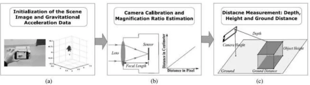
B. Initialization
We now discuss the initialization process. The scene image including the target distance to measure is captured with a hand-held smart mobile device. The accelerometer records the gravitational acceleration at each spatial position when photographing the target scene. Each acceleration datum is a three element vector representing the projection of the gravitation in GX, GY, and GZ axes as Fig. 1 shows. Considering the gravitation is vertical to the ground, we can conclude that the view orientation of the device can be computed directly. For the distance measurement, this direction is required for fulfilling the back-projection which helps to map the pixel distance to the real distance.
C. Camera Calibration and Magnification
back-projected to the ground. Focal length f is required to perform the back-projection operation; hence, we calibrate the camera first to obtain the focal length.
D. Distance Measurement
Fig. 2 illustrates the three types of distance (ground distance, depth, and height) to measure and their corresponding notations. These three types of distance can be the base distances so that an arbitrary distance can be measured. For depth, the bottom point is required to lie on the ground, e.g. a point on the bottom of an object on the ground.
1) Ground Distance: Ground distance can be estimated in a relatively simple way according to the proposed method. For the two examples ground points P1 and P2 shown in Fig. 5, their corresponding image pixels are p1 and p2. To compute the ground distance Lp1p2, p1 and p2 are first back projected from the image plane to their ground points P1 and P2.
2) Depth: Depth is the distance between the camera optical centre and the user-specified point in 3-D space. If the specified point is above the ground, its projection on the ground also has to be specified to determine its position in 3-D space. The depth is also computed with the magnification ratio. For the ground point P1 in Fig. 2 whose corresponding
image pixel is p1, its depth of Dp1 can be computed as follows:
3) Height: Two kinds of height can be measured: 1) Camera From camera optical centre C to the ground while the latter means the distance between two specified points: one for the top of the object and the other as the ground position for the bottom. Similar to the ground distance and depth, the height in the pixel has to be computed first and then multiplied by the magnification ratio. For the camera height Hc shown in Fig. 2, whose bottom C_ is the projection of C on the ground, it can be computed as
Fig .2 measurements for different types of distance
IV. RESULT
The experimental results are shown qualitatively with real Scenes and then quantitatively for analyzing the efficacy of the proposed method. The comparisons with the state-of- the art methods are presented consequently. The measurement accuracy is evaluated by both absolute error and relative error.
A. Qualitative Results
In the real experimental scenes, an Android5.0 is used to Validate the method by photographing one image of each Experimental scene, with the sampling rate of gravitational Acceleration signal being 100 Hz and the image
resolution Being 2592 × 1936. The first experiment is an indoor scene This contains the regular floor blocks on the ground. All the blocks are squares of 60 × 60 cm. Quantitatively Results Measurement distance, view orientation, and known distance can be specified differently by different users and therefore, in this section, statistical experiments on
orientation. However, the change of the view orientation will lead to the change of the intersection angle between the optical axis and the norm of the ground except when the view translates along the XOY plane or rotates around the optical axis. Therefore, we use the varying intersection angle between the optical axis and the norm of the ground to analyses the performance variation view orientation.
III. RESULTS
Fig. 1. Obstacle Distance (m) vs. laser position on screen(pixels)
the x-axis represents the horizontal pixel number of an image. The ordinate axis corresponds to the calculated real distance in meters between obstacle and camera for each pixel on an image.
Fig. 2. Time used by each RTOS task in a 2 milliseconds scale
system performance analysis trough a tool provided by Keil Software[6]. The result shows that the embedded system based on the LPC1768 microcontroller was able to process every frame from camera in less than 2 milliseconds.
III. CONCLUSION
known distance for the measurement. How to measure the distance without the known distance will be considered in our future work.
ACKNOWLEDGMENT
I would like to thanks to my Project Guide, Dr. Jadhavar B.R., E&TC department, Jaihind collage of Engg, Kuran, Who has guided throughout the project work. I would also Extend my thanks to Prof. Mulajkar R.M. and Dhede B.M. madam for helping me for my project work.
REFERENCES
[1] Ming-Chih Lu, Ke-Wei Chin -“Distance Measurement Based on Pixel Variation of CCD Images”- Department of Electrical Engineering Tamkang University Taipei County, Taiwan. International conference on Autonomous robots and agents.
[2] ShihYen Huang1, Yen Cheng Chen -“Measurement of Tire Tread Depth with Image Triangulation”- National Chin-Yi University of Technology, Taiwan Taichung, Taiwan. 2016 International Symposium on Computer, Consumer and Control
[3] Thomas Bucher -“Measurement of Distance and Height in Images based on easy attainable Calibration Parameters”- Institute fur Neuro informatik Ruhr- University at Bochum. IEEE Intelligent Vehicles Symposium 2000.