Robust FIS Implementation of a Fuzzy based
DSTATCOM in VCM for Power Quality
Enhancement
Chowdam Yashoda1, P.Harish Kumar2
P.G. Student, Department of Electrical and Electronics Engineering, CBIT, Proddutur, Kadapa, India1.
Associate Professor, Department of Electrical and Electronics Engineering, CBIT, Proddutur, Kadapa, India2
Abstract: The Power Distribution Systems are often suffered by several power quality problems. Most of these power quality problems are due to several evincing facts like ageing of the power distribution lines and frequent line faults which are the reasons for major part of an un-interrupted power loss. A power quality deviation of the distributed power system shows a serious impact on its robust and sustainable operation. These power quality fluctuations may be caused due to several reasons like leakage, faults and ageing of the lines. In the recent era the Distribution Static Compensator (DSTATCOM)s have emerged as the robust solution for mitigating the power quality deviations. DSTATCOM must be operated in the Voltage Controlled Mode(VCM) to compensate the voltage fluctuations efficiently. In VCM also the performance of the DSTATCOM in power quality regulation and improvement will be steered by an appropriately selected reference control voltage. Selection of an appropriate reference control voltage for the DSTATCOM operating in the control mode is a crucial task, for which several algorithms were proposed in the literature whose performance was not satisfactory. As a solution to this ever teasing problem in this project we proposed a novel algorithm to generate reference control voltage for a DSTATCOM operating in VCM using the robust Fuzzy Logic, which is an extension of a multi-value logic. In this project with an aid of fuzzy-logic DSTATCOM functionality is implemented using Fuzzy Inference System(FIS) which comprises the fuzzy-logic controller and its associated logic circuitry. The proposed algorithm explores several advantages compared to the conventional implementation of DSTATCOM.Thus methods allows effective compensation of power quality issues and provides good voltage regulation with unity power factor at the load terminal during the load change. Compensator injects lower order currents to mitigate the losses in the feeder and the voltage source inverter. The state-space model of DSTATCOM is incorporated with the deadbeat predictive controller for fast load voltage regulation during voltage disturbances. With these features, this method allows DSTATCOM to tackle power-quality issues efficiently. Simulation and experimental results are presented to demonstrate the efficacy of the proposed algorithm.
I.INTRODUCTION
compensate the power quality fluctuations. DSTATCOM can compensate all types of power quality fluctuations in the DPS when it is being operated in the controlled mode. Basically DSTATCOM can be operated in both Current Controlled Mode(CCM) and Voltage Controlled Mode(VCM).A DSTATCOM can compensate both current as well as voltage fluctuations when it is connected at the point of common coupling (PCC).In any DPS most of the power quality deviations may be caused due to deviations in the line voltage levels. Hence the VCM mode of operation is preferred than the CCM mode of operation. When operating in CCM the DSTATCOM injects reactive and harmonic components of load currents to make source currents balanced and in phase with the PCC voltages. In voltage-control mode (VCM) the DSTATCOM regulates the voltage at PCC to a reference value to protect critical loads from voltage disturbances, such as sag, swell, and unbalances. However, one active filter device cannot preserve the advantages of both CCM and VCM simultaneously, since two modes are independent of each other.
The DSTATCOM operating in CCM cannot compensate for voltage disturbances. Hence, CCM operation of DSTATCOM is useless under voltage deviations, which is a major disadvantage of this mode of operation [13]. Traditionally, in VCM operation, the DSTATCOM regulates the PCC voltage at 1.0 p.u. [2], [8]–[11]. However, a load works satisfactorily for a permissible voltage range [14]. Hence, it is not necessary to regulate the PCC voltage at 1.0 p.u. While maintaining 1.0-p.u. voltage, DSTATCOM compensates for the voltage drop in feeder. For this, the compensator has to supply an extra reactive current which increases the source currents. This increases losses in the voltage-source inverter (VSI) and feeder. Due to increased current injection, the VSI is de-rated in steady-state condition. Consequently, its capability to mitigate deep voltage sag decreases. Also, UPF cannot be achieved when the PCC voltage is 1p.u.
This paper considers the operation of DSTATCOM in VCM.But in this VCM operation of DSTATCOM also the operational effectiveness of the DSTATCOM connected at the PCC in compensating the power quality fluctuations will be steered by an appropriate selection of reference control voltage. If the reference control voltage is appropriate then the performance of DSTATCOM in power quality mitigation is optimum. But selection of an appropriate reference load control voltage is a crucial task for which several algorithms were proposed in the literature whose performance was fair and not meeting the present application demands. As an eternal solution to this ever teasing problem we a novel control algorithm to obtain the reference load control voltage for the DSTATCOM being operated in VCM and connected at PCC of DPS using the Fuzzy-Logic based Fuzzy-Inference System(FIS). This algorithm provides the combined advantages of CCM and VCM. The UPF operation at the PCC is achieved at nominal load, whereas fast voltage regulation is provided with an aid of a deadbeat predictive controller which is used to generate switching pulses. The control strategy is tested with a three-phase four-wire DPS. The effectiveness of the proposed algorithm is validated through detailed simulation and experimental results.
II.FUZZY-LOGIC FRAMEWORK
Fuzzy logic is all about the relative importance of precision and is a fascinating area of research because it does a good job of trading off between significance and precision something that humans have been managing for a very long time. The fuzzy logic is both old and new because the methodical science of fuzzy logic is still new and the concept of fuzzy logic relies on age-old skills of human reasoning. Fuzzy logic is a convenient way to map an input space to an output space. Mapping input to output is the starting point for everything. As Lotfi Zadeh, who is considered to be the father of fuzzy logic, once remarked: "In almost every case you can build the same product without fuzzy logic, but fuzzy is faster and cheaper".
A.Fuzzy Inference System(FIS):The Fuzzy Inference System(FIS) is a mechanism that relates the inputs to a specific
Fig(1):Block diagram of the FIS.
Fig(2):FIS Simulink model.
B.Fuzzy-Logic Controller(FLC):
A linguistic term can be defined quantitatively by a type of fuzzy set known as a membership function. The membership function specifically defines degrees of membership based on a property such as temperature or pressure. With membership functions defined for controller or expert system inputs and outputs, the formulation of a rule base of IF-THEN type conditional rules is done. Such a rule base and the corresponding membership functions are employed to analyze controller inputs and determine controller outputs by the process of fuzzy logic inference. By defining such a fuzzy controller, process control can be implemented quickly and easily. Many such systems are difficult or impossible to model mathematically, which is required for the design of most traditional control algorithms. In addition, many processes that might or might not be modeled mathematically are too complex or nonlinear to be controlled with traditional strategies. However, if a control strategy can be described qualitatively by an expert, fuzzy logic can be used to define a controller that emulates the heuristic rule-of-thumb strategies of the expert. Therefore, fuzzy logic can be used to control a process that a human can control manually with expertise gained from experience. The linguistic control rules that a human expert can describe in an intuitive and general manner can be directly translated to a rule base for a fuzzy logic controller
III. PROPOSED METHOD
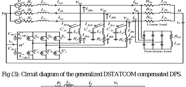
reference control voltage for the DSTATCOM which is designed and implemented using Fuzzy-Logic based FIS system and being operated in VCM. The Circuit diagram of a FIS implemented DSTATCOM compensated DPS is shown in Fig(3). It uses a three- phase, four-wire, two-level, neutral-point-clamped VSI.This structure allows independent control to each arm of the VSI. Fig (4) shows the single-phase equivalent representation of Fig (3). Variable ‘ ’ is a switching function, and can be either or -1 depending upon switching state. Filter inductance and resistance are and , respectively. Shunt capacitor removes high-switching frequency components.
Initially, discrete modeling of the system is presented to obtain a discrete voltage control law, and it is shown that the PCC voltage can be regulated to the desired value with properly chosen parameters of VSI. Then, a generalized procedure to design VSI parameters is presented.The robust Fuzzy-Logic based FIS controller replaces the PI controller in the traditional DSTATCOM to regulate the dc capacitor voltage to a reference value. Based
Fig (3): Circuit diagram of the generalized DSTATCOM compensated DPS.
Fig (4): Single-phase equivalent circuit of the generalized DSTATCOM compensated DPS.
On the concepts of instantaneous symmetrical component theory and complex Fourier transform, a reference voltage magnitude generation scheme is proposed that provides the advantages of CCM at nominal load. The overall controller block diagram is shown in Fig (5).
The state-space equations for the circuit shown in Fig (4) are given by
̇= + (1) Where = ⎣ ⎢ ⎢ ⎢
⎡0 0
0
0 ⎦⎥
⎥ ⎥ ⎤ = ⎣ ⎢ ⎢ ⎢
⎡0 − 0
0 0
0 0 ⎦⎥
⎥ ⎥ ⎤
s=[ ],z=[ ].
The general spatial domain solution of equation (1) to compute the state vector s(t) with known initial value s(t0) is given as follows:
( ) = ( ) ( ) +∫ ( ) ( )
(2) The equivalent discrete solution of the continuous state is obtained by replacing t0=kTd and t=(k+1)Td as follows:
Where k and Td represents the kth sample and sampling period respectively. During the consecutive sampling period,
the value of z(τ) is held constant, and can be taken as z(k). After simplification and changing the variable of integration,
equation (3) can be written as
( + 1) = +∫ ( ) (4)
This equation is rewritten as follows:
( + 1) = ( ) + ( ) (5)
Where C and D are sampled matrices, with the sampling time of Td.For Small sampling time, matrices C and D are calculated as follows:
= = ≈ + + (6)
= =∫ ≈ ∫ ( + ) . (7)
Hence the capacitor voltage is given as
( + 1) = ( ) + ( ) + ( ) + ( ) (8)
From eq.(8), the terminal voltage can be maintained at a reference level depending upon the VSI parameters , , , and sampling time .Therefore, VSI parameters must be chosen carefully. Let ∗ be the reference load terminal voltage. A cost function E is chosen as follows.
E= [ ( + 1)− ∗( + 1)] (9)
The cost function is differentiated with respect to u(k) and its minimum is obtained at
( + 1) = ∗( + 1) (10)
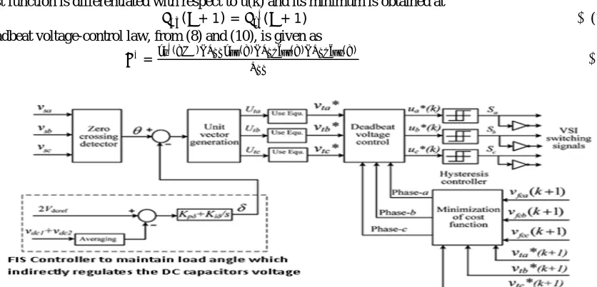
The deadbeat voltage-control law, from (8) and (10), is given as
∗= ∗( ) ( ) ( ) ( )
(11)
Fig (5): Schematic block diagram of the FIS controller to control DSTATCOM in the DPS.
The overall schematic block diagram of the proposed FIS controller to control the DSTATCOM in DPS is shown in fig(5),which consists of a zero crossing detector which detects the zero crossing points in three phasor voltage waveforms. In the conventional DSTATCOM, PI Controller(PIC) is used to control the DSTATCOM,but it cannot compensate multiple fluctuations and errors simultaneously. But FIS controller based DSTATCOM can compensate multiple fluctuations and errors simultaneously. Using the result from the zero crossing detector and load angle from the FIS controller to maintain dc capacitor voltage, the Unit Vector Generator (UVG) generates three unit threshould vectors for three phasor voltage lines of the DSTATCOM which will be further optimized according to the characteristic equation.
∗
The dead beat voltage controller regulates the voltage fluctuations in three Phasor lines in proportion to the feedback control phase sample inputs for three Phasor lines so as to control the cost of power quality regulation process according to the cost function conditionally steered by functional and threshould voltages of three phasors lines of the DSTATCOM.Thus the discrete functional units of DSTATCOM will work.
Reference terminal voltages are generated such that, at nominal load, all advantages of CCM operation are achieved while DSTATCOM is operating in VCM. Hence, the DSTATCOM will inject reactive and harmonic components of load current. Then, it is assumed that these currents come from the source and considered as reference source currents at nominal load. With these source currents and for UPF at the PCC, the magnitude of the PCC voltage is calculated. Let three-phase load currents. ( ), ( ) and ( ) be represented by the following equations.
( ) = √2 sin ( +∅ )
Where j=a,b,c represent three phases, ‘n’ is the harmonic number, and ‘m’ is the maximum harmonic order.∅
represents the phase angle of the nth order harmonic with respect to reference in phase-a and is similar to other phases.
IV. RESULTS AND DISCUSSION
The practical realization of the proposed algorithm for generating the reference voltage of the DSTATCOM operating in the control mode for stable voltage regulation and analysis of a DPS is done by designing the corresponding DSTATCOM using Fuzzy-Logic based FIS, which internally implements a FLC, which accelerates the operational efficiency of the DSTATCOM in detection and compensation of voltage/power quality fluctuations. Simulink models of the proposed fuzzy-logic based DSTATCOM circuits are designed hierarchically to replicate functional efficiency of various processing stages involved in designing the DSTATCOM and various processing models using MATLAB/SIMULINK software.
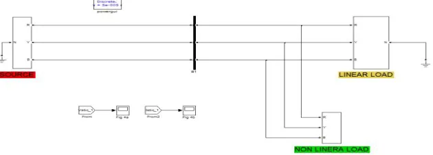
Fig (6): Uncompensated generalized DSTATCOM model.
The basic DSTATCOM model before compensating the spurious voltage fluctuations in the phasor lines of the DPS is shown in above figure(6).This model will consists of a Distributed Generation based power generation unit which supplies the power to the load units through the three phase lines. The load unit can be either linear load unit or non-linear load unit. The output voltage levels will be displayed on the Oscilloscopes.
Fig (8):Uncompensated DSTATCOM terminal current graphs of the three phasor lines.
The below figure(9) shows the generalized DSTATCOM model, which employs a similar circuitry as that of the DSTATCOM model without compensation as shown in fig(6) in addition with a compensation circuitry with Proportional Integral(PI)controller to compensate the voltage fluctuations in the phasor lines of the power distribution system.
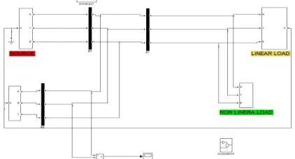
Fig (9): Compensated PI Controller based Generalized DSTATCOM Model.
Fig (10): Compensated FIS controller based generalized DSTATCOM model using Fuzzy logic.
Fig(12):Terminal voltage and currents graphs of the PIC based DSTATCOM model.
Fig(13): RMS Compensator current graph of PIC based DSTATCOM model .
Fig (14): Active Power graph at the load terminals of the PIC based DSTATCOM model.
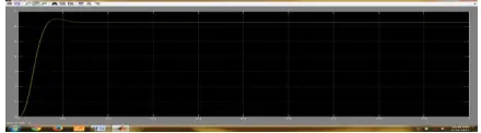
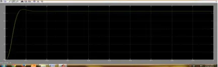
Fig(15):Terminal voltage graph of the FIS based DSTATCOM model .
Fig(18):combined voltage and currents graph at the terminals of the FIS based DSTATCOM model.
Fig (20): Source voltage graphs of the three phasor lines of the FIS based DSTATCOM model.
Fig (21): Source current graphs of the three phasor lines of the FIS based DSTATCOM model.
Fig (22):Compensation current of the FIS based DSTATCOM model.
Fig (23): Active Power graph at the load terminals of the FIS based DSTATCOM model.
V.CONCLUSION
In this work, we proposed, designed and implemented a novel control algorithm using the robust FIS, which internally implements the FLC for the generation of reference load control voltage for a VCM operated DSTATCOM. The performance characteristics of the proposed method are compared with those of PIC controlled DSTATCOM.The proposed FIS based implementation provides the following advantages at normal operational load which includes achieving UPF at load in addition to the fast voltage regulation at load during load unbalances. Also the losses in the VSI and feerders are reduced tremendously and provides higher sag mitigation capability compared to the traditional PIC based scheme. The simulation and experimental results show that the proposed FIS-DSTATCOM scheme provides a capability to improve several power quality issues.
VI.FUTURE SCOPE
Control voltage optimization enables the reference voltage design to be appropriate which enables the FIS based DSTATCOM to deliver best of its performance.
REFERENCES
[1] M. Bollen, Understanding Power Quality Problems. Piscataway, NJ,USA: IEEE, 2000, ch. 1, pp. 1–35.
[2] H. Fujita and H. Akagi, “Voltage-regulation performance of a shunt active filter intended for installation on a power distribution system,” IEEE Trans. Power Electron., vol. 22, no. 3, pp. 1046–1053, May 2007.
[3] A. Ghosh and G. Ledwich, “Load compensating DSTATCOM in weak ac systems,”IEEE Trans. Power Del., vol. 18, no. 4, pp. 1302–1309,Oct. 2003.
[4] A. Elnady and M. Salama, “Unified approach for mitigating voltage sag and voltage flicker using the DSTATCOM,” IEEE Trans. Power Del., vol. 20, no. 2, pt. 1, pp. 992–1000, Apr. 2005.
[5]S.Rahmani,A.Hamadi,andK.Al-Haddad,“ALyapunov-functionbased control for a three-phase shunt hybrid activefilter,”IEEE Trans.Ind. Electron., vol. 59, no. 3, pp. 1418–1429, Mar. 2012.
[6] M. K. Mishra and K. Karthikeyan, “A fast-acting dc-link voltage controller for three-phase DSTATCOM to compensate ac and dc loads,” IEEE Trans. Power Del., vol. 24, no. 4, pp. 2291–2299, Oct. 2009.
[7] M. K. Mishra, A. Ghosh, A. Joshi, and H. M. Suryawanshi, “A novel method of load compensation under unbalanced and distorted voltages,”IEEE Trans. Power Del., vol. 22, no. 1, pp. 288–295, Jan. 2007.
[8]M.K.Mishra,A.Ghosh,andA.Joshi,“Operationof a DSTATCOM in voltage control mode,”IEEE Trans. Power Del.,vol.18,no.1,pp. 258–264, Jan. 2003.
[9] A. Jain, K. Joshi, A. Behal, and N. Mohan, “Voltage regulation with STATCOMs: Modeling, control and results,”IEEE Trans. Power Del.,vol. 21, no. 2, pp. 726–735, Apr. 2006.
[10] R. Gupta, A. Ghosh, and A. Joshi, “Switching characterization of cascaded multilevel-inverter-controlled systems,”IEEE Trans. Ind. Electron., vol. 55, no. 3, pp. 1047–1058, Mar. 2008.
[11] P. Mitra and G.Venayagamoorthy, “An adaptive control strategy for DSTATCOM applications in an electric ship power systems,”IEEE Trans. Power Electron., vol. 25, no. 1, pp. 95–104, Jan. 2010.
[12] A. Yazdani, M. Crow, and J. Guo, “An improved nonlinear STATCOM control for electric arc furnace voltage flicker mitigation,”IEEE Trans.Power Del., vol. 24, no. 4, pp. 2284–2290, Oct. 2009.
[13] S.-H. Ko, S. Lee, H. Dehbonei, and C. Nayar, “Application of voltage and current-controlled voltage source inverters for distributed generation systems,”IEEE Trans. Energy Convers., vol. 21, no. 3, pp.782–792, Sep. 2006.
[14] M. Moradlou and H. Karshenas, “Design strategy for optimum rating selection of interline DVR,”IEEE Trans. Power Del., vol. 26, no. 1,pp. 242–249, Jan. 2011.
BIOGRAPHY
1
C.Yashoda received the B.Tech degree in Electrical and Electronics Engineering from Vaagdevi Institute of Technology And Science, Proddatur, Kadapa, A.P., India in 2012 and is currently pursuing the M.Tech(Electrical power systems) degree in Electrical Engineering at Chaitanya Bharathi Institute of Technology, Proddatur, A.P., India. My research interests include power-electronic applications in power systems and power quality.
2