SITE RESPONSE ANALYSIS OF THE COMPLEX FOUNDATION BASED
ON DYNAMIC ARTIFICIAL BOUNDARY FOR NUCLEAR POWER
ENGINEERING
LI Zhongcheng1, FAN Hong1, and LI Jianbo2
1
Deputy Manager, China Guangdong Nuclear Power Design Company, CHINA 2
Deputy Professor , Dalian University of Technology, CHINA
ABSTRACT
Site response analysis under the action of earthquake is a very important part of the evaluation of site dynamic characteristics and foundation of adaptability. For a typical nuclear power engineering example with the complex foundation in China, the site response analysis is performed based on the viscoelastic boundary and the transmitting boundary developed as a means of modeling the soil foundation, and the calculation effectiveness and their difference are illustrated as well. The basic principles of the calculation method and model selection in dealing with dynamic complex foundation problems are discussed in this paper. The research results have important reference value for the dynamic analysis and evaluation of complex foundation of the nuclear power engineering.
INTRODUCTION
Earthquake is one of the most important external events and must be considered in the design and safety assessment of nuclear power plants; it has very huge economic and safety effects on the nuclear power projects. The site response analysis under the action of earthquake is an important part of the evaluation on the site dynamic characteristics and foundation of adaptability.
Under the action of dynamic load, the essence of the response of site is the semi-infinite space problem, which belongs actually to the infinite domain problems. For this kind of problem, an analytical solution can be get only for the homogeneous foundation under the simple incentive effects[Wolf (1985), Luco(1976)]. For the complex foundations with uneven materials, it is impossible to solve its’ analytical solution. Owing to the 3D finite element technology, the modelling of the dynamic characteristics can be realised based on the artificial boundary[LI(2014)].
In this paper, For a typical nuclear power engineering example with the complex foundation in China, the site response analysis is performed based on the viscoelastic boundary and the transmitting boundary developed as a means of modeling the soil foundation, and the calculation effectiveness and their difference are illustrated as well. The basic principles of the calculation method and model selection in dealing with dynamic complex foundation problems are discussed in this paper. The research results have important reference value for the dynamic analysis and evaluation of complex foundation of the nuclear power engineering.
EARTHQUAKE CHARACTERISTICS
Actual nuclear power engineering is selected as an example, which is named as H power plant and located in the northeast area in China. According to the results of seismic risk evaluation, the site specific parameters of the ultimate safety ground motion (SL-2) are shown in Table 1.
Acceleration peak value in horizontal
/ g
Acceleration peak value in vertical
/ g Response spectra
0.18 0.12 Site-specific response
spectra
The time histories in acceleration are shown in Figure 1, which are generated from the site specific response spectra according to the requirements on the accuracy and statistical independence. The duration and the step of the time histories are 25.0s and 0.01s respectively.
SOIL CONDITION
The nuclear island foundation selected belongs to rocky foundation, but the partial uneven characteristic is also relatively prominent, its lithology and its distribution features are more representative. The main parts of the nuclear island area foundation is moderately weathered rock, and some strong weathering rocks of weaker xenoliths locally distributed, such that the spatial distribution of lithology is extremely uneven. Some more complicated soil materials are defined as a comprehensive geological body. The finite element model of the foundation is shown in Figure 2. The main dynamic parameters of foundation materials are shown in Table 2.
Table 2: Dynamic parameters of soil
Lithology Modulus
/ MPa Poisson ratio Shear velocity/ m.s -1
Moderately weathered rock 14701 0.34 1462
Comprehensive geological body 14021 0.38 1425
Slightly weathered rock 25203 0.36 1902
Strongly weathered rock˄xenoliths˅ 6849 0.46 1034
DYNAMIC ARTIFICIAL BOUNDARIES Time / s
A
cc
el
er
at
io
n
/
g
a Horizontal-X
Time / s
A
cc
el
er
at
io
n
/
g
b Vertical-Z
Figure1. Diagram of input ground motion in acceleration
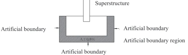
Two kinds of the dynamic artificial boundaries, which are the viscoelastic boundary and the transmitting boundary developed on the ANSYS platform, are employed to model the dynamic features of foundation. The viscoelastic artificial boundary was developed in the viscous boundary based on traditional, its physical concept is very clear, that is using the artificial boundary which is formed by spring damper system to simulate the scattering wave radiation and ground recovery characteristics, and the literature [LI(2014)] has a detailed description of this method. The viscoelastic artificial boundary model is shown in Figure 3.
The artificial transmitting boundary can directly simulate all kinds of unilateral wave kinematics process, has nothing to do with the particularity of the wave field equation. In general, the multi transmitting artificial boundary model is established based on the incident waves from the unilateral elastic plane wave as the starting point, the model shown in Figure 4, its’ basic principle is as follows:
In Figure 4, the artificial boundary point O is the origin of the X axis, the plane x=0 is the artificial boundary and the area x<0 is the computational domain. For scattering wave propagating from the computational domain to artificial boundary point o, it can be seen as introverted with the apparent speed of Ca along the X axis from the x<0 side at the boundary point.
Multi transmitting formula is commonly used and it can be represented as the discrete field movement of the discrete calculation points, as follows:
!
$ ,% $"
, #0,1,2,3,...; #0,1,2,3,...#u p dt jC dt p j
u a
p
j (1)
In which, dt is the time interval. The formula (1) just represents the displacement of the point with X axis coordinate for the point in time. Therefore, the displacement u0p&1 of the artificial boundary node M0 (x=0 point on the X axis) at the moment of (p&1)$dt, can be expressed as:
! "
'
#% & & & # %
N
j
j p j N j j p
u C u
1
1 1 1
0 1
(2)
In which, is the binomial coefficient:
! "!!
!
j j N
N CN
j
%
# (3)
From equation (2), the local features of the artificial boundary condition can be seen, that is, the movements of the boundary nodes are only related to the neighboring nodes in adjacent time. The ujp&1%j
in equation (2) is the computational node and is generally different with the node of finite
Figure 3. Illustration of the artificial viscoelastic boundary
element model. In Figure 4, points of M0, M1, M2 represent the calculation points in the multi transmitting formula, and the points of 0, 1, 2; 4, 3, are the nodes of the finite element model. Therefore the motion of calculation point will be get using the finite node interpolation.
In order to facilitate the application of multi transmitting formula, the artificial boundary region outside the foundation area shall be set, in this region, the calculation points along the artificial boundary axis can be defined with the node distance ofƸX. For the interpolation method, some details can be found in reference [LI(2005)].
ҎᎹ䖍⬠
ҎᎹ䖍⬠ ҎᎹ䖍⬠
ҎᎹ䖍⬠ऎ 㒧ᵘ
SITE SEISMIC RESPONSE ANALYSIS
By using two artificial boundary conditions of foundation, 3D finite element model is established to simulate the effect of foundation. The site seismic response analysis is carried out using the artificial wave fitting with the site specific response spectra as seismic input.
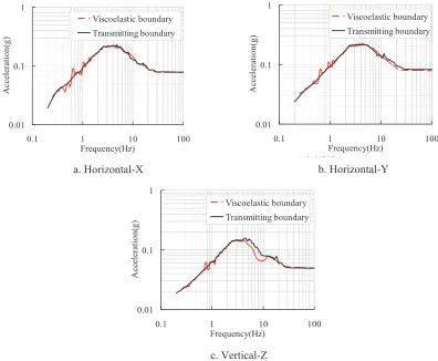
The circular raft, the radius of it is 19.8m, is selected as the object of study. The seismic response at the centre of the raft is investigated and discussed. The free field acceleration response spectra obtained from site response analysis are shown in Figure 6, and the response spectra are just for the 1/2 SL-2 as input and the goal of damping ratio of 5% results.
From the results in Figure, the almost similar calculation results based on the two different types of dynamic artificial boundary models shows that the two kinds of artificial foundation boundaries developed have the similar effect of in dealing with complex foundation response analysis. It is also found that the results of viscoelastic boundary model appear a certain degree fluctuation at low frequencies; this is because the frequency sampling density is a little excessive, if the frequency interval is increased appropriately in accordance with design codes, the oscillation situation of spectral line in low frequency is expected to ease.
CONCLUSION
The viscoelastic boundary and the transmitting boundary are the two kinds of artificial boundaries widely used in engineering. In this paper, the site response analysis of complex foundation of a typical nuclear power project in China is carried out. It is demonstrated that the two types of artificial boundaries have the good function to simulate the dynamic effect of foundation and can give a reasonable dynamic response laws. The two types of artificial boundary conditions of foundation can be widely used in nuclear power engineering. In view of the special nature of the seismic response of complex foundation, it is suggested to use multiple foundation models in nuclear power engineering. Research has important reference values on the dynamic analysis and evaluation of complex foundation for the nuclear power
Artificial boundary Artificial boundary
Artificial boundary
Superstructure
Artificial boundary region
engineering. The two kinds of methods are also employed in another project, Fangchenggang nuclear power project in Guangxi province in China.
REFERENCES
Wolf J.P. (1985). “Dynamic Soil-structure Interaction”, Prentice-Hall.
Luco J.E. (1976). “SSI- an Engineering Evaluation”, Nuclear Engineering and Design, 38: 267̚272. ASCE 4-98. (1998). “Seismic Analysis of Safety-Related Nuclear Structures and Commentary on
Standard for Seismic Analysis of Safety-Related Nuclear Structures”, US.
LI Zhongcheng. (2006). “Seismic Response Analysis of Nuclear Power Plants Considering Soil-Structure Interaction Effects”, PhD dissertation, CHINA.
LI Zhongcheng, FAN Hong. (2014). “Dynamic Impedance Analysis Based on an Artificial Viscoelastic Boundary Technology for Nuclear Power Engineering”, Nuclear Power Engineering, 35: 67~70. LI Jianbo. (2005). “Study on the method of time-domain numerical analysis of dynamic soil structure
interaction”, PhD dissertation, CHINA.
b∈ᑇᮍY
Figure 6. Diagram of ground motion response spectra in acceleration a. Horizontal-X
0.01 0.1 1
0.1 1 10 100
Frequency(Hz)
A
cc
el
er
at
io
n
(g
)
Viscoelastic boundary
Transmitting boundary
0.01 0.1 1
0.1 1 10 100
Frequency(Hz)
A
cc
el
er
at
io
n
(g
)
Viscoelastic boundary
Transmitting boundary
0.01 0.1 1
0.1 1 10 100
Frequency(Hz)
A
cc
el
er
at
io
n
(g
)
Viscoelastic boundary
Transmitting boundary
b. Horizontal-Y