Transient Stability of Two Machine System
with Static Var Compensation
Deepak Bhataniya1, Rakesh Singh Lodhi2
M. Tech. Student, Department of Electrical & Electronics Engineering, Oriental University, Indore, India1
Asst. Professor, Department of Electrical & Electronics Engineering, Oriental University, Indore, India2
ABSTRACT: Transient stability control plays a significant role in ensuring the stable operation of power systems in the event of large disturbances and faults. This paper focuses on the significant of SVC (Static Var Compensator) to improve the transient stability of power transmission system in abnormal conditions. In the simulation result of model for different conditions with SVC and without SVC and Static Var Compensator (SVC) has effectively been applied to two machine systems for efficiently regulating system voltage and thus increase system load ability. It investigates the effects of (SVC) on voltage stability of a power transmission system at center positions. SVC controlling the reactive power flow to the 700km. line. The model is simulated using the MATLAB/SIMULINK software.SVC is effective in midpoint voltage regulation on transmission line. In paper comparison is also performed between SVC and without SVC under fault condition. The combination of TCR and TSC in the SVC configuration is used. The result shows the reactive power is compensated and system is in stable condition.
KEYWORDS: Static Var Compensator (SVC), Power System Stabilizer (PSS), TSC, TCR, without fault, Multi-Machine System.
I. INTRODUCTION
For many years, one of the major interests that power system should fulfil is satisfying sufficient conditions of stability. This interest is becoming a serious concern [2]. Indeed, in the one hand, the energy market evolution while the weakness of the transmission net due to financial difficulties and high costs of rights, don’t make viable the construction of new lines and hence the higher loading of existing transmission lines. Disequilibrium between mechanical and electrical power can be instituted, this can affect rotor speed variations and can lead to a partial or total outage [5]. It is well established that power system stabilizer is the first measure that has been used to improve damping oscillations of power system during electromechanical transients. Stability of this system needs to be maintained even when subjected to large low-probability disturbances so that the electricity can be supplied to consumers with high reliability. The FACTS Technology is not a single high power controller but rather a collection of controllers which can be applied individually or in coordination with other to control one or more of the inter related System parameters like voltage, current, impedance, phase angle and damping of oscillations at various frequencies below the rated frequency. Among all FACTS devices, SVC plays much more important role in reactive power compensation and Voltage support because of its attractive steady state performance and operating characteristics.
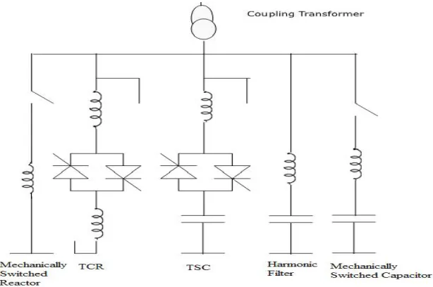
II.STATIC VAR COMPENSATOR
with combination of mechanically switched reactor, TCR, TSC, harmonic filter and mechanically switched capacitor configuration as shown in Figure1.
The static VAR compensator is an automated impedance matching device, designed to bring the system closer to unity power factor. SVCs are used in two main situations:-
1. Connected to the power system, for regulate the transmission voltage (Transmission SVC) 2. Connected near large industrial loads, for improve power quality (Industrial SVC)
Figure 1 Static VAR Compensator
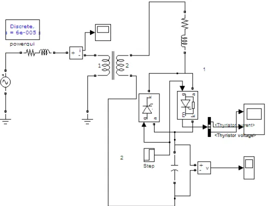
III.SIMULINK MODEL OF TCR
In this model the synchronized pulse generators firing thyristors Th1 and Th2. Copy two Simulink pulse generators into your system, name them Pulse1 and Pulse2, and connect them to the gates of Th1 and Th2.
IV.SIMULINK MODEL OF TSC
Now modify and change the TCR branch to a TSC branch. Connect a capacitor in series with the RL inductor and Th1/Th2 valve as shown in Figure3.Contrary to the TCR branch, which was fired by a synchronous pulse generator, a continuous firing signal is now applied to the two thyristors.
Figure 3 Simulink Model of TSC
V.TWO MACHINE TRANSMISSION SYSTEM WITH & WITHOUT SVC
Case 1 without SVC
A problem has been taken of two machine models consisting of three bus model for transients stability using MATLAB/Simulation. To see the effect of the without SVC in the system voltage wave form when the system subjected to three phase fault, a two machine system is developed with three buses.
Power plants are employed with random generators as shown. Case 2 with SVC
Figure 4 Block Diagram of Transmission System with SVC
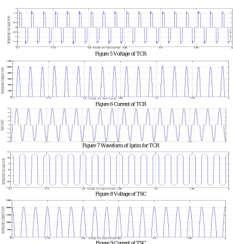
VI.SIMULATION RESULT
Figure 5 Voltage of TCR
Figure 6 Current of TCR
Figure 7 Waveform of Iprim for TCR
Figure 8 Voltage of TSC
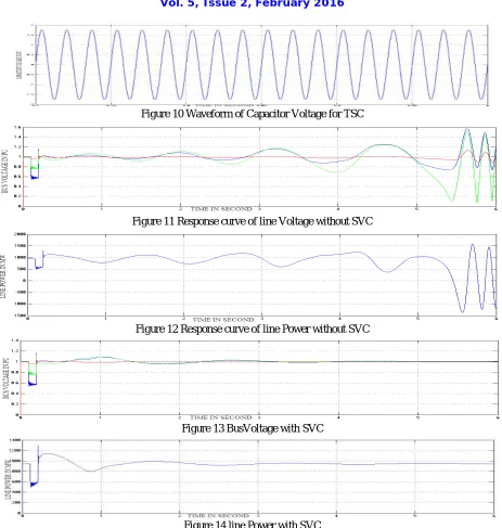
Figure 10 Waveform of Capacitor Voltage for TSC
Figure 11 Response curve of line Voltage without SVC
Figure 12 Response curve of line Power without SVC
Figure 13 BusVoltage with SVC
Figure 14 line Power with SVC
VII. RESULT ANALYSIS
Table 1 Transient Analysis
S. No. Parameter Without SVC With SVC Conclusion
1 Voltage 1.5763 pu 1.165pu Transient Reduced Voltage
2 Power 1587.1 watt 1297.3961
watt
Transient Reduced Power
Table 2 Transient Time
S. No. Without Fault With Fault
1 Stable Unstable
VIII.CONCLUSION
The proposed model is oscillation and instable with absence effect of (PSS) & (SVC).Using effects of (PSS) & (SVC) will increase the stability of proposed model after occurred and cleared faults. The selective of (PSS) are capable of proving sufficient damping to the steady state oscillation and transient stability voltages performance over a wide range of operating conditions and various types of disturbances of the system used in proposed model. From the simulation we can conclude that using power system stabilizer we can stabilize our system up to certain limit and maintain the synchronism between the inter connected area and protect the whole power system from cascade tripping which is very serious matter. We can also say that only using PSS we cannot maintain stability but in some cases or condition it is require using SVC to maintain stability
REFERENCES
[1] Houari boudjella, Fatima Zohra gherbi, Fatiha lakdja “Modelling and Simulation of Static VAR Compensator (SVC) in Power System Studies by Matlab” The Annals of “Dunarea De Jos” University of Galati Fascicle iii, 2008.
[2] Alisha Banga and S.S. Kaushik “Modeling and Simulation of SVC Controller for Enhancement of Power System Stability”International Journal of Engineering and Technology, July 2011.
[3] Habibur Rahman, Md. Fayzur Rahman, Harun- Or-Rashid “Voltage Level Improvement of Power System By Using SVC With POD Controller”International Journal of Advanced Technology & Engineering Research.
[4] Tarlochan Kaur and Sandeep Kakran “Transient Stability Improvement of Long Transmission Line System by UsingSVC” International Journal of Advanced Research in Electrical, Electronics and Instrumentation Engineering October 2012.
[5] Alok Kumar, Surya Bhushan Dubey “Enhancement of Transient Stability in Transmission Line Using SVC Facts Controller”International Journal of Recent Technology and Engineering(IJRTE) May 2013.
[6] Ghanshyam Vishwakarma and Nitin Saxena “Enhancement of Voltage Profile by Using Fixed Capacitor-Thyristor controlledReactor (FC-TCR)” International Journal of Electrical, Electronics and Computer Engineering 2013.
[7] Pardeep Singh Virk, Vijay Kumar Garg “Power System Stability Improvement of Long Transmission Line System by Using Static Var Compensator (SVC)” Pradeep Singh Virk et al.Int. Journal of Engineering Research and Applications Oct 3013.
[8] Roberto Alves , Miguel Montilla , Ernesto Mor “ Increase of Voltage Stability and power Limits Using A Static VAR Compensator”
[9] Ravi Kumar Sahu and Nitin Saxena “Dynamic Performance of Power Transmission system improvement using Static Var Compensator” International Journal of Electrical, Electronics and Computer Engineering 2013.
[10] M Asrar Ur Rahman and M Sabah ul Islam “Voltage Control and Dynamic Performance of power Transmission Using Static VAR Compensator” International Journal of Inter-disciplinary and Multi disciplinary Studies,2014.
[11] B. Lakshmana Nayak “ Desing, Modeling and Simulation of VAR Compensation Using Fuzzy Control SVC in Long Transmission Line” International Journal of Advanced Technology, February 2014.
[12] Ganesh Barve “Application Study of FACTS Devices in Indian Power System” IJCAT International Journal of Computing and Technology February 2014.
[13] Narain G.Hingorani & Laszlo Gyugyi Understanding FACTS. Concepts and Technology of Flexible AC Transmission Systems.
[14] Avneesh Kumar Vishwakarma, Dharmeshwari Sahu “Efficient Voltage Regulation in Three Phase A.C. Transmission Lines Using Static VAR Compensator” International Journal of Advanced Research in Electrical, Electronics and Instrumentation Engineering, May 2013.
[15] P. Kundur, Power System Stability and Control, EPRI Power System Engineering Series, New York, 1994).
[16] N. Mithulananthan, Claudio A. Ca˜nizares, John Reeve and Graham J. Rogers “Comparison of PSS, SVC and STATCOM Controllers for Damping Power System Oscillations”.
[18] Abhishek Gandhar, Balwinder Singh, Rintu Khanna “Impacts of Facts Technology-A State of Art Review”International Journal of Innovative Technology and Exploring Engineering, September 2012.
[19] R. Mohan Mathur Ontario Power Generation Toronto,ON, Canada Rajiv K.Varma Indian Institute of Technology Kanpur, India “Thyristor-Based Facts Controllers ForElectrical Transmission Systems.
BIOGRAPHY
Deepak Bhataniya born on 01st Oct. 1987, Khargone, Madhya Pradesh, India. He received the Bachelor of Engineering Degree in Electrical and Electronics Engineering from RGPV Bhopal, Madhya Pradesh. He is perusing the M. Tech. Degree in Electrical Power System from Oriental University Indore, Madhya Pradesh, India.