warwick.ac.uk/lib-publications
Manuscript version: Author’s Accepted Manuscript
The version presented in WRAP is the author’s accepted manuscript and may differ from the
published version or Version of Record.
Persistent WRAP URL:
http://wrap.warwick.ac.uk/120858
How to cite:
Please refer to published version for the most recent bibliographic citation information.
If a published version is known of, the repository item page linked to above, will contain
details on accessing it.
Copyright and reuse:
The Warwick Research Archive Portal (WRAP) makes this work by researchers of the
University of Warwick available open access under the following conditions.
Copyright © and all moral rights to the version of the paper presented here belong to the
individual author(s) and/or other copyright owners. To the extent reasonable and
practicable the material made available in WRAP has been checked for eligibility before
being made available.
Copies of full items can be used for personal research or study, educational, or not-for-profit
purposes without prior permission or charge. Provided that the authors, title and full
bibliographic details are credited, a hyperlink and/or URL is given for the original metadata
page and the content is not changed in any way.
Publisher’s statement:
Please refer to the repository item page, publisher’s statement section, for further
information.
Development of a Lithium-ion Battery Model and State of Charge
Estimation Algorithm with Hardware-in-the-loop Validation
Erik Martinez-Vera
1, James Marco
1, Juan Manuel Ramirez-Cortes
2, Jose Rangel-Magdaleno
21.
Warwick University, International Digital Laboratory WMG, Coventry, UK
2.
National Institute of Astrophysics, Optics and Electronics, Electronics Department, Puebla, Mexico
Abstract A full-order Linear Observer is designed to estimate the State of Charge using a model of a Lithium-ion 18650 cell. The battery model consists of an Equivalent Circuit Network with parameters from test data of an actual cell provided as a function of State of Charge, temperature and Open Circuit Voltage. The model is validated against a current and voltage profile obtained from a real-world drive scenario. The observer is designed as a linearization of the state-space representation of the Equivalent Circuit Network and offline simulation is used to verify its robustness. With a Hardware-in-the-loop setup, the battery model and observer are implemented and results compared against the offline simulations showing strong agreement; thus, validating in real-time the estimation algorithm. Analysis of the results suggest that battery degradation affects the accuracy of the observer thus noting the need to update its parameters in real-time.
Keywords Observer design, Hardware-in-the-Loop (HIL),
Lithium-ion Batteries
I. INTRODUCTION
Lithium-ion batteries have been used as part of the Energy Storage System for Hybrid and Electric Vehicles as an alternative to replace fossil fuels or improve its efficiency in automotive vehicles. As well, in order to decrease the emissions of greenhouse gases and toxic pollutans from internal combustion engines which have been linked to adverse health effects in urban environments [1], [2]. Lithium-ion batteries are prefered over other methods of energy storage, and other battery chemistries due to its higher energy and power to weight ratios [3], [4].
Automotive Energy Storage Systems consists of hundreds or thousands of cells added together to meet the energy and power required by the traction motor as well as the ancillary equipment. To ensure safe and efficient operation of the system, physical devices and control algorithms must be implemented. Battery Management Systems (BMS) include the hardware and software required to monitor the status of the cells avoiding conditions of under/overcharging during operation of the batteries [5], [6]. Both conditions can result in irreversible damage to the cells reducing its capacity to store and transfer charge; thus, shortening the life-span of the overall system. Also, careful control must be implemented during battery normal operation and charging to avoid excessive increase in temperature resulting in premature ageing or even inducing the cells into thermal runaway [7], [8]. To prevent this, the BMS must monitor the state of the cells by means of
physical sensors; however, some states cannot be measured directly as is the case of the charge available in the cells, or State of Charge (SOC). Failure to accurately estimate the SOC would result not only in the aforementioned conditions but also in a system that poorly predicts the remaining range of the vehicle. Then, extensive research has been performed to implement accurate SOC estimation algorithms [9], [10].
Validation of BMS algorithms requires the use of dedicated facilities to cycle the batteries which is expensive, time consuming and presents safety hazards [11], [12]. Using a computer model of a battery that outputs the voltage response to a given current input has been used for development of battery estimation algorithms without incurring in the difficulty of cycling actual cells. Different computer models for batteries exist based on the intended final application mainly classified as Electrochemical models and Equivalent Circuit Networks (ECN). Electrochemical models are high fidelity models that represent the physical reactions occurring inside the cell and are usually used for cell design purposes. They consist of a system of Partial Differential Equations that must be solved using computer expensive numerical methods or through complex procedures to obtain reduced order models [13][15]. On the other hand, ECN are simplified representations that use circuit components as resistors or capacitors to emulate the battery terminal voltage output given a current input. Though they are less accurate than the Electrochemical models, they are also less complex and less resource demanding for computer applications. Hence, they are used for real-time validation of estimation algorithms [16], [17].
Hardware-in-the-loop (HIL) methodology has been used to accelerate development of components in the automotive industry by using a computer model of a system in a closed loop with a physical component [18][21]. The computer model can be modified and updated without having to change the physical test facility which gives flexibility, reducing costs. This approach allows to test control and estimation algorithms to be later embedded in Electronic Control Units in charge of managing the engine, motors, transmission and energy storage systems or to regulate the interactions between them [22].
The objective of this paper is to present the development of a State of Charge estimation algorithm and its verification against an Equivalent Circuit Network model of a lithium-ion 18650 cell in a Hardware-in-the-Loop setup. Accurate real-time capable SOC algorithms are required to develop robust
Battery Management Systems for the next generation of automotive vehicles based on alternative fuel energies.
II. BATERY MODEL
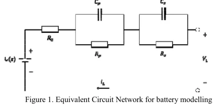
Different types of ECN models have been proposed and can be categorized according to the components included in the circuit as Thevenin, Impedance and Runtime Networks [23]. Thevenin models include resistors and capacitors to represent the electrochemical processes of the battery, Impedance models add complex impedances to represent the diffusion processes inside the cell, Runtime networks include current and voltage controlled sources to also estimate the battery lifetime. The simplest ECN is a Thevenin model consisting of a voltage source in series with a resistance to represent the battery open circuit terminal voltage and internal resistances, respectively. Improved accuracy can be obtained by adding components to the circuit as capacitors and inductors; however, this increases the complexity of the model and could require longer times for its solution. A Thevenin model with a voltage source in series with a resistance and a resistor-capacitor network is proposed in [24] to model a lithium-ion 18650 cell for real-time analysis of the effects of individual cell degradation in a system of cells. A runtime model is presented in [23] including a Thevenin circuit with two resistor-capacitor networks accounting for the short and long term transient response of a battery to a step change in current. Also, the Open Circuit Voltage is as function of cell ageing and state of charge. The BMS estimation algorithms proposed in [25] use Impedance and Thevenin models with parameters obtained through an applied AC signal of varying frequency to obtain the battery complex impedance behaviour in the frequency domain, a procedure defined as Electrochemical Impedance Spectroscopy (EIS). Comprehensive reviews of battery modelling methods can be found in [16], [17] including different ECN as well as Electrochemical models. The experimental comparison of five different ECN performed in [26] showed that using a Thevenin network with two resistor-capacitor pairs gave better accuracy without increasing complexity of the model. This network, as displayed in Fig. 1, has been used for development of estimation algorithms in [23], [27][29].
From Fig. 1, the voltage source U(z) represents the battery
Open Circuit Voltage (OCV) as a function of the state of charge. The combined model [30], is used to describe this relationship as per (1) where parameters k1 k4 are constants
for model fitting using Linear Least Squares and z is the standard Coulomb counting method for SOC estimation as
defined in (2) with as the battery nominal capacity.
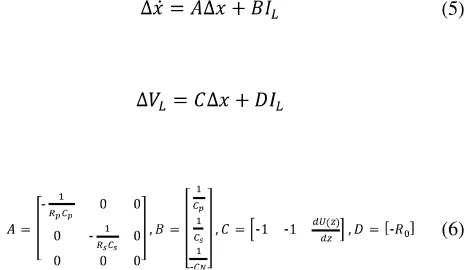
The ECN proposed includes the SOC and the voltages across the capacitors , as the states, the current as the input and the load voltage , as the output. Then, (3) is the state-space representation of the system with (4) as the output equation. Derivation of these is omitted yet procedures for state-space system representation is found in [31], [32].
The data for the U(z) relationship and the parameters
values for and were obtained
[image:3.612.59.275.507.615.2]experimentally at the International Automotive Research Centre (IARC) by personnel from Warwick Manufacturing Group (WMG) as described in [24]. As these were provided as a function of temperature and state of charge, temperature estimation was required to update the parameter values accordingly. Cell instant temperature is estimated based on the model proposed in [13], [14]. Equations (1) to (4), along with the parameters obtained experimentally from a NCR18650BD cell, define the model of the Lithium-ion battery. These, were implemented in Matlab/Simulink and validated against a current-voltage profile from a real world scenario provided by WMG. The input current profile is plotted in the upper section of Fig. 2 which was feed as the input to the ECN model, the bottom section is the voltage from the profile measured at the battery terminals. Also in the lower section is plotted the voltage from the model showing that it follows closely the real-world load voltage. To measure the acuracy of the model, the absolute difference between both signals was calculated resulting in a maximum difference of 0.1482 volts and a RMS of 0.0530 vrms.
Figure 1. Equivalent Circuit Network for battery modelling
Figure 2 ECN Model Validation against real world load scenario
III. OBSERVER DESIGN
The drawback with the standard Coulomb Counting method in (2) is that the initial SOC, , must be known to obtain accurate values which is difficult to achieve outside laboratory conditions. Therefore, several procedures have been implemented for SOC estimation based on Kalman Filters, fuzzy logic, observers and neural networks, among others; reviews of procedures for SOC estimation can be found in [10], [25]. State-estimators allow to observe signals that cannot be directly measurable in a system by using only the available measurable signals; then, for a battery, using the available current and voltage signals, the SOC can be estimated [4]. From the battery model already developed, an observer can be implemented since it already includes the variable needed as one of its states. Following the procedure in [31], Taylor series is applied to the Open Circuit Potential in (1) to obtain a linear
approximation around and an operating point, to express
the non-linear battery model as the linear system of (5), where is the vector of states and the matrices A, B, C, and D are defined in (6).
Then, the initial non-linear model can be represented
as the sum of its nominal output and its linear incremental output . If a model of a plant exists, an observer could be designed based on it but including a feedback loop to account for any differences on the plant and observer as well as errors introduced due to sensor noise. Then, for the Nonlinear battery model a Full-Order Observer is defined as in (7) where are the observer states, is the observer output, is the observer
gain matrix, is the difference between the true and
the estimated output that helps the observer to correct for
inaccuracies in its model, , & are the
model nominal outputs evaluated at the operating point around
which the system was linearized and, are the
incremental values.
[image:4.612.321.567.275.445.2]The structure of the Full-Order Observer along with the Nonlinear Model as the plant system is represented in Figure 3. The observer was implemented in Simulink with the nonlinear Model as the true system and the observer parameters and initial conditions set equal as those in the nonlinear model for performance validation.
Figure 3 Full Order Linear Observer
Figure 4 shows the comparison for the true and estimated and SOC as well as the current profile and the difference between the estimated and true SOC. Both estimated signals follow closely the true profiles.
Figure 4 SOC observer validation against Nonlinear Model
IV. HARDWARE-IN-THE-LOOP SETUP AND RESULTS
[image:4.612.65.302.454.589.2] [image:4.612.326.559.526.648.2]the Hardware-in-the-Loop Laboratory at the International Automotive Research Centre (IARC), for online validation of the estimation strategies. The battery model and observer were implemented offline in Matlab/Simulink r2016b. A Simulink template was used with the appropriate input and output signals mapped to the real-time simulator as well as separate submodules to include the battery model and observer designed in the previous sections, Figure 5 shows the model subdivision and signal arrangement.
Figure 5 Simulink Structure for Hardware-In-the-Loop
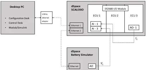
[image:5.612.45.289.174.308.2]The real-time equipment used was: dSpace Scalexio real time simulator with four Intel® Xeon® cores at 3.55 GHz and a DS2680 I/O module, a dSpace battery simulator and a desktop PC to run all the associated software. Figure 6 is a diagram of the equipment with the input and output connections as they were arranged at the IARC-HIL laboratory. It must be noted that the physical current signal is the Analog Output of the ECU3, the physical voltage signal is the Analog Output form the Battery simulator and, both signals are feed into the Analog Inputs of the ECU1.
Figure 6 HIL-Laboratory Equipment Setup
The analysis performed in the previous section was repeated with the Hardware in the Loop Setup and the results were exported to .CSV files. The SOC was plotted for the true and estimated scenarios as shown in Figure 7 where the estimated SOC follows closely the true signal. As the trends for the load voltage remain very similar despite the parameter changes, they were omitted in this section.
0.57 0.58 0.59 0.6 0.61 0.62 0.63 0.64 0.65
0 200 400 600 800 1000 1200 1400
Time (seconds)
[image:5.612.315.568.360.531.2]trueSOC estimatedSOC
Figure 7 True vs Estimated State of Charge
Tuning and robustness of the observer were verified in real time applying different scenarios: the initial observer SOC at 65% with the true system initial value of 20%, time convergence analysis and the observer against an aged model of a battery. Figure 8 shows the results for the first case. The graph includes the observer and nonlinear SOC as well as the difference between them. All the trends shown in the figures are similar to those obtained in the offline simulation; thus, validating real-time the SOC estimation strategy.
Figure 8 HIL initial true SOC 20%
V. CONCLUSION
A non-linear model of a Lithium-ion battery was derived using a ECN with two RC pairs. Offline simulations in Matlab/Simulink were used to validate this model against a real world current profile. Next, a Linear Observer was designed to estimate the State of Charge and experiments were done to establish the robustness of the observer for different scenarios: when the initial conditions between the plant and observer were set unequal, convergence time and, to evaluate the observer against battery aging. These, were performed offline and repeated with the HIL setup where strong agreement between them is observed; thus, validating real-time the SOC estimation strategy. Using the model of a battery allows to verify real-time the accuracy of SOC
[image:5.612.44.300.473.596.2]estimation methods without having to use an actual battery in a test chamber. The benefits of this approach are: eliminating the risk associated with cycling the cell during charging and discharging at different temperatures, reducing the cost associated with using physical cells and, ensuring repeatability of the test since the model does not suffer degradation every time it is used. Additionally, degradation can be modelled by modifying the component parameters without having to cycle the cells which is costly and time consuming.
REFERENCES
[1] U.S. EPA. Integrated Science Assessment for Oxides of Nitrogen Health Criteria (Second External Review Draft, 2015), U.S. Environmental Protection Agency, Washington, DC,
EPA/600/R-14/006, 2015. [Online]. Available:
http://cfpub.epa.gov/ncea/isa/recordisplay.cfm?deid=288043. [Accessed: 21-Mar-2017].
[2] Statement on the evidence for the effects of nitrogen dioxide on health, Commitee on the Medical Effects of Air Pollutants, UK
Government, 2014. [Online]. Available:
https://www.gov.uk/government/publications/nitrogen-dioxide-health-effects-of-exposure. [Accessed: 30-Oct-2016].
[3] X. Chen, W. Shen, T. T. Vo, Z. Cao, and A. Kapoor, An overview of
lithium-ion batteries for electric vehicles, 2012 10th Int. Power Energy Conf., pp. 230235, Nov. 2012.
[4] C. D. Rahn and C.Y. Wang, Battery Systems Engineering. Oxford, UK:
John Wiley & Sons Ltd, 2013.
[5] Y. Xing, E. W. M. Ma, K. L. Tsui, and M. Pecht, Battery management
systems in electric and hybrid vehicles, Energies, vol. 4, no. 11, pp. 18401857, 2011.
[6] J. Warner, The handbook of lithium-ion battery pack design : chemistry, components, types and terminology. Michigan, USA: Elsevier, 2015.
[7] K. Uddin, S. Perera, W. Widanage, L. Somerville, and J. Marco, Characterising Lithium-Ion Battery Degradation through the Identification and Tracking of Electrochemical Battery Model Parameters, Batteries, vol. 2, no. 2, p. 13, 2016.
[8] P. Weicker, A systems approach to lithium-ion battery management. Boston : Artech House, 2014.
[9] M. A. Hannan, F. A. Azidin, and A. Mohamed, Hybrid electric vehicles and their challenges: A review, Renewable and Sustainable Energy Reviews, vol. 29. pp. 135150, 2014.
[10] M. U. Cuma and T. Koroglu, A comprehensive review on estimation strategies used in hybrid and battery electric vehicles, Renew. Sustain. Energy Rev., vol. 42, pp. 517531, 2015.
[11] S. B. Peterson, J. Apt, and J. F. Whitacre, Lithium-ion battery cell degradation resulting from realistic vehicle and vehicle-to-grid utilization, J. Power Sources, vol. 195, no. 8, pp. 23852392, 2010. [12] I. Husain, Electric and hybrid vehicles : design fundamentals, 2nd ed.
Boca Raton, FL : CRC Press, 2011.
[13] M. Doyle and J. Newman, The use of mathematical modeling in the design of lithium/polymer battery systems, Electrochim. Acta, vol. 40, no. 13, pp. 21912196, 1995.
[14] C. M. Doyle, Design and Simulation of Lithium Rechargeable Batteries, PhD Thesis, University of California, Berkeley, 1995.
[15] J. Newman, K. E. Thomas, H. Hafezi, and D. R. Wheeler, Modeling of lithium-ion batteries, J. Power Sources, vol. 119, pp. 838843, 2003.
[16] A. Seaman, T. S. Dao, and J. McPhee, A survey of mathematics-based equivalent-circuit and electrochemical battery models for hybrid and electric vehicle simulation, J. Power Sources, vol. 256, pp. 410423, 2014.
[17] A. Fotouhi, D. J. Auger, K. Propp, S. Longo, and M. Wild, A review on electric vehicle battery modelling: From Lithium-ion toward Lithium-Sulphur, Renew. Sustain. Energy Rev., vol. 56, pp. 1008 1021, 2016.
[18] Y. Liu, S. Hong, and T. Ge, Real-Time Hardware-in-the-Loop Simulation for Drivability Development, in SAE Technical Paper 2017-01-0005, 2017.
[19] I. Cosadia, J. J. Silvestri, I. Papadimitriou, D. Maroteaux, and P. Obernesser, Traversing the VCycle with a Single Simulation -Application to the Renault 1.5 dCi Passenger Car Diesel Engine, in SAE Technical Paper 2013-01-1120, 2013.
[20] S. Klein et al., Engine in the Loop: Closed Loop Test Bench Control with Real-Time Simulation, SAE Int. J. Commer. Veh., vol. 10, no. 1, pp. 2017-010219, 2017.
[21] P. J. Shayler and A. J. Allen, Running Real-Time Engine Model
Simulation with Hardware-in-the-Loop for Diesel Engine
Development, SAE Tech. Pap. 2005-01-0056, vol. 2005, no. 724, 2005.
[22] K. Patil, M. Muli, and Z. Zhu, Model-Based Development and Production Implementation of Motor Drive Controller for Hybrid Electric Vehicle, in SAE Technical Paper 2013-01-0158, 2013. [23] M. Chen and G. A. Rincon-Mora, Accurate Electrical Battery Model
Capable of Predicting Runtime and IV Performance, IEEE Trans. Energy Convers., vol. 21, no. 2, pp. 504511, Jun. 2006.
[24] J. Marco, N. Kumari, W. Widanage, and P. Jones, A Cell-in-the-Loop Approach to Systems Modelling and Simulation of Energy Storage Systems, Energies, vol. 8, no. 8, pp. 82448262, 2015.
[25] B. Pattipati, C. Sankavaram, and K. R. Pattipati, System identification and estimation framework for pivotal automotive battery management system characteristics, IEEE Trans. Syst. Man Cybern. Part C Appl. Rev., vol. 41, no. 6, pp. 869884, 2011.
[26] H. He, R. Xiong, and J. Fan, Evaluation of Lithium-Ion Battery Equivalent Circuit Models for State of Charge Estimation by an Experimental Approach, Energies, vol. 4, no. 12, pp. 582598, Mar. 2011.
[27] H. Dai, X. Zhang, X. Wei, Z. Sun, J. Wang, and F. Hu, Cell-BMS validation with a hardware-in-the-loop simulation of lithium-ion battery cells for electric vehicles, Int. J. Electr. Power Energy Syst., vol. 52, no. 1, pp. 174184, 2013.
[28] S. Sepasi, R. Ghorbani, and B. Y. Liaw, Inline state of health estimation of lithium-ion batteries using state of charge calculation, J. Power Sources, vol. 299, pp. 246254, 2015.
[29] Y. He, W. Liu, and B. J. Koch, Battery algorithm verification and development using hardware-in-the-loop testing, J. Power Sources, vol. 195, no. 9, pp. 29692974, May 2010.
[30] G. L. Plett, II Extended Kalman filtering for battery management systems of LiPB-based HEV battery packs - Part 2. Modeling and identification, J. Power Sources, vol. 134, no. 2, pp. 262276, 2004. [31] C. M. Close and D. K. Frederick, Modeling and analysis of dynamic
systems. Chichester : Wiley, 1995.