Abstract—A novel incoherent transceiver design for optical
code-division multiple-access (OCDMA) system based on the (hybrid) frequency-polarization shift keying, so-called F-PolSK is proposed for the application in the passive optical networks (PON). In the system analysis we have considered the presence of (i) optical amplified spontaneous emission noise, (ii) electronic receiver noise, (iii) photo-diode shot-noise and (iv) multiple-access interference. The results revealed that the proposed architecture can easily accommodate a greater number of users with efficient power consumption. Furthermore, the system security is much enhanced due to two-dimensional advanced modulation in optical domain.
Index Terms—Frequency shift keying, optical CDMA,
polarization shift keying, prime code families
I. INTRODUCTION
ECENTLY, the multimedia-on-demand communication has remarkably increased requiring reliable and high data-rate services over a network. Passive optical network (PON) can be one of the best options to deliver the high bit-rate and high capacity services in very near future. Optical code-division multiple-access (OCDMA) provides multichannel communications over a single frequency band. Accordingly, signals must be designed to reduce mutual interferences. A power efficient high-order modulation technique based on polarization shift keying (PolSK) [1] can be considered as a solution to comply with the demands mentioned herein. Unlike traditional multilevel modulation techniques where the transmitted signals are represented as a two-dimensional (2D) constellation points, the PolSK exploits the degrees of freedom provided by the use of the three-dimensional (3D) states of polarization (SOP) of a fully polarized lightwave carrier as the information-bearing parameters. The received SOP fluctuations, caused by fiber birefringence, can be compensated at the decision processor as demonstrated experimentally in [2]. The receivers are implemented in a way to extract the Stokes parameters which completely characterize the received lightwave SOP. Ref. [3] and [4] has reported the advantages of the PolSK over OCDMA. On the other hand, frequency shift keying (FSK) modulation is attributed with high phase noise insensitivity and high power efficiency. The
The authors are with the Department of Electronic, Electrical and Computer Engineering, University of Birmingham, Edgbaston B15 2TT, UK (e-mails: [email protected] and [email protected] ).
advantages of FSK over OCDMA system has also been analyzed in [5]. The merits of hybrid optical frequency-polarization shift keying (F-PolSK) modulation solely in optical communication have been introduced in [6].
Here, we propose a novel design structure for the OCDMA transport network based on the two-dimensional array ( 2D-ary) F-PolSK modulation. This technique results in increasing distances between the modulated signal points on the Poincaré sphere [1], and hence reduced transmission power requirements. We also analyze the application of optical tapped-delay line (OTDL) as the incoherent OCDMA decoder. In our analysis we have assumed that the signal is degraded by (i) fiber amplified spontaneous emission (ASE) noise, (ii) electronic receiver noise (iii) photo-detectors (PD) shot-noise and (iv) multiple-access interference (MAI) caused by CDMA concept. However, an optical filter can be placed at the input of the receiver (or after the optical pre-amplifier, if needed) to reduce the ASE. Intensity-modulated incoherent systems are vulnerable in terms of interception, which can easily be broken by simple power detection, even without any knowledge of the code. Whereas by using 2D advanced modulation (i.e. F-PolSK) with flexible spreading code-length, the security can also be well improved.
For optical signature sequences, we have used a coding scheme based on a new spreading code referred to double-padded modified prime code (DPMPC). It has flexible properties and been extensively introduced and employed in pulse-position modulation (PPM) [7], in overlapping PPM [8] and in coherent schemes [9]-[11]. There has been a considerable shift of interests from coherent scheme to constant-power-envelope incoherent scheme on the part of both research and industry, due to its (i) simple architecture, (ii) cost effectiveness, (iii) high immunity to laser phase-noise, and (iv) insensitivity to self- and cross-phase modulations caused by the fiber nonlinearity.
The proposed transmitter configuration is introduced in the following section. The receiver structure and its analysis are studied in section III. The overall architecture performance is presented in section IV. Finally the study is concluded.
II. TRANSMITTER ARCHITECTURE
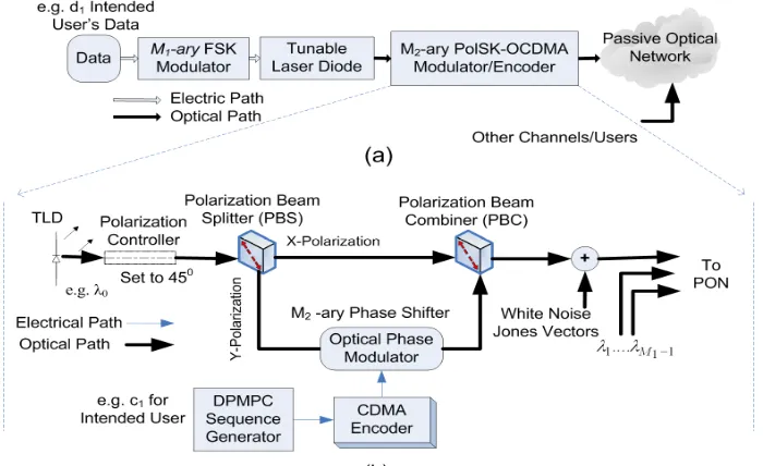
The 2D-ary F-PolSK transmitter is shown in Fig. 1a. It consists of FSK modulator with a tunable laser diode (TLD)
Hybrid F-PolSK Transceiver Architecture for
CDMA-PON
M. M. Karbassian,
Member, IAENG
and H. Ghafouri-Shiraz
which allocates M1symbols (
k
1=
log
2M1bits per symbol) to the correspondingM
1 wavelengths.The PolSK-OCDMA modulator is depicted separately in Fig. 1b. Each wavelength from the TLD, denoting the FSK modulated signal, is initially (linearly) polarized and set to
45
°for simplicity through polarization controller at the beginning of the PolSK modulator. The wavelengths then enter the PolSK-OCDMA modulator. The signal is M2−ary PolSK modulated whereM
2denotes number of the lightwave SOPs (k
2=
log
2M2bits per SOP), and CDMA encoded by means of the DPMPC spreading sequences.At the transmitter output and a given reference plane
(
x
ˆ
,
y
ˆ
)
normal to the direction of propagationzˆ, the transmitted lightwave over PON during
M
symbol intervals can be written, in the complex form as:∑ ∑
= =
− −
+ =
≤ ≤ =
M m
s T s m m c m
m M
m s
m m m
mT t u mT t f f j p
MT t t
v t v
1
) (
1 )
( 2 1
) (
2 1
) ( ] ) )( (
2 ( exp[
0 ) ( )
(
π
(1)
whereTsis the symbol interval,
m
1=
1
,
2
....,
M
1,m
2=
1
,
2
....,
M
2.)
(
) (2
1
t
v
mmm is the complex transmitted signal during them
thsignaling interval, ( )2 m m
p
is the 2D vector that gives the signal amplitudes and phases over xˆ and yˆdirections. fc is the carrier frequency with offsets of ( )1 m m
f (increment or decrement) representing the assigned frequency from the TLD.
) (t
uT is a rectangular pulse of unit amplitude. It is shown in [6] that the frequency tones orthogonality can be satisfied when the minimum frequency separation between any adjacent
frequency tones is ∆f =1Ts. Thus, ( )
1 m m
f takes values from
the set 11
1 )
(
1
/
2
}
{
r
mm∆
f
Mm= , where ( ) 1 11
2
m
1
M
r
mm=
−
−
. This makes the complex correlation coefficient value between two different frequency-polarization modulated signals ‘zero’ (i.e. orthogonal).In (1), ( )
2 m m
p
denotes the transmitted signal amplitudes and phases over the orthogonal xˆ andy
ˆ
channels during theth
m
signaling interval, given by:T m m y j m
m y m m x j m m x T m m y m m x m
m p p a e a e
p
=
=
) (
2 ) (
2 ) (
2 ) (
2 )
( 2 ) (
2 ) (
2
θ θ
(2)
where ( )
2 m m x
a
, ( )2 m m y
a
and ( )2 m m x
θ , ( )
2 m m y
θ are the amplitudes and phases of the
(
x
ˆ
,
y
ˆ
)
-components of the lightwave. The discrete random sequences 21 2 ) (
2}
{pmm Mm = and 1 1 1 ) (
1 } {rmm Mm= are stationary, independent and represent the source symbol sequences. Moreover, ( )
2 m m
p determines the SOP of the fully polarized lightwave given in (1) during the
m
thsymbol interval that is corresponding to symbol numberm
2.The electromagnetic wave ( )
(
)
21
t
v
mmm consists of two sets of2D-ary signals. The signals in each set are uncorrelated and orthogonal (i.e. orthogonal frequencies and SOP), and all the
2 1 2
1 M k k k
M
M = × → = + signals have the same time duration. Now, the data source emits a data symbol from a set of
M
symbols everyT
s=
k
.
T
b seconds, whereT
b is the bit duration. [image:2.595.125.475.91.305.2]The SOP is described using
(
( ))
2 3 ) (2 2 ) (
2
1 , ,
m m m m m
m S S
S as Stokes
parameters. Each of which is determined by the amplitudes
) (
2 m m x
a and ( )
2 m m y
a plus phase differences ( )
2 ) (
2 )
( m
m x m m y m
θ θ
θ = −
∆ of
the
m
thsymbol. These Stoke parameters and their relations have been discussed in [1].The average number of photons representing the energy of the transmitted multistate polarized lightwave over PON is directly proportional to other parameters, as:
2 3
1 ) (
2 )
( 2
0 ∑
=
=
i m m i m
m S
S (3)
where s
m s m
m E T
S
2 ) (
2
0 = is the fourth Stokes parameter
representing the transmitted optical waveform power with energy of
2
m s
E . Therefore, only three out of four Stokes parameters are mutually independent.
Due to the fiber-optic nonlinearity, it is very convenient to generate lightwaves with the constant power envelop. If all electromagnetic signals are transmitted on the same power level (i.e. ( ) 0
2
0 S
Sm
m = or equivalently,Esm2 =Es) and have the same carrier frequency, then they can be assumed as the vectors with the form of
3 ) (
2 3 2 ) (
2 2 1 ) (
2 1 ) (
2 S sˆ S sˆ S sˆ
S m
m m
m m m m
m = + + . These
vectors are allocated on the surface of the Poincaré sphere with a constant radius of S0 [1]. As a final point, the F-PolSK modulated and CDMA encoded lightwave is transmitted over PON as discussed and shown in Fig. 1.
III. ANALYSIS OF RECEIVER ARCHITECTURE A. Receiver Configuration
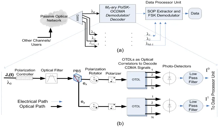
The front-end of the 2D-ary F-PolSK-OCDMA receiver for application in PON is initially with frequency selective arrayed waveguide grating (AWG), as illustrated in Fig. 2a. Here, the AWG is assumed ideal so that no interference between adjacent wavelengths occurs. The wavelengths assigned to the symbols at the transmitter are denoted as 1
1 1 0
,
λ
....
λ
M −λ
.Each wavelength (after AWG) enters the PolSK demodulator and OCDMA decoder, displayed separately in Fig. 2b, to indicate the Stoke parameters from each wavelength. Thereafter, the symbol SOPs are extracted based on Stokes parameters in the data processor unit, where the FSK part of the signal is also demodulated. The FSK detector determines the part of symbols which were used to generate the frequency tones
{
}
11 1
M 1 m ) m ( m
f
= in every symbol interval m.In Fig. 2b, the application of optical tapped-delay lines (OTDL) which are used as the optical correlator in incoherent OCDMA decoder is illustrated. The delay coefficients in OTDLs are designed in such a way to make them perform as CDMA chip-decoders at each wavelength filtered through AWG. It is observed from Fig. 2b that OTDLs outputs contain
N-chip pulses (where N equals code-length,P2+2P) that can be assumed as a parallel circuit of many single photo-detectors (PD). The currents are added up and no interference between the OTDLs pulses is possible. The signals are photo-detected to generate the electrical currents shown asI0 , I1in Fig. 2b denoting the upper and lower branches respectively. They are
[image:3.595.86.503.95.336.2]then ready for SOP and finally data extraction in the data process unit.
Since the balanced-detection is used for binary systems and we consider multiple levels (M2−ary) polarization modulation, the receiver structure in Fig. 2b is proposed for higher-order modulations. Accordingly, the total current of the upper branch (i.e. including all chip currents) can be obtained as:
(
)
∑ ∑ = = − − + + ℜ = N n Ki xi yi i i c xi yi c E t E t d tc t nT E t E t
nT c I 1 1 2 2 2 2
0 ( ) () () () ( )( () ())
4
(4) where
ℜ
denotes responsivity of PD andExi(t),Eyi(t) are the orthogonal(
xˆ,yˆ)
-components of received linearly polarized electric field ofi
thuser, di(t) is the data signal with symbol duration of Ts, ci(t) is the N-chip code sequences signal with chip duration of Tc anddi(t),ci(t)∈{0,1}. The electric current,0
I
contains the signal intensity generated at the upper branch of the modulator at the transmitter, defined by) ( ) ( 2 2 0 t E t E
Pi = xi + yi and the linear polarized information part generated in lower branch of the modulator at the transmitter (see Fig. 1b), defined byPi1 =Exi2(t)−Eyi2(t). Hence, the total current,
I
0(the same as lower currentI
1) can be rewritten as:(
( ) ( ))
() ) ( 4 1 1 0 10 c nT P d t c t nT P n t
I K i i c i i i N n
c + − +
ℜ
=
∑
∑
= =
(5) where
n
(
t
)
represents the filtered Gaussian noise with equal variance ofσ
n2(t) that includes: (i) the PD shot-noise with electric current variance of iav2 =2eiBowherei
av is the average photo-current; (ii) optically filtered ASE noise with variance of ASE N0Bo2
2 =
σ whereN0is the (unilateral) power spectral density (PSD) of the white ASE noise arriving at each polarization and also
B
o is the optical filter bandwidth; (iii) electronic receiver noise current (i.e. thermal noise) at the low-pass filter with variance of b elLP B R T k . 2 2 =
σ where
R
is thefilter direct-current (dc) equivalent impedance,
T
the absolute temperature and kb the Boltzmann constant, Bel the electronic filter bandwidth. Thus variance of additive noise of)
(
t
n
can be represented in total as:2 2 2 2
)
(t ASE LP
n i σ σ
σ = + + (6) The current I0 in (5) can be modified regarding first user (#1) as the intended user by further calculations as:
) ( ) ( ) ( ) ( 4 ). ( ) ( ) ( 4 ) ( 4 1 2 1 1 1 1 1 1 1 0 1 0 t n P t d nT t c nT c P t d nT t c nT c nT c P I i i K
i i c
N n c N n c c N n c + − ℜ + − ℜ + ℜ = ∑ ∑ ∑ ∑ = = = = (7)
The first term in (7) is the dc current that needs estimation and removal. The second term represents the intended data
mixed with its polarization and assigned spreading code auto-correlation (DPMPC [7], [8]). While the third element assumes the co-channel interference (i.e. MAI) caused by other transmitters and the last term exhibits the noise.
Hence, the system signal-to-noise ratio (SNR) with respect to the interference and the noise can be obtained as:
2 ) ( 2 1 2 1 2 1 1 1 1 1 ) ( ) ( ) ( 4 ). ( ) ( ) ( 4 t n i i K
i i c
N n c c N n c P t d nT t c nT c P t d nT t c nT c SNR σ γ + − ℜ − ℜ = = ∑ ∑ ∑ = =
= (8)
Now, according to the DPMPC properties [8], we have: 2 ) ( ) ( 1 1 + = − ∑ = P nT t c nT c c N n c (9) which is DPMPC auto-correlation and P is a prime number. By defining the variable
X
lias the DPMPC cross-correlation value:) ( ) (
1 i c
N
n l c
li c nT c t nT
X = ∑ −
=
(10) Its probability density function (PDF) can be derived from the independent values of random variable
X
li. The in-phase cross-correlation value of DPMPC [8] is either ‘zero’ or ‘one’ depending on whether the codes are in the same group or from the different groups. Obviously, the ‘zero’ value does not cause the interference due to perfectly orthogonal sequences, while the ‘one’ value causes the interference which is only among intended user and (P
2−
P
) users from the different groups (i.e.P2whole sequences (users) and P sequences from the same group of intended user which are orthogonal [10]). As, the cross-correlation values are uniformly distributed among interfering users, thus the PDF of w, realization ofX
li, is: P P i i w P − == ) 2
( (11) where
P
(
w
=
i
)
is the probability that w assumes the value i(the number of actively involved users in the transmission). Therefore, by substituting (9) and (11) into (8) and further simplifications, the system SNR can be obtained as:
2 2 1 1 2 1 2 2 ) ( 2 2 ) 2 ( ). ( 16 ) 2 )( ( 2 ) 1 )( 2 ( 1 ) ( ) ( + ℜ + + − − + = = P S t d P P P K K K K SNR t n σ γ (12) Note that: 0 2 ) ( 2 2 1 1 2 1 2 / 16 ) 2 ( ). ( ) 1
( d t S P E N
SNR =γ=ℜ + σnt = b (13)
is the single-user SNR where
E
b is the energy of one bit and0
N is the noise PSD. Expression (12) is one of the main results of this paper as it represents the system SNR of polarization-modulated OCDMA signaling.
B. Analysis of the Error Probability
By assuming that ( ) ( )
2
1 t
correct decision at the FSK demodulator (correct symbols carried by the correct wavelength) can be expressed as:
1 1 2
2 1 2
m m
m m
N N E
m m s m
≠ =
+ =
λ (14)
whereEsis the symbol energy and
{
}
1 1 M m mN = is independent, zero mean, Gaussian noise random variable. The correct decision is made if and only if
1 m
λ
in the decision rule ofary
M
1−
FSK satisfies:{ }
1 1M 1 m m 2
m
=
max
λ
=λ
(15) Also it is assumed that the received estimated noisyparameters
(
)
1 3 1 2 1 1
1 m , m, m
m R R R
R = are in the decision region of the un-noisy transmitted parameters
(
)
2 3 2 2 2 1
2 m , m , m
m S S S
S = .
Based on the maximum likelihood (ML) decision rule introduced in [2] and assuming that all possible transmitted vectors
{ }
Sl Ml=12 are equipower and equiprobable, then the decision metric is implemented as:2
1 1
2 2 1
) ( max
) (
M
l l l S m R m
m S m
R RS f RS
f
=
= (16)
where ( )
1Sl l
m
R RS
f , for l=1,2....,M2 is the conditional PDF of the estimated noisy Stokes vector
1
m
R given that
S
lis transmitted. This PDF was already given in spherical coordinates(
ρm,θm,φm)
in [1]. Referring to the ML rule particularly2
m
S was chosen as the transmitted vector when it satisfies:
{
}
21 1 2
1. max .
M l l m m
m S R S
R
=
= (17)
In the absence of noise, the index m in (15) and l in (16) should be equal to m1and m2 of ( ) ()
2
1 t
v m m
m respectively. The probability of the correct decision for the system is then equal to the probability that satisfies (15) times the probability that satisfies (17) conditional to (15), given by:
{ }
{
}
{ }
= =
×
= =
= =
=
1 1 2
1 2 1 1 2
1
1 1 2
1
max .
max .
Pr
max Pr
M m m m
M l l m m
m
M m m m
c
S R S
R P
λ λ
λ λ
(18)
The first probability in (18), is the probability that a correct decision is made on the transmitted frequency at the FSK demodulator shown in Fig. 2b. Its PDF has been discussed in [6].
The second probability in (18) is the probability that the transmitted SOP is correctly chosen at the data processor unit shown in Fig. 2a, as well as the correct decision is made on the transmitted frequency at the frequency demodulator. Since these two processes are independent, the probability of correct detection is equal to the PDF of M2−PolSK modulation. This PDF was also evaluated in [1] for some regular equipower polarization constellations.
IV. NUMERICAL DISCUSSIONS
In this section, the bit-error rate (BER) probability as a function of number of simultaneous users (K) with different single-user SNR (as shown by Sdb on graphs) is presented. The numerical results of the proposed architecture are introduced in Figs. 3 and 4.
Advantages of polarization and hybrid modulations over other modulations e.g. FSK or DPSK have already been discussed in [1], [2] and [6] for comparison purposes. Therefore, only the proposed architecture evaluation is demonstrated as it comparably outperforms.
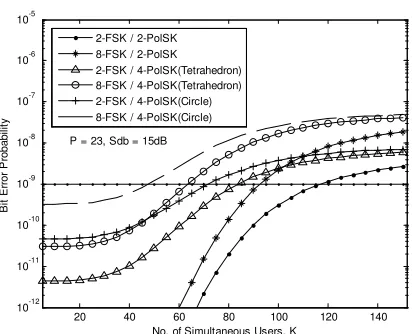
Figure 3 explains the performance of the transceiver under conditions of P= 23, Sdb= 15dB and different
M
1−
ary
FSK with differentM
2−
ary
polarization constellations. It can be observed from Fig. 3 that binary FSK with binary PolSK enhances the system BER to compare with other multiple array combinations. BER=10−9is exposed as a reference. The 2-FSK / 2-PolSK configuration is able to accommodate 24% (i.e. 120 users, regarding P=23) of full-load simultaneous users20 40 60 80 100 120 140 10-12
10-11 10-10 10-9 10-8 10-7 10-6 10-5
No. of Simultaneous Users, K
B
it
E
rr
o
r
P
ro
b
a
b
ili
ty
[image:5.595.63.269.95.262.2]P = 23, Sdb = 15dB 2-FSK / 2-PolSK 8-FSK / 2-PolSK 2-FSK / 4-PolSK(Tetrahedron) 8-FSK / 4-PolSK(Tetrahedron) 2-FSK / 4-PolSK(Circle) 8-FSK / 4-PolSK(Circle)
Fig. 3. BER of various M1-FSK / M2-PolSK optical CDMA against K
20 40 60 80 100 120 140 10-12
10-10 10-8 10-6 10-4 10-2
No. of Simultaneous Users, K
B
it
E
rr
o
r
P
ro
b
a
b
ili
ty
[image:5.595.63.268.291.457.2]P=23, 2-FSK / 2-PolSK Sdb = 9dB Sdb = 11dB Sdb = 13dB Sdb = 15dB 10e-9
withBER=10−9. To compare the results with those in [4], the proposed design enhances the system capacity with even smaller code-length (i.e. 575 regarding P=23 [8] whereas 1023 in [4]). Accordingly, the proposed coding and architecture can also offer higher throughput as the spreading code is smaller than Gold sequences used in [4].
Furthermore, it is observable that increasing the system multiplicity (i.e. Mx-ary) grows the system complexity and also degrades the overall performance. That also increases the implementation expenses. However, they are still reasonable enough to accommodate certain number of users
regarding 9
10− =
BER .
The 2-FSK / 2-PolSK performance evaluation with respect to different single-user SNR (i.e. Sdb) is illustrated in Fig. 4 against K as the most convenient and realistic scheme to consider. It is recognizable that the system is also very power efficient in that the system capacity is doubled (from 60 to 120) at the cost of only 2dB from 13dB to 15dB.
V. CONCLUSION
The 2D-ary signaling is presented and spread over higher dimensional constellation which provides distant geometric positions. This F-PolSK-OCDMA signaling for the application in passive optical networks has constant envelope that makes the signals more robust to nonlinear fluctuations imposed by optical fibers. The receiver structure has been designed by the aid of OTDL as the CDMA-decoder. Its performance has been analyzed by considering the optical amplified spontaneous emission noise, electronic receiver noise, photo-detectors shot-noise and mainly the multiuser interferences. Finally, the derived results indicated that the binary combination of two modulations remarkably enhances the system capacity in that it can reliably and power-efficiently accommodate greater number of simultaneous users. The system security has also been improved in terms of interceptions or intrusions due to 2D advanced optical modulation.
REFERENCES
[1] S. Benedetto and P. T. Poggiolini, “Multilevel polarization shift keying: optimum receiver structure and performance evaluation”, IEEE Trans. on. Commu., vol. 42, no. 2/3/4, pp. 1174-1186, 1994
[2] S. Benedetto, R. Paoletti, P. Poggiolini, C. Barry, A. Djupsjoebacka and B. Lagerstroem, “Coherent and direct-detection polarization modulation system experiments,” in Proc. ECOC '94, pp. 67-71, 1994
[3] M. M. Karbassian and H. Ghafouri-Shiraz, “Novel PolSK-OCDMA transceiver architecture”, in Proc. WCE 2008 (ICEEE), pp. 415-419 [4] K. Iversen, J. Mueckenheim and D. Junghanns, “Performance evaluation
of optical CDMA using PolSK-DD to improve bipolar capacity”, in Proc. SPIE, vol. 2450 (Amsterdam), pp. 319-329, 1995
[5] M. M. Karbassian and H. Ghafouri-Shiraz, “Novel channel interference reduction in optical synchronous FSK-CDMA networks using a data-free reference”, J. of Lightw. Technol., vol. 26, no. 8, pp. 977-985, 2008 [6] M. M. Matalgah and R. M. Radaydeh, “Hybrid frequency-polarization
shift keying modulation for optical transmission”, J. of Lightw. Technol., vol. 23, no. 3, pp. 1152-1162, 2005
[7] M. M. Karbassian and H. Ghafouri-Shiraz, “Fresh prime codes evaluation for synchronous PPM and OPPM signaling for optical
CDMA networks”, J. of Lightw. Tech., vol. 25, no. 6, pp. 1422-1430, 2007
[8] M. M. Karbassian and H. Ghafouri-Shiraz, “Capacity enhancement in synchronous optical overlapping PPM-CDMA netwrok by a novel spreading code”, Proc. of GlobeCom 2007, pp. 2407-2411
[9] M. M. Karbassian and H. Ghafouri-Shiraz, “Phase-modulations analyses in coherent homodyne optical CDMA network using a novel prime code family”, in Proc. WCE’07 (ICEEE), pp. 358-362, 2007