Abstract—With the flexibility of engine management and
regenerative braking characteristics, Series Hydraulic Hybrid Vehicle (SHHV) has been an important research object of institutions and automotive manufacturers all over the world. In this work the series hydraulic hybrid model of a Truck Class II is established for both forward and backward simulation. Dynamic Programming methodology is applied to estimate an optimal-benchmark solution, in which fuel consumption of the vehicle is selected as the objective function, for the proposed system over a pre-selected driving cycle. A rule-based control strategy is utilized for a physical forward-facing Simulink model to predict the fuel economy improvement of the SHHV system. With different rules, the improvement can be up to 80% in comparing with a traditional hydrostatic control strategy and up to 60% in comparing with a high quality standard; while as, the results with Dynamic Programming technique are 112% and 88% respectively.
Index Terms- Dynamic-Programming, Hydraulic-Hybrid-
Vehicle, Optimal-Control, Rule-Based.
I. INTRODUCTION
ASOLINE depletion risks forecasting and environmental concerns are the main reasons that stimulate the development of a higher efficient transportation system nowadays. In 2009, more than 70% of the United States’ oil consumption is consumed by transportation sector in which the light-duty vehicles share an amount of 45% of the total consumption [1]. Hence improving the efficiency of light-duty vehicle fleet is one of the most effective approaches to reduce the dependency on oil.
As a short and mid-term solution hybrid vehicles have been aroused the concentration of researchers and manufacturer all over the world recently. In the recent past, most of commercialization effort has focused on hybrid electric vehicles (HEV). Several commercially available
Manuscript received December 08th
, 2012; revised January 10th
, 2013. (Write the date on which you submitted your paper for review.) This work was the National Science Council under Grant NSC 101-3113-E-006-008 and by Taiwan Automotive Research and Testing Center.
C. K. Chen is with the Department of Mechanical and Automation Engineering, Dayeh University, Changhua 51591, Taiwan (corresponding author to provide phone: 886-935-658-801; e-mail: [email protected]).
T. V. Vu is with the Department of Mechanical and Automation Engineering, Dayeh University, Changhua 51591, Taiwan (e-mail: [email protected]).
C. W. Hung is with the Department of Mechanical and Automation Engineering, Dayeh University, Changhua 51591, Taiwan (e-mail: [email protected]).
HEV are passenger cars and light truck application [2]. Recent research and study indicate that further advantage has been realized with hydraulic hybrid vehicle. It is observed that hydraulic pump/motor (P/M) units achieve a higher magnitude of power density than that of electric generator/motor [3]. Therefore hydraulic hybrid propulsion is interested for heavy vehicle applications [4]. With the development of modern technology, hydraulic bladder accumulators can accept high charging/discharging rates with above 95% of round-trip efficiency [5]. This feature allows hydraulic hybrid vehicles (HHVs) achieve higher fuel economy through the regenerative braking ability, especially when the vehicle is driving in a stop-and-go pattern or in urban areas. However, the drawback of this system is the low energy density property of hydraulic accumulator required a big volume to store the captured kinetic energy. As a consequence, it requires more space and adds a significant mass into the system. Hence, a compromise should be taken into account. In the view point of regenerative braking capability, the HHV is able to capture and reuse 70-80% of kinetic energy when the vehicle decelerates [6]. While as the HEV can only recover about 15% of braking energy due to the limitation of the charging current of electric battery [7]. Therefore HHVs can achieve a higher fuel economy improvement than HEVs do.
In all types of hybrid vehicle, the main function of supervisory controller is to coordinate multiple power sources to satisfy the power demand of the driveline with the minimum fuel consumption in the most convenient way. In general, control strategies of the hybrid propulsion systems can be classified into three categories included rule-based, semi-optimal, and global optimal. Among of them, the rule-based control strategy is a real-time implementable power management. In this kind of control strategy, several rules are used to determine the control output according to pre-set conditions. Most papers regarding rule-based control strategy for HHV have been used the State-Of-Charge (SOC) of accumulator as the sole state variable for engine power determination [8], [9], [10], [11]. The SOC is defined by(1).
min max min
(
acc) / (
)
SOC
p
p
p
p
(1)where pacc is the instantaneous pressure of accumulator, pmax
and pmin are its maximum and minimum working pressure
respectively. It is obvious that SOC can be varied from zero to 1 due to the charging and discharging characteristics of hydraulic accumulator.
Dynamic Programming (DP) is one of methodologies to find a global optimization solution for sequential or
System Modeling and Control Strategy
Development for a Series Hydraulic Hybrid
Vehicle
Chih-Keng Chen, Tri-Vien Vu, and Chih-Wei Hung
multi-stages decision problems. The algorithm searches for optimal decision, for example control inputs to power devices and corresponding state variables, at discrete points in a time sequence with chosen cost functions. DP has been shown to be a powerful tool for optimal control in automotive applications. It can be used to optimize powertrain parameters, gear shifting strategy in conventional vehicles [12], [13], [14] and for the control variables replied on torque split or power split factors in hybrid vehicles [2], [8], [15].
II. SYSTEM ANALYSIS AND MODELING
A. System Description
This paper proposes a configuration of SHHV for a Rear-Wheel-Drive 3.5 ton Light-Duty Class II Truck. The schematic and control signal path of the system is shown in Fig. 1. The specifications of the vehicle are listed in Table 1. In this configuration, Diesel Engine E is connected to hydraulic pump P1. P/M unit P2 is connected to the rear wheels through differential DF. High pressure accumulator
Acc functions as a secondary power source of SHHV system. The stored energy in Acc can be the recovered energy from vehicle deceleration or provided by Diesel Engine E.
In this system, the inputs of the Center Controller are the pedal position signal, the current measured data-vehicle angular speed, engine angular speed, and accumulator pressure. The outputs of this controller are the signals to activate or deactivate the sub-controllers: hydraulic valve, drive and frictional brake controller. In accordance with the inputs, the central controller outputs commands are depended on the applied control strategy which will be discussed later.
B. SHHV Discretized Model for DPM Application
Many excellent text books and papers have been published on the subject of DP theory and its applications. They provide evidence that DP is a powerful numerical method for solving optimal control problems. Main advantage of DP above other methods is that global optimal solution is guaranteed with any type of problem. The serious drawback of DP is the computational effort grows exponentially with the number of state variables and inputs of the underlying dynamic system. Bellman called this difficulty the “curse of dimensionality”. Since implementation of DP algorithm on a computer arises many numerical issues and requires much effort, a general dynamic programming Matlab function, dpm, is used in this work. The dpm function was presented by O. Sundström and L. Guzzella in [16] and has been applied successfully for different traditional optimal control problems and the optimal hybridization in hybrid electric vehicle as well [17].
The model of SHHV used for dmp is shown in Fig.2. The objective of DP application is to find out optimal power split factor u that will minimize the fuel consumption mf of the
engine. The SOC of hydraulic accumulator is selected as the model state variable. Since there is no power split device available for SHHV, the purpose of applying dpm is actually to estimate the optimal power provided by internal combustion engine. This optimal solution will be used when implementing forward-facing SHHV model with different rule-based control strategies in next section. The discretized model of SHHV is given below.
TABLEI VEHICLE SYSTEM PARAMETERS
Symbol Quantity Value
Vehicle
m Mass (Gross Weight) 3490 kg
Equivalent Rotation Mass Ratio 1.15
Af Front Area 2.5 m2 Cd Drag Coefficient 0.3
Air Density 1.2 kg/m3
idf Differential Ratio 4.875 fr Rolling Resistance 0.008
Tire 195/75R16 Engine
Model 4M42-4AT2
Piston Displacement 2977cc
Pe,max/e,pmax Max. Output 92 kW /3200rpm Te,max/e,tmax Max. Torque 294 Nm/1700 rpm
e,max Max. Speed 3700 rpm
Cylinders In-line 4 Cylinder/4 Stroke
Compression ratio 17:1
[image:2.612.314.543.189.632.2]Fuel System Common Rail Fig. 1 Schematic and Control Signal Paths of SHHV.
0 100 200 300 400 500 600 700
0 10 20 30 40 50 60 70 80
Time (s)
S
p
eed
(k
m
/h
)
10 - Mode
15 - Mode
[image:2.612.316.543.213.642.2]10 - Mode 10 - Mode
Fig. 2 Japan 10-15 Mode Driving Cycle.
TABLEII
JAPAN 10-15MODE DRIVING CYCLE INFORMATION
Symbol Quantity Value
Vehicle
Ts Time 660 sec.
S Distance 4.16 km
vmax Max. Speed 70 km/h va Average Speed 22.68 km/h
In this work, Japan 10-15 Mode Driving Cycle is selected as the driving test for proposed SHHV system. The speed profile and key statistical information of this driving cycle is shown in Fig.3 and Table 2 below.
With a given driving test cycle, at each time step k, the reference speed vk and acceleration ak are available. The
desired torque and speed of P/M unit P2 are estimated by (2) and (3) respectively.
2
2,
/ 2
/
P k k d f k r df
T
r
ma
C A v
f mg
i
(2)2,
/
P k
i v
df kr
(3)The definitions and values of above symbols are listed in Table 1. The actual displacement and flow-rate requirement of P/M P2 are estimated by equations (4) and (5).
2, 2,
/
,P k P k acc k
D
T
p
(4)2, 2, 2,
P k P k P k
q
D
(5)where pacc,k is the pressure of accumulator at stage k. At each
stage, when the value of x is chosen, the pressure of the accumulator can be estimated by (6) below.
, max min min
acc k k
p
x
p
p
p
(6)Total efficiency of hydraulic pump/motor is a function of its displacement, angular speed, pressure different and its working mode. In this work, the updated version of Wilson’s P/M theory with the constants and calibrated coefficients roughly matched the model used by EPA [6].
2, 2,
,
2,,
,P k
f D
P k P kp
acc k
(7)The desired power provided/absorbed by P2 then be obtained as below
2, 2, 2, 2,
P k P k P k P k
P
T
(8)Assumed that the gas compression is determined on the basis of the thermodynamics of ideal gas and the process is adiabatic, the volume of fluid at stage k can be estimated approximately by following equation.
1/, 0
1
0/
,n
f k acc k
V
V
p
p
(9)where V0 is accumulator size, p0 is air-charge pressure, n is
specific heat ratio, for adiabatic process n = 1.4. The fluid volume of accumulator is updated as
, 1 ,
sgn(
,)
,f k f k acc k acc k
V
V
P
q
T
(10)where T is the time step, Pacc,k is the desired accumulator
power which will be shown later. The sign function will results +1 when Pacc,k > 0 corresponding to the dis-charging
mode and -1 for Pacc,k < 0 in the charging mode of
accumulator, respectively. The charged/discharged flow-rate of accumulator is depended on the desired accumulator power as
, ,
/
,acc k acc k acc k
q
P
p
(11)As mentioned before, the power split factor is selected as the control input variable of the model. The factor
(
,1]
u
determines the accumulator power Pacc andengine-pump P1 power according to
,
.
2,acc k P k
P
u P
(12)and
1,
1
2,P k P k
P
u P
(13)The pressure and corresponding SOC of accumulator at next stage will be estimated as following
, 1 0
/ 1
, 1/
0n
acc k f k
p
p
V
V
(14) and
1 , 1 min
/
max mink acc k
x
p
p
p
p
(15)In this optimization, total efficiency of pump P1 is assumed to be a constant. Hence, the desired engine power is obtained as follow.
, 1,
/
1E k P k P
P
P
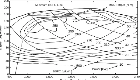
(16)When the engine power demand is specified, an engine map obtained from experiment will be used to estimate engine toque and engine speed which are allocated along the minimum BSFC line as shown in Fig. 4. The fuel consumption of the engine at stage k is estimated by interpolate the engine experiment data with the inputs of interpolation are engine torque and engine speed. The cost function is defined by
,
k k k f
g
x u
m
(17)with the final cost
0
0
0 x
x
( )
N
g
x
x
x
(18)C. Simulink Model of SHHV
Based on MATLAB/SIMULINK, the system is modeled as shown in Fig. 5. The component models are used directly from the built-in SimScape library. Details of vehicle specification, component selection and parameter setting for the proposed model can be found in [19]. The main function of the power management system is to apply a proper control strategy not only for ensuring safe operation regardless of the driver demand and vehicle states but also with minimum fuel consumption. Since the model of the IC Engine in Simscape Fig. 3 Backward Model of SHHV with Power Split Factor Concept.
600 1000 1,500 2,000 2,500 3,000 3,500 0
20 40 60 80 100 120 140 160 180 200 220
Engine Speed (rpm)
E
ngi
ne T
orqu
e (
N
m
) 50
500
Power [kW]
10 20 30 255
260
270
290 310
330 40
Minimum BSFC Line Max. Torque [N.m]
BSFC [g/kWh]
[image:3.612.320.550.590.721.2]250
does not provide method to calculate the fuel consumption of the engine, the mentioned experimental engine map is used in this model to estimate this important parameter. The fuel economy of a vehicle is evaluated by the traveling distance in mile per gallon fuel consumption (MPG) or the amount of fuel consumption for 100 km of traveling (L/100km).
III. SIMULATION AND RESULTS
A. Optimization of Power Management with DP
In the SHHV system, when the system configuration, component parameters and driving cycle are defined, the fuel economy strongly depends on the coordinating of two power sources to propel the system. As mentioned before, the objective of DP applying in this work is to find the optimal power split factor to minimize the fuel consumption of the SHHV over the whole driving cycle. The model equations are presented in previous part and can be summarized as
1
,
,
0,1,...,
1.
k k k k k
x
f
x u
x
k
N
(19)The optimization problem of minimizing the total fuel mass consumed over Japan 10-15 mode driving cycle can be stated as the discrete-time optimal control problem as below.
1
0
min
,
k k
N
f k
u U
k
m
u k
(20)
1
,
k k k k k
x
f
x u
x
(21)660 /
s1
N
T
(22)where mf.Ts is the fuel mass consumption at each time step.
When using the SOC of accumulator, a low power density energy storage device, as a state variable, if the time step is not small enough there may not exit any feasible solution. However, decreasing time step will increasing the time consumption of the DP program. Hence, it should be compromised. In this work, the time step is of 0.01s.
Physical constraints are given by equations from (23) to (27) below. If any constraint is violated, an infinite penalty is given to the cost function.
0
x
k
1
(23)_ min , _ max
E E k E
(24), _ max
E k E
P
P
(25)2,max 2, 2,max
P P k P
D
D
D
(26)1, 1,max
0
D
P k
D
P (27)In order to apply DP algorithm, the control variable u and the state variable x are needed to be discretized. Unlike in hybrid electric vehicle system, the state variable of the HHV system can be varied from 0 to 1. The lower-bound of control variable is depended on the size of engine and will affect the fuel consumption of the system due to the low power density characteristics of accumulator. In this simulation, the state variable and the control variable are gridded into 50 points and the lower-bound of the control variable are [-2, -1, 0]. Detail of structure and syntax of the dpm function can be found in [16].
Simulation results of applying dpm function for the discretized SHHV model with Japan 10-15 mode driving cycle are shown in figures from Fig. 6 to Fig. 9 below.
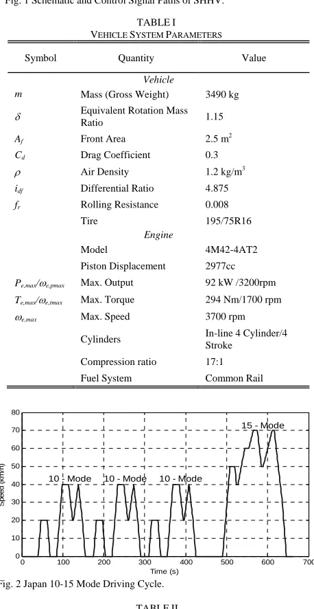
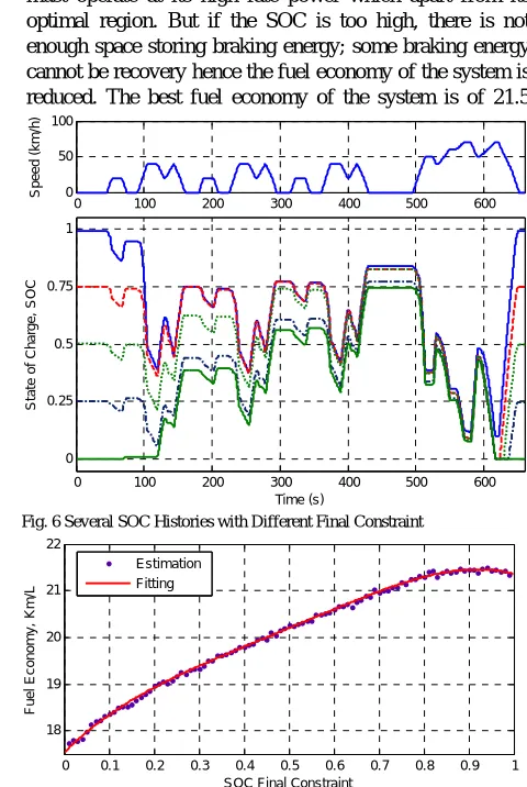
To estimate the fuel economy of the system, the final constraint of the SOC must be considered, the final value must be equal to the initial one. The example of applying this constraint to the system can be seen from Fig.6. This constraint implied that there is no pre-charged energy in the accumulator during the test. And the engine does not provide any unused energy stored in accumulator also.
The fuel economy of the system with different final constraint on the SOC is estimated and fitted as shown in Fig.7. The results show that when the initial SOC is small the energy assistant from accumulator is small then the engine must operate at its high rate power which apart from its optimal region. But if the SOC is too high, there is not enough space storing braking energy; some braking energy cannot be recovery hence the fuel economy of the system is reduced. The best fuel economy of the system is of 21.5
0 100 200 300 400 500 600
0 50 100
S
p
e
ed (k
m
/h
)
0 100 200 300 400 500 600
0 0.25 0.5 0.75 1
S
ta
te
of
C
h
ar
ge,
S
O
C
[image:4.612.69.301.48.211.2]Time (s)
Fig. 6 Several SOC Histories with Different Final Constraint
0 0.1 0.2 0.3 0.4 0.5 0.6 0.7 0.8 0.9 1
18 19 20 21 22
SOC Final Constraint
F
ue
l E
c
on
om
y
,
K
m
/L
Estimation Fitting
Fig. 7 The Relationship between Fuel Economy and Final Constraint on System SOC
Drive Shaft
Vehicle Dynamic Scopes
Throttle
Crank-Shaft
IC Engine E
High Press. Acc.
P1_P
P1_T
Low Press. Acc. P2_P
P2_T
Hydraulic Valve Mec_Brk Throttle
P2_Dis P1_Dis
Fuel Economy Eng_Spd
P2_Dis P1_Dis
Throttle Acc_Press VehSpd
Disp
Shaft P
T
Enigne-Pump P1
Disp A B
shaft
Drive-Pump P2 Drive Cycle
Cmd
Spd
Pressure
Engine Speed Throttle
P1_Dis
P2_Dis
Mec_Brk
Controller
A1
A2
[image:4.612.301.541.363.721.2]Km/L if the initial and the final value of the SOC is about 90%.
The SHHV DP results from 480 to 660 second are shown in Fig. 8. Interestingly, the SOC can go down closely to zero, it means that the stored energy can be fully used at each vehicle start and the accumulator has enough space for effective regenerative braking. Besides, the whole braking energy over the driving test schedule is captured and reused. Mechanical braking system is not involved during the test.
It also can be seen that the operating power of the engine remain nearly constant even when the demand power is low or high. When the power demand is low, the exceeded power from engine is absorbed by the accumulator. When the power demand is high, extra power is assisted by the accumulator. As a result, the engine can operate at its high fuel efficiency region. In addition, avoiding highly transient operating of the engine and concerning its low energy density characteristic, the accumulator is only used to absorb the exceeded engine power during tracking phase but not charging directly. Hence, the power split factor is limited within zero and one.
In this work, the dynamic of IC engine has not concerned.
Hence the engine is controlled to operate along its minimum BSFC line perfectly as shown in Fig. 9. In the future, this problem should be considered and the transient engine operation must be involved in the objective function of the optimal controllers.
B. Rule-Based Control Strategy with Optimal Benchmark
As mentioned before, the main function of the power management system is to apply a proper control strategy not only for ensuring safe operation regardless of the driver demand and vehicle states but also with minimum fuel consumption. There are three controllers have been used in proposed system. The first controller determines the engine power demand based on the SOC in the accumulator. The second controller will control the operation of engine to meet the desired power with minimum specific fuel consumption. The third controller will control the displacement of the pump/motor P2 ensuring that the vehicle follows the desired speed profile. The first controller will used the results from previous optimization process using DP algorithm as the benchmark solution.
One of the advantages of hydraulic accumulator in comparing with electric battery is that the accumulator can charge and discharge with a very high frequency. Besides, the accumulator can be charged to the full state or discharged to the zero state. The full state is at which the pressure of the accumulator reach its highest working value and the zero state is at which there is no available fluid stored in accumulator.
In thermostatic control strategy, the first controller either uses the SOC of accumulator A1 or the driver’s command for determining engine ON/OFF state. If the controller only uses the SOC as the state variable, it is named Pure-Thermostatic mode. In this case, whenever the accumulator is depleted it will be charged by the engine until reaching the full state. In the Acceleration-Thermostatic mode, the accumulator will be charged whenever it is depleted and the acceleration of the vehicle is greater than zero. In the last case, the charging of accumulator will occur if the condition of SOC is met and the acceleration of the vehicle is greater or equal to zero. This case is named With-Idle-Thermostatic mode.
The benefit of the Pure-Thermostatic mode is the pressure in the accumulator being high most of time. Hence the high acceleration driving condition can be met under any situation. However, higher pressure also means smaller available space reserved for regenerative braking. Hence the efficiency of the system may be reduced. On the other hand, in the Acceleration-Thermostatic mode the energy buffer capable of accumulator may not be used, the engine operating points will be shifted apart from its optimal region due to the high power demand from driver. Inherently, With-Idle-Thermostatic mode is the best candidate since the engine can charge the accumulator when the vehicle is stand-still to ensure that the accumulator can function as a secondary power source for a hard acceleration and also have efficient space for braking energy recovery later.
The Optimal-Thermostatic control strategy originated from the idea that maintaining the SOC within a specific range will improve fuel economy by avoiding unnecessary energy conversion from charging accumulator using engine.
480 500 520 540 560 580 600 620 640 660
0 50 100
S
pe
ed (k
m
/h)
480 500 520 540 560 580 600 620 640 660
0 0.5 1
S
tat
e of
C
h
ar
ge
SO
C
480 500 520 540 560 580 600 620 640 660
0 0.5 1
Po
w
e
r S
p
lit
Fa
c
to
r,
u
480 500 520 540 560 580 600 620 640 660
-20 0 20 40
Po
w
e
rs
, kW
Pe Pacc Pdem
480 500 520 540 560 580 600 620 640 660
-50 0 50
Di
s
p
la
c
e
m
e
n
t
cm
3/r
e
v
Time,sec
Pump/Motor Pump
Fig. 8 SHHV DP results from 480 to 660sec. of Japan 10-15 Driving Cycle
600 1000 1,500 2,000 2,500 3,000 3,500
0 20 40 60 80 100 120 140 160 180 200 220
Engine Speed (rpm)
E
ngi
ne T
o
rq
ue (N
m
) 50
500
Power [kW]
10 20 30 255
260 270
290 310
330 40
Minimum BSFC Line Max. Torque [N.m]
BSFC [g/kWh]
250
[image:5.612.72.293.285.584.2]Engine Visitation Points
With a proper selection, keeping SOC at the pre-designed low level before braking event can also help to store the regenerative braking energy effectively. As in the Thermostatic control scheme, three mode of Optimal-Thermostatic control scheme were investigated. An example of Optimal-Thermostatic control strategy on the With-Idle mode under Japan 1015 Drive Cycle is shown in Fig. 10. It can be seen that the pressure of accumulator is maintained within 150bar and 200bar. When the high power demand occurs, the pre-charge energy in accumulator will be used to provide the exceeded power, hence the engine will not necessary to be shifted to the higher power region. Also, the pressure of accumulator is kept at low value before each hard deceleration event.
A summary of the effects of different control strategies over the performance and the fuel economy improvement of proposed SHHV system is given in Table III. The fuel economy improvement of the system was estimated with two different criteria. In the first criterion, the fuel economy of the system working on Hydrostatic was selected as the baseline to estimate the fuel economy improvement of the system with other control strategies; in the second criterion, the fuel economy of 11.42 Km/L was selected.
IV. CONCLUSION
In this work, DP optimal control technique has been applied for a discretized SHHV model and a physics-based forward-facing simulation model of a SHHV also has been established. The improvement of fuel economy of the proposed system has been investigated over Japan 1015 Drive Cycle with different control strategies.
Simulation results show that the fuel economy improvement of proposed system using rule-based control
strategy can be up to 80% in comparing with a traditional hydrostatic control strategy and up to 60% in comparing with MYs 2012-2016 standards. Global optimized Dynamic Programming power management has been applied successfully to provide a benchmark power management for the rule-based control strategies. With DP technique the results can be up to 112% and 88% respectively.
In the future, since the power split device in SHHV has not been available, it is necessary to take the engine speed, engine-pump displacement and pump/motor displacement as control variables into account for more reasonable and accuracy problem.
REFERENCES
[1] Curtis, C., (2011, July 29). President Obama Announces New Fuel Economy Standards [Online]. Available: http://www.whitehouse.gov/ blog/2011/07/29/president-obama-announces-new-fuel-economy-stan dards.
[2] Shan, M., “Modeling and Control Strategy for Series Hydraulic Hybrid Vehicles,” PhD. dissertation, Col. Eng. Toledo Univ., OH, 2009. [3] Backe, W., “Present and future of fluid power”, in Proc. Inst. Mech.
Eng. I J. Syst. Control Eng. Vol. 207, No 4, 1993, pp. 193-212. [4] Kim, Y.A and Filipi, Z., “Series Hydraulic Hybrid Propulsion for a
Light Truck-Optimizing the Thermostatic Power Management”, SAE Paper 2007-24-0080, Naples, Italy, 2007.
[5] Energy Protection Agency, “World’s First Full-Size Hydraulic Hybrid SUV,” presented at 2004 SAE World Congress, EPA420-F-04-019, 2004.
[6] Alson, J., Barba, D., Bryson, J., Doorlag, M., Haugen, D., Kargul, J., McDonald, J., Newman, K., Platte, L., and Wolcott, M., “Progress report on clean and efficient automotive technologies under development at EPA,” EPA420-R-04-002, United States Environmental Protection Agency, 2004.
[7] Panagiotidis, M., Delagrammatikas, G. and Assanis, D., “Development and use of a regenerative braking model for a parallel hybrid electric vehicle,” SAE International, Paper number 2000-01-0995, Detroit, MI, March 2000.
[8] Wu, B., Lin, C.C., Filipi, Z., Peng H., and Assanis, D., “Optimal Power Management for a Hydraulic Hybrid Delivery Truck,” Vehicle Syst. Dyn., Vol. 42, No. 1-2, pp. 23-40, 2004.
[9] Filipi, Z., Loucas, L., Daran, B., Lin, C-C., Yildir, U., Wu, B., Kokkolaras, M., Assanis, D., Peng, H., Papalambros, P., Stein, J., Szkubiel, D., and Chapp, R., “Combined Optimization of Design and Power Management of the Hydraulic Hybrid Propulsion System for the 6x6 Medium Truck,” Int. J. Heavy Veh. Syst., Vol. 11, pp. 371-401, 2004.
[10] Kim, Y. and Filipi, Z., “Series Hydraulic Hybrid Propulsion for a Light Truck - Optimizing the Thermostatic Power Management,” SAE Technical Paper 2007-24-0080, (2007).
[11] Tavares, F., Johri, R., Salvi, A., and Baseley, S., “Hydraulic Hybrid Powertrain-In-the-Loop Integration for Analyzing Real-World Fuel Economy and Emissions Improvements,” SAE Technical Paper 2011-01-2275, (2011).
[12] Kolmanovsky, I.V., Sivashankar, S.N., and Sun, J., “Optimal Control-Based Powertrain Feasibility Assessment: A Software Implementation Perspective,” in ACC 2005, pp. 4452-4457, USA, 2005.
[13] Lin, C.C, Peng, H., and Grizzle, J.W., “Control System Development for an Advanced-Technology Medium-Duty Hybrid Electric Truck,” SAE Technical Paper 2003-01-3369, 2003.
[14] O’Keefe, M.P., and Markel, T., “Dynamic Programming Applied to Investigate Energy Management Strategies for a Plug-in HEV,” presented at the Conf. EVS-22, Yokohama, Japan, 2006.
[15] Kim, Y.A., “Integrated Modeling and Hardware-In-The-Loop Study for Systematic Evaluation of Hydraulic Hybrid Propulsion Options,” PhD. dissertation, Dept. Mech. Eng., Michigan Univ., MI, 2008. [16] Sundström, O. and Guzzella, L., “A Generic Dynamic Programming
MATLAB Function,” in 2009 Proc. IEEE Control Appl. Intell. Control, pp. 1625–1630.
[17] Elbert, P., Ebbesen, S., and Guzzella, L., "Implementation of Dynamic Programming for n-Dimensional Optimal Control Problems with Final State Constraints," IEEE Transactions on Control Systems Technology, vol.PP, no.99, 2012.
0 100 200 300 400 500 600
0 20 40 60 80
Veh
ic
le
S
p
e
ed (
k
m/
h
)
Vehicle Speed Ref Vehicle speed
0 100 200 300 400 500 600
-1 0 1
Ve
h
ic
le
S
pee
d E
rr
or
k
m
/h
0 100 200 300 400 500 600
100 200 300
A
c
c
u
m
u
la
to
r
P
res
s
ur
e (
b
ar
)
0 100 200 300 400 500 600
-1 0 1
P
/M
N
o
rm
a
liz
e
d
Di
s
p
la
c
e
me
n
t
Time(s)
Fig. 10 System Behavior of the Optimal-Thermostatic Control Strategy.
TABLEIII
SUMMARY OF THE SHHVPREDICTED PERFORMANCE AND FUEL ECONOMY
IMPROVEMENT
No. Name Fuel
Economy [Km/L]
Fuel Economy Improvement [%]
Criterion 1 Criterion 2
1 Hydrostatic 10.15 - -
2 Thermostatic
2.1 Acceleration 12.01 18.33 5.17
2.2 Pure 12.71 25.22 11.30
2.3 With-Idle 13.28 30.84 16.29 3 Optimal-Thermostatic
3.1 Acceleration 16.36 61.18 43.26
3.2 Pure 17.79 75.27 55.78
3.3 With-Idle 18.13 78.64 58.76
[18] Pourmovahed, A., Beachley, N.H., and Fronczak, F.J., “Modeling of a Hydraulic Energy Regeneration System - Part I. Analytical Treatment,”AEME Journal of Dynamic Systems, Measurement, and Control, Vol. 114, No. 1 pp.155-159, 1992.