621
©IJRASET: All Rights are Reserved
Power Quality Improvement by Using DVR
Based On Fuzzy Logic Controller
Shaik Nasarvali1, Nelluri China Kotaiah2, 1, 2
First-Electrical and Electronics Engineering, First- RVR&JC College of Engineering
Abstract: Power quality is one of the major concerns in the present power system environment. The situations like-voltage dip/sag, swells, harmonic content etc and so on and its major effect on greatly susceptible loads are well known. To tackle these situations, custom power apparatuses are utilized. Dynamic Voltage Restorer (DVR) is a modified power apparatus that is utilized to enhance voltage stability i.e. to minimize the power quality problems in electrical power system network. The important parts of the DVR comprise of voltage source inverter (VSI), booster transformer, filter and a dc energy source. The principle of the DVR is utilized to inject the voltage in series and in synchronism with the standard voltages with a goal to compensate voltage influences. There is various control techniques used for the operation of dynamic voltage restorer. This paper presents the fuzzy controller technique for generation of switching pulses for inverter of dynamic voltage restorer. The control technique based on voltage reference signals, and the proposed system is designed in MATLAB software, results shows that the how dynamic voltage restorer is useful for power quality improvement in distribution system.
Keywords: Dynamic voltage restorer, Power quality, Fuzzy controller, Hysteresis voltage control.
I. INTRODUCTION
Now a day, because of large use of sensitive and nonlinear loads in electrical power systems and the rapid growth of renewable energy sources, the power quality problems are very important. The most regular power quality situations are voltage dip, voltage swell, and harmonic contents and so on. Because of the power quality disturbances, the many industrial consumers are strongly affected. With today's development towards deregulation and competition between utilities, the present issues of power quality are absolutely important.
Voltage dip is described as a short drop in voltage waveforms, brought on by a shortcoming on the power system network. The definition of voltage dip is dependent upon two parameters, size and duration. To improve power quality, custom power devices are used. In 1995, the concept of custom power is first explained by Hingorani [1].
The thought of custom power (CP) identifies with the utilization of electronic controllers for power system network. There are number of custom power units which are given below, Distribution Statcom (D-STATCOM), Dynamic Voltage Restorer (DVR), Unified power quality conditioner (UPQC), Active Power Filters, Battery Systems (BESS), Distribution Series Capacitors (DSC), Surge Arresters (SA), Uninterruptible Power Supplies (UPS), Solid State Fault Current Limiter (SSFCL), Solid-State Transfer Switches (SSTS) [2] and Static Electronic Tap Changers (SETC). The CPD devices are either connected in series or in shunt or combination of both. The aforementioned every unit has its particular profits and constraints.
A. The dvr is Recognized as Successful sort of Custom Power Unit Due to Its Following Advantages
1) It has capacity to manage the active power flow.
2) It has less cost compared with others.
3) It requires less maintenance.
4) It has higher energy capacity.
5) DVR is more minor in size and expenses less compared with the DSTATCOM, likewise DVR recompenses the voltage
dip,voltage swell, it can additionally included different features for example power factor correction and harmonics elimination [2].
622
©IJRASET: All Rights are Reserved
II. DYNAMICVOLTAGERESTORER
Dynamic voltage restorer is overall suited to secure susceptible or delicate load from short span voltage dips and swells. Whenever a short circuit happens in a power system network, a sudden voltage dip will show on nearby feeders. With a DVR introduced on a load feeder, the line voltage is restored to its normal level within the reaction time of a few milliseconds. Hence power interruption is avoided.
A. Design Considerations For DVR
A commonly used series connected DVR is normally outlined to boost the missing voltage into the line through a booster transformer. Its main purpose is to reduce the effect of voltage sag or swell. It can be also used for the reduction of harmonics. Following are the some considerations while designing the DVR [9].
1) Choice of the Power Switching Apparatus: Power electronics devices for the dynamic voltage restorer used at distribution level are MOSFETs or IGBT. When consider IGBTs, the MOSFETs are the very faster power switching apparatus. That means it has a higher Converter switching frequencies, because of higher switching frequencies the transient oscillations and harmonics (higher order) are eliminated.
2) Size of the Series Booster Transformer: The transformer size is relates with the saturation. To minimize saturation under all conditions, the coupling transformer utilized as a part of DVR must be estimated to handle anyhow double the standard steady-state flux necessity at most extreme rms injection voltage, without saturation. The total device cost is depends on the transformer cost. 3) Detection of Supply Side Transformer: The DVR must detect the supply side disturbances very accurately. It is the important task for the operation of DVR.
4) Proper voltage restoration: At the time of restoration, for the proper voltage injection the DC link voltage is maintained at appropriate level. For this purpose, the large or small DC capacitor bank can be used.
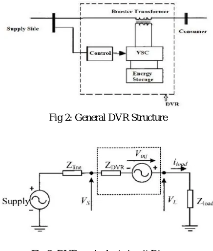
B. StructureofDVR
Following Figure 2 describes the general structure of dynamic voltage restorer [7].
[image:2.612.201.419.403.660.2]Fig 2: General DVR Structure
Fig 3: DVR equivalent circuit Diagram
The main components of dynamic voltage restorer are as follows [7]
623
©IJRASET: All Rights are Reserved
2) Harmonic filter: Harmonic filter is utilized to eliminate the harmonic contents which are generated in pulse width modulation. For that purpose passive filters are used.
3) Inverter: By using the inverter the dc voltage waveforms are converted into ac voltage waveform. A voltage source inverter is power electronics mechanism utilized to create the sinusoidal voltage at any needed magnitude, frequency and phase angle. It comprises of power storage unit and switching unit.
4) Energy storage device: It is used to supply the necessary energy for the generation of injected voltage to voltage source inverter via DC link.
5) Capacitor: DVR consists of a capacitor having large rating. In addition, it is used for stiff DC voltage for the input of an inverter.
C. Working of Dynamic Voltage Restorer
The working of dynamic voltage restorer is does not depends on fault type and any event that happened in the system. There are three different modes i.e. Protection mode, Standby mode & Boost mode-of operation of dynamic voltage restorer which are explained below [11].
1) Protection mode: If the current present on the load side exceeds a reasonable value because of short circuit on the burden and huge inrush current, the DVR could be separated from the system by utilizing the bypass switches and supplying a different path for current.
2) Standby mode (voltage injected by DVR is zero): In this mode of operation there is no switching of semiconductors occurs and through the converter the injection transformers low voltage winding is shorted. i.e. in this mode voltage injected by DVR is zero. 3) Injection/Boost mode: DVR injects a missing voltage through the injection transformer due to the recognition of a trouble in the input voltage. The location of DVR is either at the MV distribution level or at the LV-level close to a LV customer. It is explained below.
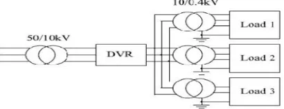
E. DVR Used for Medium Voltage Level
[image:3.612.212.417.434.513.2]The introduction of a DVR at the low voltage four- wire 400 V level is demonstrated in Figure 4. DVR is attached to the MV-level, it is used to protect a large consumer or a group of consumers. When a large Dynamic voltage restorer is inserted in medium voltage level it will only increases the supply impedance for a low voltage load.
Fig 4: DVR connected to MV-level
E. Attaching a Large DVR at MV-level has Following Advantages
1) The increased impedance inserted with a DVR seen by a LV load can be relative small if a large DVR is placed at the MV-level.
2) It has less cost when considering costs per MVA for protection. When only one large rating DVR is located at the medium
voltage level instead of small rated DVR units the total cost is also decreased.
F. It Has Few Disadvantages
1) Sometimes the losses in the medium voltage DVR will be too high.
2) Requires a high isolation level and the short circuit level are also high.
G. DVR used for low Voltage level
The introduction of a DVR at the low voltage four- wire 400 V level is demonstrated in Figure 5. The increase in impedance by addition of a small rated DVR can be important for the load to be protected from voltage dips. Thereby, the percent change in the impedance can be increased by several hundred percent.
It has certain advantages:
624
©IJRASET: All Rights are Reserved
2) It can be placed by the customer domain or by the utility domain.
3) The DVR can be under attack more specifically at voltage dip sensitive loads. It has some disadvantage:
[image:4.612.207.421.126.251.2]4) After insertion of DVR, the increase in impedance is large, which may affects the short circuit level and protection of the site.
Fig 5: DVR Connected to LV-level
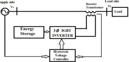
III.CONVENTIONALHYSTERESISVOLTAGECONTROLLER
[image:4.612.206.414.363.463.2]Following figure 6 explains the main control diagram of dynamic voltage restorer with hysteresis voltage controller. It mainly consists of three phase IGBT inverter, Energy storage, booster transformer and the hysteresis voltage controller. The hysteresis controller mainly requires two voltage signals, one is from supply side voltage signal and another is from booster transformer which is voltage injected by dynamic voltage restorer. The controller compares these two signals and according to these signals switching pattern is established [14].
Fig 6: Main control diagram
A. Structure of DVR with Hysteresis Voltage Control Technique
The control technique is based on voltage error and is non linear control method. It consists of a comparison between the output voltage and the tolerance limits (VH, VL )around the reference voltage, While the output voltage is between upper limit and lower limit , no switching occurs and when the output voltage increases to the upper limit (lower band) the output voltage is decreased (increased) [14].
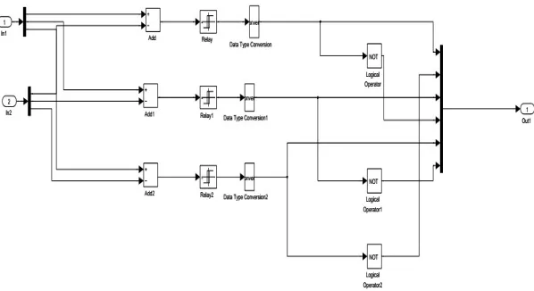
[image:4.612.200.421.580.725.2]625
[image:5.612.162.461.96.259.2]©IJRASET: All Rights are Reserved
Fig 8: Hysteresis voltage controller in matlab
IV.FUZZYLOGICCONTROLLER
The fuzzy logic controller unlike conventional controllers does not require a mathematical model of the system process being controlled. However, an understanding of the system process and the control requirements is necessary. The fuzzy controller designs must define what information data flows into the system (control input variable), how the information data is processed (control strategy and decision) and what information data flows out of the system (solution output variables) In this study, a fuzzy logic based feedback controller is employed for controlling the voltage injection of the proposed dynamic voltage restorer (DVR). Fuzzy logic controller is preferred over the conventional hysteresis controller because of its robustness to system parameter variations during operation and its simplicity of implementation. The proposed FLC scheme exploits the simplicity of the mamdani type fuzzy systems that are used in the design of the controller and adaptation mechanism.
Fig 9: Fuzzy logic controller
[image:5.612.141.483.417.582.2]626
[image:6.612.172.438.78.325.2]©IJRASET: All Rights are Reserved
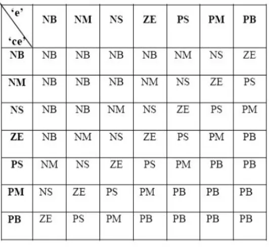
Table 1: Rule base for fuzzy logic controller
The set of fuzzy control linguistic rules is given in the Table 1. The inference mechanism in fuzzy logic controller utilizes these rules to generate the required output. The SIMULINK model of the proposed fuzzy logic controller is shown in figure 8.
Fig 10. SIMULINK model of proposed FLC
V. MODELLINGOFDVR
[image:6.612.96.517.383.639.2]627
[image:7.612.113.516.88.342.2]©IJRASET: All Rights are Reserved
Fig 11: Simulation of DVR using Fuzzy controller
VI.MATLAB/SIMULINKRESULTS
A. With Hysteresis voltage controller
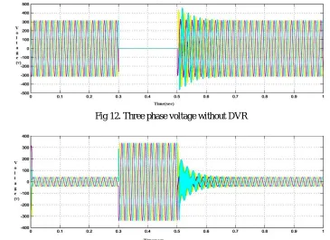
[image:7.612.117.482.453.718.2]The proposed power system consists of a three phase 440V/50Hz supply feeding two or more loads through distribution lines. A sudden three phase to ground fault generated in the system results in decrease in voltage.The above problem can be avoided by using load side compensation of DVR using voltage source inverter. Figure 12 shows the three phase voltage at the load point during three phase fault without DVR.
Fig 12. Three phase voltage without DVR
628
[image:8.612.133.479.75.207.2]©IJRASET: All Rights are Reserved
Fig 14. Three phase voltage waveform with DVR compensation
[image:8.612.204.421.267.479.2]From the figure 14 it is shown that the operation of DVR along with hysteresis controller maintains the load voltage at 90%.
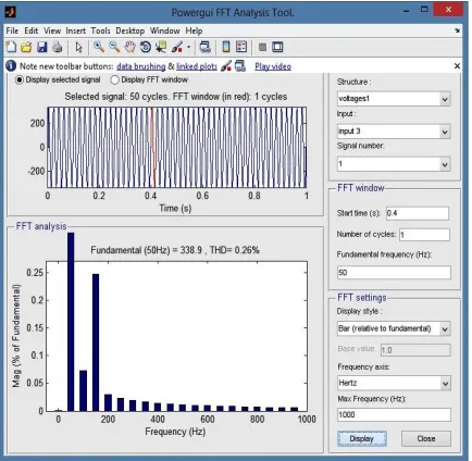
Fig 15. THD after compensation
From figure 15 the total harmonic distortion(THD) with hysteresis controller is 0.26%.
B. With Fuzzy logic Controller
[image:8.612.115.479.543.707.2]629
[image:9.612.131.481.78.203.2]©IJRASET: All Rights are Reserved
[image:9.612.135.480.236.363.2]Fig 17. Three phase voltage injected by DVR
Fig 18. Three phase voltage waveform with DVR compensation
From figure 18 When DVR and fuzzy controller are in operation the sensitive load is maintained at 98%.
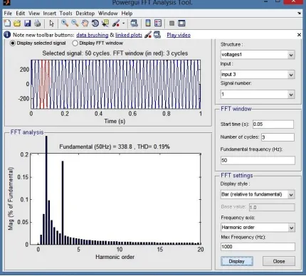
Fig 19. THD after compensation
From figure 19 the total harmonic distortion(THD) with hysteresis voltage controller is 0.19%. so harmonic injection decreased by 27%.From the above discussion it is well understood that the DVR along with fuzzy controller gives better performance when compared to other controller.
VII. CONCLUSION
[image:9.612.204.419.415.609.2]630
©IJRASET: All Rights are Reserved
fuzzy controller is modeled and the same is installed in the distribution system to provide required load side compensation. The simulation of the DVR along with the proposed controller is carried out using MATLAB/SIMULINK platform. The simulation results shows that the performance of voltage source inverter based DVR along with fuzzy controller is better compared to Hysteresis voltage controller.
VIII. ACKNOWLEDGMENT
A. Express my profound sense of gratitude to my guide, N.C.Kotaiah, Associate Professor, Department of Electrical Engineering,
R.V.R. & J.C. College of Engineering, Chowdavaram, for his systematic guidance and valuable advices. His encouragement and suggestions were of immense help to me throughout the tenure of my project work.
B. wish to express my sincere thanks to Dr.K.Chandra Sekhar, Professor and Head of the Department, Department of Electrical
Engineering, R.V.R. & J.C. College of Engineering, Chowdavaram, for providing me with all the necessary facilities for the work.
C. would like to take this opportunity to thank our beloved Principal, Dr.A.Sudhakar for providing great support to for giving me
the opportunity of doing this project and completing it in time.
D. would like to thank all faculty members of department of Electrical & Electronics Engineering for their direct and indirect
support for us in completing this project.
E. I also take this opportunity to thank my parents for their affection and encouragement.
F. Lastly, and most importantly, I wish to thank all my friends for being the surrogate family during the years I stayed here and for
their moral support.
REFERENCES [1] S. H. Hingorani “Introducing custom power” IEEE spectrum, vol.32 no.6 June 1995 p 41- 48 [2] Benachaiba Chellali, FERDI Brahim, “Voltage Quality Improvement
[3] Using DVR,” Electrical Power Quality and Utilizations, Journal Vol. XIV, No. 1, 2008
[4] M. Bollen. “Understanding Power Quality Problems, voltage sags and Interruptions.” IEEE press, 1999
[5] Ming Fang, Mister I. Gardiner, Andrew MacDougall, Granta A. Matheson, A novel series dynamic voltage restorer for distribution system, IEEE 1998 [6] C. Fitzer, M. Barnes and P. Green, “Voltage Sag Detection Technique for a Dynamic Voltage Restorer”, IEEE Trans. Industry Applications, Vol. 40(1), Jan.
2004, pp. 203 - 212
[7] Power Quality Enhancement Using Custom Power Devices by A. Ghosh and G. Ledwich. 2002. Kluwer Academic Publishers
[8] S. Choi, J. Li and M. Vilathgamuwa, “A Generalized Voltage Compensation Strategy for Mitigating the Impacts of Voltage Sags/Swells”, IEEE Trans. Power Delivery, Vol. 20(3)
[9] Nielsen, Newman, H. Nielsen, and F. Blaabjerg, “Control and testing of a dynamic voltage restorer (DVR) at medium voltage level,”IEEE Trans. Power Electronics. vol. 19, no. 3, pp. 806–813, May 2004
[10] J. G. Nielsen, “Design and Control of a Dynamic Voltage Restorer,” Ph.D. dissertation, Institute of Energy Technology, Aalborg Univ., Aalborg, Denmark, 2002
[11] Boonchiam P, and Mithulananthan N, “Understanding of Dynamic Voltage Restorers through MATLAB Simulation” Thammasat Int. J. Sc.Tech., Vol. 11, No. 3, July-Sept 2006