Road Power Generation
Nikhil Kachale1,Dhiraj Khond2, Mahesh Anandkar3,Prof. Arpita Shroff4 1, 2, 3
BE Student, 4Professor, Department of Electrical Engineering, University of Pune, JSPM’s BSIOTR, Wagholi, Pune, Maharashtra, India;
Abstract:This paper addresses, The extensive usage of energy has resulted in an energy crisis, and there is a need to develop
methods of optimal utilization, which will not only ease the crisis but also preserve the environment. The focus now is shifting more and more towards the conventional energy, which are essentially, non-polluting. In this paper we approach a new mechanism to generate power from speed bumper, because the number of vehicles passing over the speed bumper in roads is increasing day by day. This proposed system is to extract the kinetic energy of vehicle flow in the streets entitled as generating power from speed bumper through hydraulic mechanism. It is more efficient than other existing models, which enable to accommodate conventional, both in terms of balancing electricity supply and demand in energy across the global..
Keywords: Conventional energy, Rack and Pinion mechanism, Power generation, Speed bumper, vehicle flow, Generator, Inverter, Street Light.
I.INTRODUCTION
In this paper we discussed about the Road Power Generation. The automotive industry in India is one of the largest in the world and one of the fastest growing globally. India's passenger car and commercial vehicle manufacturing industry is the 4th largest in the world, with an annual production of more than 3.9 million units in 2017.We every day mesh up with these vehicles give us headache. But this mesh up could be answer of new type power generation. Road Power Generation (RGP) is one of the most recent power generation concepts. This device is engineered as a practical and useful alternative energy technology for generating clean electricity from the millions of vehicles on our roadways. Once fully optimized and installed, engineers anticipate that devices may be used to augment or replace conventional electrical supplies for powering roadway signs, street and building lights, storage systems for back-up and emergency power, and other electronics appliances, and even devices used in homes and businesses. This device converts the kinetic energy of the vehicles into electric energy. This is done by rack and pinion mechanism installed under the road, this mechanism take the stroke motion of the vehicles and convert it to the rotary motion by rack mechanism and it generates the electricity.
II. LITERATURE REVIEW
A. Road Power Generation, J.Mustafa, N.Fatima
The number of vehicles passing over the road is increasing day by day. A large amount of energy is wasted at the speed breakers through the dissipation of heat and also through friction, every time a vehicles passes over it. There is great possibility of tapping this energy and generating power by making the speed-breaker as a power generation unit. The generated power can be used for the lamps, near the speed breaker.
B. Electric Power Generation System by rack and Pinion Mechanism, Kiran Kolhe
The mechanism used in the assembly is rack and pinion mechanism. It converts reciprocating motion into rotary motion. Here, the rack is the element producing reciprocating motion and pinion rotates due to this reciprocating motion. The rack is displaced vertically due to the weight of the vehicle passing on the speed breaker and thus it reciprocates. As the rack reciprocates, it turns the pinion to rotate. The rack is the flat part which has teeth, while the pinion is a gear.[2]
III. PROBLEM STATEMENT
IV. METHODOLOGY
In this section, it was tried to understand the working principle of the RPG designed system its practical Implementation.
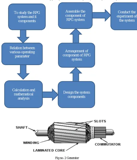
[image:2.612.83.540.101.637.2]Fig no. 1 Methodology
Fig no. 2 Generator
A. Generator
An electrical Generator is a machine which converts mechanical energy into electrical energy (or power). For this model a permanent magnet DC generator with drum type armature, wave winding is suitable which is shown in fig. The e.m.f induced in any parallel path in armature Due to spring tension, the exhausted oil is recycled back to the cylinder with the help of inlet control valve. Hence, the speed breaker gets back to its original position. So, if we implement one such speed breaker on a busy highway, we can able to tap maximum amount of electricity from the waste kinetic energy of a vehicle.
To study the RPG
system and it
components
Relation between
various operating
parameter
Calculation and
mathematical
analysis
Design the system
components
Arrangement of
component of RPG
system
Assemble the
component of
RPG system
Conduct the
experiment of
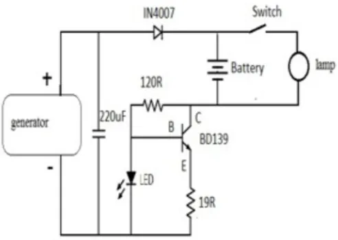
Fig no. 3 stabilizer circuit
B. Stabilizer Circuit
In order to store the electrical energy in battery, stabilizer is required. To design a stabilizer we need to consider the output current values. Battery is chosen according to the output power, which is generated from the proposed model. The following circuit is used for 6V, 1.2Ah battery. Based on the Ah value of battery resistor value should be altered in the below circuit, for proper charging. The higher charge current, the more critical the charge time must be checked. When faster charging is used, it is advisable to discharge the battery completely before charging. Using a charge current of 1/10 of the capacity will expand the lifetime of the battery. The charge time can easily be doubled without damaging the battery
Fig no. 4 Rack and Pinion
C. Rack And Pinion
Whenever the vehicle is allowed to pass over the dome it gets compressed with the help of spring and the rack which is attached to the bottom of the dome moves downward in reciprocating motion. Since the rack has teeth connected to gears, there exists conversion of reciprocating motion of rack into rotary motion of gears but the two gears rotate in opposite direction. By the use of ball bearings, one of the rotary motions is utilized to generate power.
D. Ball Bearing
A ball bearing is a type of rolling-element that uses balls to maintain the separation between the bearing races. It permits relative motion between the surfaces which are in contact while carrying loads. The relative motion between the components causes the balls to roll with little sliding. The ball bearing is used to reduce friction and transmit the motion effectively.
Fig no. 6 Sprocket
E. Sprocket
It is a profiled wheel with teeth that can mesh with a chain, or other perforated material. Sprocket is generally a wheel upon which radial projections engage a chain passing over it. Chain drive is used to connect the sprockets in order to transmit power. It is distinguished from a gear, that sprockets are never meshed together directly.
Fig no. 7 Spring
F. Spring
Spring is an element which possess elasticity and its function is to expand and contract to recover its original shape when it is loaded or unloaded. It changes its shape according to the load applied. It absorbs energy either due to shocks or due to vibrations. Springs are usually made out of hardened steel. Small springs can be wound from pre-hardened stock, while larger ones are made from annealed steel and hardened after fabrication.
G. Inverter
[image:4.612.208.399.601.713.2]A inverter is an electronic device or circuitry that changes direct current (DC) to alternating current (AC). A typical power inverter device or circuit requires a relatively stable dc power source hence the output of stabilizer circuit is given to the inverter.
H. Transformer
A transformer is a static device which increases the voltage from primary winding to secondary winding by principle of mutual inductance. It is use Faraday’s law of electromagnetic induction to transfer electrical energy from one circuit to another circuit.
I. Battery
It is a device which stores energy generated from the generator. The energy is stored in the form of chemical energy in the battery. This energy can be used as and when it is required
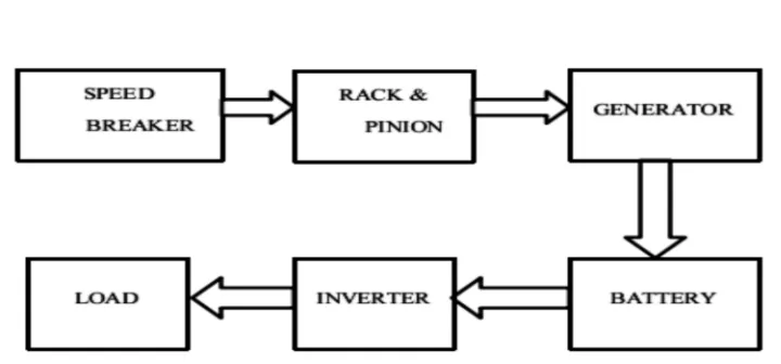
[image:5.612.122.482.196.364.2]V. BLOCK DIAGRAM
Fig no. 9 Road Power Generation
VI. ADVANTAGES OF ROAD POWER GENERATION
A. Power generation with low cost using non conventional energy sources
B. By using this method, electricity will be generated through out the year
C. Pollution free power generation
D. No need of manpower during power generation
E. Easy for maintenance and no fuel transportation problem
VII. RESULT
Total load = 360 Kg (Vehicle load + man weight)
Sr.No. Speed of vehicals (km/hr) Voltage generated (volts)
1 10 8.93
2 20 7.32
3 30 6.05
4 40 5.65
5 50 4.04
Table 1: Summary of Voltage generated versus speed of vehicles
Sr no. Load of man & Vehicals (kgs) Voltage generated (volt)
1 360 8.33
2 430 9.57
3 470 10.44
4 500 11.34
5 570 11.81
VIII. CONCLUSION
Road power generation is a new type of non conventional source of energy. This uses wasted energy of moving vehicles. It converts kinetic energy developed from moving vehicle to electric energy. It is possible answer for battery charging station and also for lightning of the street light, traffic signal, etc.
REFERENCES
[1] N. Fatima, J. Mustafa (2012), Production of electricity by the method of road power generation, Int. J. advances in Electrical and Electronics Engineering. [2] Kiran Kolhe(2017), Electric power generation system by rack and pinion mechanism, smt. Kashibai navale college of engineering, department of electrical
engineering.
[3] A. K. Singh, D. Singh, M. Kumar, et al. (2013), Generation of electricity through speed breaker mechanism, Int. J. Innovations in Engineering and Technology [4] V. Aswathaman, M. Priyadharshini, (2011), Every speed breaker is now a source of power, In: 2010 International Conference on Biology, Environment and