Grain Refinement of Aluminum Alloy Bar by a Modified RAP Process
for Semi-Solid Forming
Yongfei Wang
*, Shengdun Zhao and Chenyang Zhang
School of Mechanical Engineering, Xi an Jiaotong University, Xi an 710049, China
A modified Recrystallization and Partial Melting (RAP) process including Radial Forging (RF) and Semi-Solid Isothermal Treatment (SSIT) was proposed to refine the grains of 6063 Al alloy bar for semi-solid forming. The 6063 Al alloy bar (φ120 mm × 800 mm) was deformed by RF into a stepped shaft with different Area Reduction Ratios (ARRs) at the temperature of 300 C, and then the samples cut from both the central and peripheral parts of the RF-deformed bar were treated with SSIT at 630 C for 10 min. The effect of ARR on the microstructural evolution of semi-solid 6063 Al alloy was investigated. Results showed that, during the RF process, the microstructures of the samples became denser as the ARR increased. After SSIT, with the increase of ARR, the average grain sizes of both the central and peripheral parts were reduced and the spheroidization degrees of both the central and peripheral parts were improved. The variation tendency of grain size experienced three different stages: precipitous reduction, gentle reduction and unobvious change. Besides, the differences between grain sizes of the peripheral and central parts were gradually decreased with the increase of ARR. Additionally, the optimal process parameter for refining grains was 70% ARR at 630 C for 10 min. [doi:10.2320/matertrans.M2016271]
(Received July 29, 2016; Accepted November 16, 2016; Published December 26, 2016)
Keywords: aluminum alloy, grain refinement, recrystallization and partial melting (RAP) process, semi-solid, radial forging
1. Introduction
Compared with conventional casting and forging process-es, semi-solid forming offers significant advantagprocess-es, such as increased die life, reduced micro-segregation, and improved mechanical properties.1–3) The main requirement for metals to be shaped in semi-solid state is that they should exhibit a fine and spherical microstructure.4–6) Therefore, to obtain ide-al semi-solid microstructure, techniques such as mechanicide-al or electromagnetic stirring, mechanical vibration, spray deposition, cooling slope casting, strain-induced melt activa-tion (SIMA), recrystallizaactiva-tion and partial melting (RAP) are commonly used.7–12) Among these methods, SIMA and RAP might be two most widely used approaches owing to their low equipment costs.13) SIMA and RAP are similar with each oth-er including two stages which are deformation and semi-solid isothermal treatment (SSIT). However, SIMA is performed above recrystallization temperature while RAP below recrys-tallization temperature.14,15)
The deformation stage is the most critical stage in SIMA and RAP processes because it determines the grain size and uniformity of semi-solid microstructure16). Therefore, the grain refinement of alloys by different deformation methods has attracted much attention in recent years. Jiang et al.17) employed equal channel angular extrusion in SIMA to de-form AM60 magnesium alloy. They found that high-quality semi-solid billet can be prepared by five-pass equal channel angular extrusion and subsequent SSIT at 560 C for 15 min. Zhao et al.18) used cyclic closed-die forging in SIMA to pro-cess AM60B magnesium alloy. They observed that the fine microstructure can be prepared by four-pass cyclic closed-die forging and partial remelting at 580 C for 10 min. Chen et
al.19) introduced repetitive upsetting-extrusion into SIMA to deform AZ80 magnesium alloy. They reported that the solid grain was refined with the increase of the number of repetitive upsetting-extrusion passes. Moreover, an ideal sesolid
mi-crostructure could be obtained when the alloy was subjected to eight-pass repetitive upsetting-extrusion and then heated at 570 C for 5 min. Yan et al.20) proposed cross wedge rolling and cold compression in SIMA and pointed out that finer grains could be achieved through higher compression defor-mation. Wang et al.21) presented rolling deformation in SIMA to process ZCuSn10 alloy. They suggested that the fine and spheroidal grains could be prepared when the alloy with four-pass rolling deformation was heated at 875 C for 15 min. Chen et al.22) introduced accumulative plastic deforming into RAP to prepare semi-solid AM60 alloy. They noted that the accumulative plastic deforming process including upsetting, multi-axial forging, rolling and extruding was an effective method to obtain semi-solid AM60 alloy with fine micro-structures.
Although many deformation methods have been used in SIMA or RAP process to refine grains, the billet dimensions are severely limited by the insufficient capacity of the equip-ment, and the deformation efficiency is low because of the relatively complex deformation process. To our knowledge, radial forging (RF) is an effective method to produce relative-ly large billet with good deformation uniformity and high de-formation efficiency23). However, little attention has been devoted to the application of RF in SIMA or RAP processes.
6063 Al alloys are widely used in automotive, motorcycle and electronics because of their low density, high specific strength and stiffness and excellent damping capacity. How-ever, they are currently machined to parts from the wrought state with much waste. Semi-solid processing is a potential near-net shape technology for forming 6063 Al alloy but there has been little research reported in the literature. Therefore, in this study, a modified RAP method including RF and SSIT was proposed to refine the grains of 6063 Al alloy bar for semi-solid forming. The effect of ARR on microstructural evolution of semi-solid 6063 Al alloy was investigated, and the optimal process parameters for refining grains were ex-plored.
*
2. Experimental Procedure
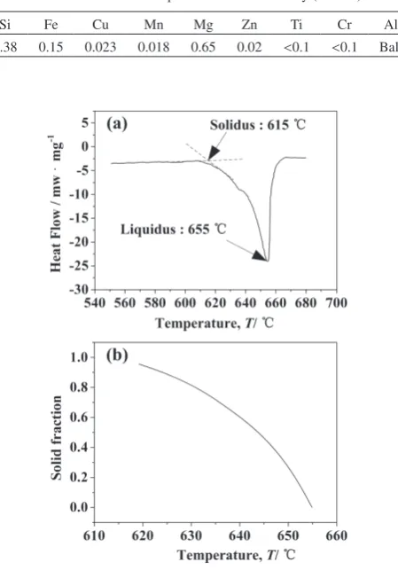
A commercial extruded round bar of 6063-T6 Al alloy (φ120 mm × 800 mm) was used as starting material, and its chemical composition is shown in Table 1. Differential scan-ning calorimeter (DSC) was used to determine the solidus and liquidus temperatures. The solidus and liquidus tempera-tures shown in Fig. 1(a) are 615 C and 655 C, respectively. The solid fraction versus temperature curve shown in Fig. 1(b) was obtained by the integration of the DSC curve. It should be noted that the practical value of solid fraction in micro-graph was not indicative of the solid fraction at a known tem-perature based on Fig. 1(b), which was attributed to short holding time and deposition of liquid phase.14,24)
From the process of RF shown in Fig. 2, the deformation in RF results from a large number of short-stroke pressing
oper-ations performed by the four hammer dies arranged circum-ferentially around the 6063 Al alloy bar. Meanwhile, the bar rotates and axially advances during the interval between suc-cessive strokes23). The deformation degree of the alloy after RF is expressed by
ψ=(A0−A1)/A0×100%
where ψ is the ARR; A0 and A1 are the cross sectional area of the initial bar and the RF-deformed bar, respectively.
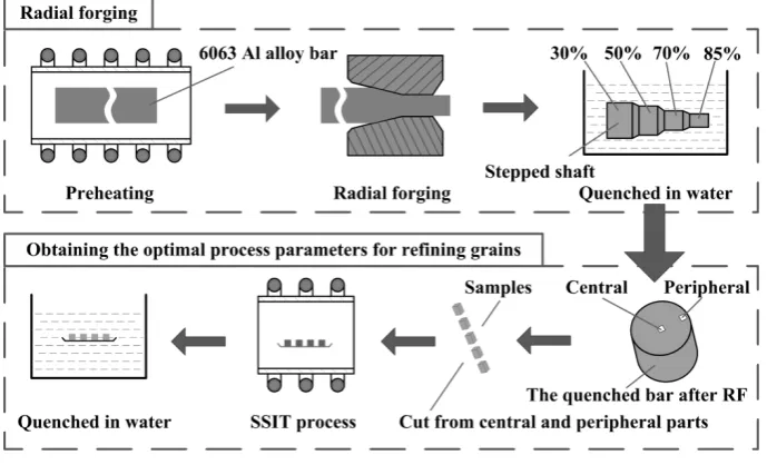
Figure 3 shows the process flowchart of the modified RAP. First, the 6063 Al alloy bar was preheated at 300 C for 90 min. Subsequently, the preheated bar was radial forged to a stepped shaft with different ARRs (30%, 50%, 70%, and 85%) and then the stepped shaft was quenched in water. According to Jiang et al.25) and Atkinson et al.26), this RF-deformed pro-cess could be classified as warm deformation below the re-crystallization temperature, which is the typical characteristic of RAP. Finally, fine and spherical grains can be prepared by further SSIT on the quenched bar with optimal ARR.
As shown in Fig. 3, in order to obtain optimal process pa-rameters for refining grains, samples cut from both the central and peripheral parts of the quenched bar with different ARRs were treated with SSIT. The specific experimental parameters of SSIT are shown in Table 2. During the process of SSIT, the samples were treated isothermally at 630 C for 10 min in the resistance furnace under a protective gas flow (Ar atmo-sphere), and the furnace temperature was controlled by a ther-mocouple placed next to the sample being treated. After SSIT, the samples were rapidly quenched in water to retain the mi-crostructure.
The samples for microstructure characterization were pre-pared by the standard metallographic technique, followed by etching in an aqueous solution of 5 vol% HF. The microstruc-ture was observed by using a Nikon optical microscope. The average grain size and shape factor of the solid grains were measured using a digital image analysis system. The average grain size (D) and shape factor (F) of solid grains were calcu-lated as follows:20)
D= N
N=1 4A/π /N
F= N
N=14πA/P
2 /N
where D, F, A, N and P are average grain size, shape factor, area, the number and perimeter of grain, respectively.
3. Results and Discussions
[image:2.595.57.282.300.622.2]3.1 Microstructure of starting material before and after SSIT
Figure 4 shows the microstructures of starting material from different parts. As shown in Fig. 4, the microstructures of both peripheral and central parts are mainly composed of elongated grains and intermetallic particles (appeared as small dots and long stringers). The microstructures are slight-ly oriented along the extrusion direction. Because the starting material is a extruded bar. Additionally, some corrosion pits can be seen in the magnification micrographs (Fig. 4(c) and (d)), and the formation of corrosion pits may be attributed to
Table 1 Chemical composition of 6063 Al alloy (mass%).
Si Fe Cu Mn Mg Zn Ti Cr Al
0.38 0.15 0.023 0.018 0.65 0.02 <0.1 <0.1 Bal.
Fig. 1 DSC and solid fraction versus temperature curves for 6063 Al alloy: (a) DSC curve, (b) solid fraction versus temperature.
[image:2.595.378.476.532.590.2] [image:2.595.56.282.670.773.2]the corrosion loss of small intermetallic particles.
Figure 5 shows the microstructures of starting material from different parts after SSIT at 630 C for 10 min. As shown in Fig. 5 (a) and (b), the solid grains are large and irregular, and many intragranular liquid droplets (appeared as black dots) can also be observed. On one hand, the average grain size of solid grains shown in Fig. 5(a) is about 370 µm, which is smaller than that shown in Fig. 5(b). On the other hand, some grains are clustered together (marked with arrow, A and
B), possibly because that the grain boundary energy is less than twice the solid-liquid interfacial energy during the pro-cess of SSIT, and then these grains are interconnected by co-alescence and form agglomerates. It was reported by Jiang et
al.17) that the semi-solid alloy with large and irregular grains would have an adverse effect on the mechanical properties of final parts. Therefore, the microstructures of starting material after SSIT are unsuitable for semi-solid forming. Moreover, the intragranular liquid droplets shown in Fig. 5(a) and (b) can be seen obviously in the magnification micrographs (Fig. 5(c) and (d)), and the formation of liquid droplets may be attributed to chemical segregation and grain coales-cence.15,22)
3.2 Effects of ARR on microstructure of 6063 Al alloy bar
Figure 6 shows the macrostructures of the RF-deformed 6063 Al alloy bar with different ARRs. As shown in Fig. 6,
[image:3.595.126.471.73.282.2]Fig. 3 The process flowchart of the modified RAP.
Table 2 The specific experimental parameters of SSIT.
Sample ARR (%) Isothermal holdingtemperature, T/C Isothermal holdingtime, t/min
Peripheral and
central parts 0 630 10
Peripheral and central parts
30, 50,
70 and 85 630 10
Fig. 4 Microstructures of starting material from different parts: (a) the pe-ripheral part, (b) the central part, (c) the pepe-ripheral part (large magnifica-tion), (d) the central part (large magnification).
[image:3.595.305.548.321.503.2] [image:3.595.46.290.337.612.2]with the increase of ARR from 30% to 85%, the diameter of the bar is gradually decreased and its surface is smooth, which is favorable for the further SSIT.
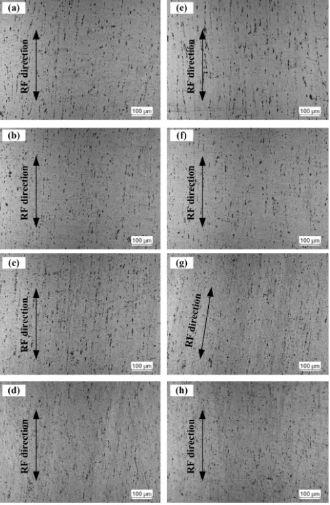
Figure 7 shows the microstructures of RF-deformed 6063
Al alloy bar with different ARRs from different parts. As shown in Fig. 7, with the increase of ARR, the microstruc-tures of both peripheral and central parts become denser along the RF direction. Therefore, the microstructures of starting material shown in Fig. 4 were further deformed and fragmented by the RF process. The higher the ARR, the more similar the microstructures of peripheral and central parts will become, indicating that the deformation degree of the RF-de-formed 6063 Al alloy bar is gradually homogeneous.
[image:4.595.55.283.69.239.2]3.3 Microstructure of RF-deformed 6063 Al alloy bar after SSIT
Figure 8 shows the microstructures of RF-deformed 6063 Al alloy bar with different ARRs from different parts after SSIT at 630 C for 10 min. As shown in Fig. 8, the grains of RF-deformed 6063 Al alloy bar after SSIT are finer and more spherical than those of starting material (Fig. 5). In Fig. 8(a) and (e), when the ARR is 30%, the grains of both the periph-eral and the central parts (marked with A and E, respectively) are large and irregular. In Fig. 8(b) and (f), when the ARR increases to 50%, the grains become finer and more spherical than those shown in Fig. 8 (a) and (e). However, some grains (marked with B and F) are still irregular. In Fig. 8(c), (d), (g)
Fig. 7 Microstructures of RF-deformed 6063 Al alloy bar with different ARRs from different parts: (a) 30%, (b) 50%, (c) 70% and (d) 85% from the peripheral part; (e) 30%, (f) 50%, (g) 70% and (h) 85% from the cen-tral part.
Fig. 8 Microstructures of RF-deformed 6063 Al alloy bar with different ARRs from different parts after SSIT at 630 C for 10 min: (a) 30%, (b) 50%, (c) 70% and (d) 85% from the peripheral part; (e) 30%, (f) 50%, (g) 70% and (h) 85% from the central part.
[image:4.595.307.548.69.438.2] [image:4.595.49.290.299.667.2]and (h), when the ARR increases to 70% and 85%, the micro-structures of both the peripheral and the central parts consist of fine and spheroidal grains, which is suitable for semi-solid forming.
Figure 9 illustrates the variations of the average grain size of different parts with the ARR after SSIT at 630 C for 10 min. As shown in Fig. 9, the average grain sizes of both the central and peripheral parts are reduced with the increase of ARR. The variation tendency experiences three different stages: precipitous reduction, gentle reduction and unobvious change, which is similar to the investigation reported by Lin
et al.,27) and Amir et al.24) Moreover, although the average
grain size of the central part is always smaller than that of the peripheral part, their differences (marked with H1, H2, H3 and H4) are decreased obviously as ARR increases from 30% to 85%.
To our knowledge, the microstructural evolution during RAP process can be divided into four stages: (1) deformation, (2) recovery and recrystallization, (3) liquid formation and grain fragmentation, (4) spheroidization and coarsening.28) Deformation plays a great role in the second stage, and the reason can be explained as follows: during the RF process, the deformation energy is accumulated and stored in the forms of vacancies, lattice defects and dislocations, providing the driving force for recovery and recrystallization.
During the SSIT process, when the RF-deformed samples are heated from the ambient temperature to 615 C (solidus temperature of 6063 Al alloy), recovery and recrystallization occur at the expense of the deformation energy. The critical size of steady recrystallization nucleus can be described by28)
R∗=2γ/∆E s
where R * is the critical size of steady recrystallization nucle-us; γ is the unit area interface energy; ΔES is the change of the unit volume fault energy and it increases with ARR. There-fore, the grain size (R *) reduces with the increase of ΔE
S. Then it can be concluded that there is an inverse relationship between the size of recrystallized grain and ARR.
When the samples are further heated to 630 C, liquid for-mation occurs firstly at the high angle grain boundaries of the recrystallized grains because these high angle grain
boundar-ies are in a high energy state. Meanwhile, the liquid pene-trates into the high angle grain boundaries when the energy is more than twice the solid/liquid interfacial energy, resulting in fragmentation of solid grains and decline of average grain size.
From the above analysis, the higher the ARR, the finer the recrystallized grain, which further induces the decline of av-erage grain size. The main cause for the precipitous reduction in average grain size may be that the RF process makes the deformation energy to be rapidly accumulated and abundant-ly stored in the RF-deformed 6063 Al alloy bar when the ARR increases from 30% to 50%. Hence the average grain sizes of both the peripheral and central parts are rapidly re-duced. When the ARR increases from 50% to 70%, it seems that the accumulating rate of deformation energy gradually falls, which weakens the effect of recrystallization on the evo-lution of grains. Therefore, the reduction tendency becomes gentle. The main cause for the unobvious change may be that the deformation degree of starting material reaches a peak value at 70% ARR and is hard to be further improved, possi-bly because that the vacancies, lattice defects, and disloca-tions are neutralized as the ARR reaches above 70%. There-fore, the deformation process of RF from 70% to 85% ARR plays a weak role in the reduction of the average grain size.
During the RF process, with the increase of ARR, the de-formation degree of the central part is gradually close to that of the peripheral part (Fig. 7). Therefore, although the aver-age grain size of the central part is always smaller than that of the peripheral part, the differences between the two are grad-ually decreased (Fig. 9). It can be concluded that the solid grains of semi-solid 6063 Al alloy bar are gradually homoge-neous with the increase of ARR.
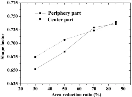
Figure 10 illustrates the variations of the shape factor of different parts with the ARR after SSIT at 630 C for 10 min. As shown in Fig. 10, the shape factors of both the peripheral and central parts are increased with the ARR. Namely, the spheroidization degrees are gradually improved. It has been discussed that higher ARR results in finer grain size. Besides, it was reported by Chen et al.19) that a smaller diffusion dis-tance caused by finer microstructure can increase the diffu-sion rate, which can promote the spheroidization of solid
[image:5.595.54.286.587.761.2]Fig. 9 Variations of the average grain size of different parts with the ARR after SSIT at 630 C for 10 min.
[image:5.595.312.542.592.761.2]grains in alloys. Therefore, the higher the ARR, the greater the diffusion rate, leading to a faster dynamics of spheroidiza-tion.
The results in Figs. 8–10 indicate clearly that the optimal process parameters for refining grains of 6063 Al alloy bar are 70% or 85% ARR at 630 C for 10 min, with which the aver-age grain size is less than 120 µm (Fig. 9) and the shape fac-tor is above 0.72 (Fig. 10). However, increasing ARR can drive up the production cost. Therefore, it can be concluded that 70% ARR at 630 C for 10 min is the optimal process parameter to refine grains of 6063 Al alloy bar for semi-solid forming.
4. Conclusion
(1) A modified RAP process including RF and subsequent SSIT was successfully introduced to refine the grains of 6063 Al alloy bar (φ120 mm × 800 mm) for semi-solid forming. And this method is very suitable for industrial applications.
(2) With the increase of area reduction ratio, the average grain sizes of both the peripheral and the central parts can be reduced and the spheroidization degrees can be improved. The variation tendency of grain size experiences three differ-ent stages: precipitous reduction, gdiffer-entle reduction and unob-vious change. And the solid grains of semi-solid 6063 Al al-loy bar are gradually homogeneous with the increase of ARR. Moreover, the optimal process parameter for refining grain is 70% ARR at 630 C for 10 min.
Acknowledgments
This work is supported by the National Natural Science Foundation of China for key Program (Grant No. 51335009), the Natural Science Foundation of Shaanxi Province of China (Grant No. 2014JQ7273) and the Xi an Science and Technol-ogy Plan Projects (Grant No. CXY1514 (1)).
REFERENCES
1) M.C. Flemings: Metall. Trans. A 22 (1991) 957–981.
2) N. Van Thuong, H. Zuhailawati, A.A. Seman, T.D. Huy and B.K. Dhindaw: J. Mater. Eng. Perform. 24 (2015) 2108–2116.
3) B.K. Kang, C.P. Hong, Y.S. Jang, B.H. Choi and I. Sohn: Mater. Trans.
57 (2016) 410–416.
4) C.P. Wang, Y.Y. Zhang, L.I. Di-Fan, H.S. Mei, W. Zhang and J. Liu: T. Nonferr. Metal. Soc. 23 (2013) 3621–3628.
5) F. Hosseini Yekta and SA. Sadough Vanini: P. I. Mech. Eng. B.-J. Eng
228 (2014) 1611–1620.
6) P.B. Li, T.J. Chen and Y. Ma: Mater. Trans. 57 (2016) 91–98.
7) R. Haghayeghi, E.J. Zoqui, A. Halvaee and M. Emamy: J. Mater. Pro-cess. Technol. 169 (2005) 382–387.
8) V. Dao, S. Zhao and W. Lin: Int. J. Appl. Electrom 41 (2013) 153–165.
9) P. Das, S. Dutta and S.K. Samanta: P. I. Mech. Eng. B.-J. Eng 227 (2013) 1474–1483.
10) S.C. Hogg, H.V. Atkinson and P. Kapranos: Metall. Mater. Trans., A 35 (2004) 899–910.
11) C.W. Lin, F.Y. Hung and T.S. Lui: Mater. Trans. 57 (2016) 135–142.
12) Y. Murakami, K. Miwa and M. Kito: Mater. Trans. 57 (2016) 168–173.
13) B. Binesh and M. Aghaie-Khafri: Mater. Charact. 106 (2015) 390–403.
14) D. Abolhasani, H.R. Ezatpour, S.A. Sajjadi and Q. Abolhasani: Mater. Des. 49 (2013) 784–790.
15) J.F. Jiang, Y. Wang and H.V. Atkinson: Mater. Charact. 90 (2014) 52– 61.
16) Y.B. Song, P. Kyung-Tae and C.P. Hong: Mater. Trans. 47 (2006) 1250– 1256.
17) J.F. Jiang, Y. Wang, J.J. Qu, Z.M. Du, Y. Sun and S.J. Luo: J. Alloy. Compd. 497 (2010) 62–67.
18) Z.D. Zhao, Q. Chen, Z.J. Tang and C.K. Hu: J. Alloy. Compd. 497 (2010) 402–411.
19) Q. Chen, Z.D. Zhao, Z.X. Zhao, C.K. Hu and D.Y. Shu: J. Alloy. Com-pd. 509 (2011) 7303–7315.
20) G.H. Yan, S.D. Zhao, S.Q. Ma and H.T. Shou: Mater. Charact. 69 (2012) 45–51.
21) J. Wang, D.H. Lu, H. Xiao, R.F. Zhou, R. Zhou and L.B. Wu: Solid State Phenom. 217–218 (2014) 418–425.
22) Q. Chen, Z.D. Zhao, G. Chen and B. Wang: J. Alloy. Compd. 632 (2015) 190–200.
23) Y.J. Wu, X.H. Dong and Q. Yu: Int. J. Mech. Sci. 93 (2015) 102–110.
24) A. Bolouri, M. Shahmiri and C.G. Kang: J. Alloy. Compd. 509 (2011) 402–408.
25) J.F. Jiang, Z.M. Du, Y. Wang and S.J. Luo: Solid State Phenom. 217–
218 (2014) 29–36.
26) H.V. Atkinson, K. Burke and G. Vaneetveld: Mater. Sci. Eng. A 490 (2008) 266–276.
27) H.Q. Lin, J.G. Wang, H.Y. Wang and Q.C. Jiang: J. Alloy. Compd. 431 (2007) 141–147.