http://www.scirp.org/journal/wjm ISSN Online: 2160-0503
ISSN Print: 2160-049X
Experimental Study of Clarification of Vortex
Structure by Changing Disk Acceleration Time
Hiroyuki Furukawa, Akihiro Wada, Takashi Watanabe
Department of Mechanical Engineering, Meijo University, Nagoya, Japan
Abstract
Disks with two different dimensions were used to clarify the differences in fi-nal vortex structures generated by the change in disk acceleration time. The experiment results and calculated results of vortex structures match when the disk thickness is 20 mm and the Reynolds number is 5000 - 15000. Also, they match when the disk thickness is 30 mm with a Reynolds number from 3000 - 5000 and 9000 - 20000. Even when the size of the disk and the Reynolds number are the same, the final vortex structures can be different due to dif-ferences in the disk acceleration time.
Keywords
Rotating Disk, Flow Instability, Bifurcation, EFD and CFD
1. Introduction
The flow brought about by a rotating object within a container is often seen in fluid machines which provide/get energy to fluids via the rotation of vaned wheels such as centrifugal pumps and turbines. Many related studies have been conducted by Bödewadt et al. [1]. If the gap between both disks is large, the flow has a separate boundary layer, as studied by Batchelor [2]. However, in many studies thus far, rotating disks have simply been used as something to provide peripheral velocity and the shape has not been taken into consideration much. However, it is known that the radial gap has a significant impact on the flow between the rotating disk and fixed disk on the base of the container [3]. The impact of this gap in the radial direction on the flow between the base of the container and the rotating disk is called as the edge effect [4].
Rotating flows can be found in fluid machinery and chemical reactors and they are examined to improve their performance [5]. When the flow around a How to cite this paper: Furukawa, H.,
Wada, A. and Watanabe, T. (2017) Expe-rimental Study of Clarification of Vortex Structure by Changing Disk Acceleration Time. World Journal of Mechanics, 7, 185- 194.
https://doi.org/10.4236/wjm.2017.78017
Received: June 30, 2017 Accepted: July 28, 2017 Published: July 31, 2017
Copyright © 2017 by authors and Scientific Research Publishing Inc. This work is licensed under the Creative Commons Attribution International License (CC BY 4.0).
http://creativecommons.org/licenses/by/4.0/ Open Access
rotating disk in a cylindrical casing represents a model of the flow in hard disk drives and stirrers, the radial clearance between the disk tip and the side wall of the casing is inevitable. Schouveiler et al. [6] implied that the radial clearance bores new spiral flows. Al-Shannag et al. [7] numerically examined the flow around corotating two disks connected by a central hub and showed the effect of the velocity fluctuation in the radial clearance on the interdisk flow. Hendriks [8] predicted a more realistic flow in a hard disk drive. He obtained Taylor vor-tices formed between the rotating disk and the side wall of the casing and found the jet-like radially outward flow on a rotating disk.
In research conducted thus far, rotating disks of different shapes are used to change the gap within cylindrical containers and experiments have been con-ducted in respect of the impact that the gap in the radial direction has on the disk rotor in the container and, as a result, from the difference in disk dimen-sions, fluid movement phases that changes with each disk have been confirmed. Hence, in this study, experiments have been conducted to clarify the edge effect using disks with different dimensions by focusing on the edge effect. The transi-tion scenario for the complex flow and the geometric effect changing the accele-ration time has not been well clarified. The purpose of this study is to clarify the vortex structure by changing disk acceleration time.
[image:2.595.229.521.514.703.2]2. Experiment Device and Its Procedure
2.1. Experiment Device
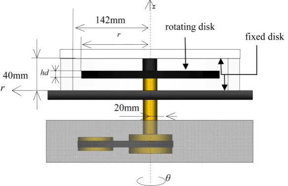
Figure 1 shows the main component of the experiment device. The cylindrical container containing the test fluid is constructed of two fixed disks at the top and the bottom and a cylindrical frame with an internal diameter of 142.0 mm and a thickness of 40.0 mm. The fixed disk and the cylindrical frame are both made of acrylic resin materials. The rotating disks are attached to the rotating axes and the axis diameter is 20.0 mm. So that the flow between the disks, which
Figure 1. The main part of the experimental device.
is the flow between the fixed disk and the rotating disk, is such that the space in the container with rotating disk is symmetrical, the disk joining part has the same diameter as the rotating axis of 20.0 mm. The material of the disk is dura-lumin and the whole thing is coated with matte black. The dimensions of the ro-tating disk fixed in the container are as follows. Disk: Radius r = 127.0 mm, thickness hd = 30.0 mm.
2.2. Surroundings of Experimental Device
The experiment devices used were an acrylic casing (Sanwa Kiki manufacturing) Xenon slit light source (500W, KS2000-30, Katou Mitsuken), an inverter (Mit-subishi Electrics), a control box (Sanwa Kiki manufacturing), a digital tachome-ter (Mitsubishi Electrics), and the main part of the experimental device, which was attached to them. Filming utilized a digital video camera (SONY HDR- CX560V) which has an effective pixel count of 6,140,000 (16:9) and, in this re-search, the filming was done with an average bit rate of 28 Mbps with a resolu-tion 1920 × 1080 pixels and framerate of 60 fps. The recorded image can be digi-tally processed via a computer. A slit light source was placed right next to the cy-lindrical container so that the irradiation position would be horizontal and the experiment device was placed in a dark room to avoid light from the outside. Moreover, to achieve the desired number of rotations, the motor rotation was controlled with an inverter and the setting of the disk acceleration time was conducted with a MELSOFT series GX Works II (Mitsubishi Electrics) and the number of rotations of the axis was confirmed using a digital tachometer.
The test fluid uses Newton liquid in which distilled water and glycerin are mixed together well at specified mass ratios. This research used the ratio 3:2 of water to glycerin in the test fluid. To obtain the kinetic viscosity ν, a specific gravity meter (Nihon Keiryoki Kogyo K. K) was used. Moreover, viscosity μ was measured used an SV type viscosity meter (SV-10 KK A & D).
The three-dimensional flow inside the container is visualized on a two-di- mensional plane using aluminum powder. The visualization using aluminum powder is done by mixing aluminum powder, which has been put into a sieve with a lattice width of 20 μm, with the test fluid. The amount of aluminum powder mixed in is 0.1 g for 2.5 l of test fluid. Moreover, to prevent aluminum powder from floating due to surface tension of the test fluid at this point, 1 - 2 droplets of household neutral detergent are mixed in.
2.3. Structure of Vortex Appearing in the Gap in the Radial
Direction
The Reynolds number 2
Re=
ω
rd v was used as an index of the flow. ω is the angular velocity of the rotating disk and is calculated from the number of disk rotations N. All rotating disks rotate counterclockwise. Rotating speed of the disk corresponding to the target Reynolds number is achieved from the initial stationary state by setting a disk accelerating time and matching that time. Thenafter achieving the rotation velocity target, then the final vortex structure is vi-sually confirmed after one minute 30 seconds.
On this occasion, two types of disks −20 mm and 30 mm—are used. Moreo-ver, disk acceleration times are 1 s and 30 s with a Reynolds number from 3000 - 20000 at 1000 intervals. It is thought that there are 4 types of vortex structures appearing in the gaps between the axes. The four types are polygonal, ring, posi-tive progressing spiral, and negaposi-tive progressing spiral.
2.4. Change in Acceleration Time
In past experiments, it was impossible to set the Reynolds number within a sti-pulated time. In this experiment, the disk acceleration time was changed using a control box and MELSOFT series GX Works II (Mitsubishi Electrics).
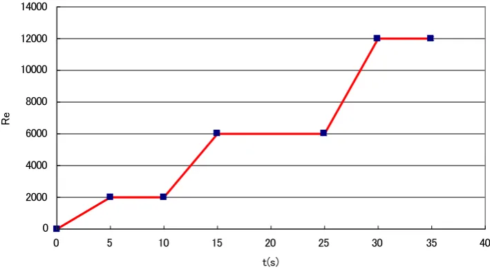
An example of the change in the disk acceleration time is shown in Figure 2. Between t = 0 s to t = 5 s, if angular velocity corresponding to a Reynolds num-ber of Re= 2000 is set to be reached in t = 5 s, the Reynolds number can be in-creased at a fixed angular acceleration. Moreover, in a similar way, the angular velocity is increased from t = 10 s to t = 15 s and between t = 25 s and t = 30 s. In this class, the change in the angular acceleration occurs only once from t = 0 s to
t = 1 s or t = 0 s to t = 30 s.
2.5. Parameters
Moreover, in the actual experiment, to obtain the desired Reynolds number Re, the required rotational velocity was derived from viscosity and specific gravity. The final rotational velocity of the disk is set in respect of this derived result.
The viscosity of the test fluid is taken to be μ(mPa·s), specific gravity s and the number of disk rotations, N(rpm). The representative velocity is taken to be
V(m/s), representative length r(m), and kinetic viscosity, ν(m2/s).
[image:4.595.180.535.508.703.2]The required number of rotations was derived from the following equation.
Figure 2. Example of programme of acceleration time.
0 2000 4000 6000 8000 10000 12000 14000
0 5 10 15 20 25 30 35 40
t(s)
R
e
(
)
( )
2 3 3
2
2
3 3
2
3
10 10
Re
10 10
10
r V r
r
s s
s
ω ω
µ µ
ν
− −
− −
−
× ×
× ×
= × = =
× ×
×
(1)
( )
2(
)
Re rad s
rs
µ
ω= × (2)
( )
2( )
2(
)
60 30
Re Re rpm
2π π
N
rs rs
µ µ
= × × = × (3)
3. Results
3.1. Numerical Results
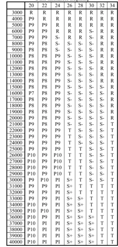
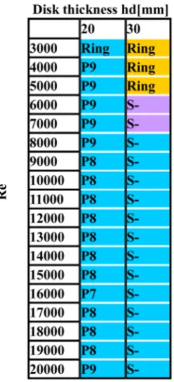
[image:5.595.284.477.303.707.2]The numerically calculated values for vortex structure when the disk accelera-tion time is 1 s are compared against the experimental results. Below, Figure 3
Figure 3. Numerical calculation results.
shows the numerically calculated results. This figure plots the Reynolds number on the vertical axis and the thickness of the disk on the horizontal axis. ts represents the disk acceleration time and h the thickness of the disk. Further-more, the polygonal vortex, ring vortex, and negatively progressing spiral vortex are abbreviated as P, R, and S-, respectively.
3.2. Structure of Vortex Appearing in the Gap in a Radial Direction
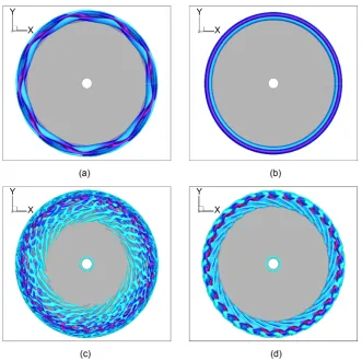
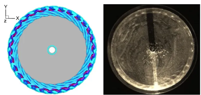
The structure of the vortex appearing in the radial gaps is shown below. Figure 4 shows an enlarged image of the tip of the radial gap of the container and the disk. The grey part is the disk. The vortex appearing on the disk side shows var-ious shapes depending on the Reynolds number, disk thickness, and disk accele-ration time.Disk vortex structures expected to appear are shown in Figure 5. These are results calculated, and show the types of vortex structures expected to appear in respect of each disk thickness hd and Reynolds number Re. The figure below shows the disk acceleration time as ts= 0 (s).
[image:6.595.209.541.363.693.2]Next, a ring vortex appears at a Reynolds number of 3000 when the disk thickness is 20 mm. A polygonal vortex appears at a Reynolds number of 4000 - 20000. A ring vortex appears at a Reynolds number of 3000 - 5000 when the disk
Figure 4. Structure of main vortices. (a) Polygonal vortex. (b) Ring vortex. (c) Positive travelling wave spiral vortex. (d) Negative travelling wave spiral vortex.
Figure 5. Results of numerical cal-culation for the final structure of the vortex.
thickness is 30 mm. A negatively progressing wave spiral vortex appears at a Reynolds number of 6000 - 20000. Furthermore, the vortex structures of poly-gonal vortex and negatively progressing spiral vortex are abbreviated as P and S-, respectively.
3.3. Experimental Results When the Disk Acceleration Times Are
Different
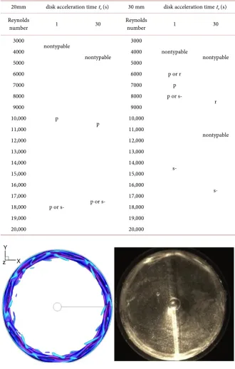
The vortex structures that appeared when the disk thickness was 20.0 mm and 30.0 mm with a disk acceleration time of 1 s and 30 s are shown in Table 1.
Different results were shown in the table when the disk thickness was 30 mm when the Reynolds number was 7000 - 10000. Furthermore, vortex structures which could not be clearly determined visually or as a polygon, ring, negatively progressing spiral—as p, r, s- were marked as undeterminable.
4. Comparison between Experimental and Numerical
Results
4.1. Vortex Structure
The vortex structure was filmed across the r-θ cross-section. Part of the still im-ages is shown from Figures 6-8.
Figure 6 shows that the final vortex structure seen when the disk thickness is 20.0 mm, the Reynolds number is 10,000, and the disk acceleration time is 1 s is a
Table 1. Comparison of experimental result when the disk acceleration time is 1 s with when 30 s.
20mm disk acceleration time ts (s) 30 mm disk acceleration time ts (s)
Reynolds
number 1 30 Reynolds number 1 30
3000
nontypable
nontypable
3000
nontypable
nontypable
4000 4000
5000
p
5000
6000 6000 p or r
7000
p
7000 p
r
8000 8000 p or s-
9000 9000
s-
10,000 10,000
11,000 11,000
nontypable
12,000 12,000
13,000 13,000
s-
14,000 14,000
15,000
p or s-
15,000 16,000
p or s-
16,000
17,000 17,000
18,000 18,000
19,000 19,000
[image:8.595.205.539.104.611.2]20,000 20,000
Figure 6. Polygonal vortex (hd= 20.0 mm,Re= 10,000, ts= 1 s).
polygonal vortex. Similarly, Figure 7 shows that the final vortex structure seen when the disk thickness is 30.0 mm, the Reynolds number is 15,000, and the disk acceleration time is 30 s is a negatively progressing spiral vortex. Figure 8 shows that the final vortex structure seen when the disk thickness is 30.0 mm, the Rey-nolds number is 10,000, and the disk acceleration time is 30 s is a ring vortex.
Figure 7. Spiral vortex of negative progressive wave (hd= 30.0 mm,Re= 15,000, ts= 30 s).
Figure 8. Ring vortex (hd= 30.0 mm,Re= 10,000, ts= 30 s).
4.2. Comparison of Reynolds Number
Results comparing the final vortex structures obtained by experiment and by numerical calculation results discretized using the difference method with the three-dimensional unsteady compressible Navier-Stokes equation are shown in Table 2. There was a comparison with the situation when the disk acceleration time is 1 s for all experiment conditions conducted on this occasion.
From the table, it can be said that the numerically calculated results and expe-riment results match when the disk thickness is 20 mm with a Reynolds number of 5000 - 1500 and when the disk thickness is 30 mm with a Reynolds number of 9000 - 20000.
5. Conclusions
Disks with two different dimensions were used to clarify the differences in final vortex structures generated by the change in disk acceleration time and the fol-lowing results were obtained based on visualization experiments and analysis results.
1) The experiment results and calculated results of vortex structures match when the disk thickness is 20 mm and the Reynolds number is 5000 - 15000. Al-so, they match when the disk thickness is 30 mm with a Reynolds number from
Table 2. Comparison of experimental result with calculated result.
Disk acceleration
time ts (S)
Disk thickness
hd (mm) Reynolds number
Experimental
result Calculated result
1
20 5000 - 15,000 p p
16000 - 20,000 s-
30
3000 - 5000 r r
6000 r or p
s-
7000 p
8000 p or s-
9000 - 20,000 s-
3000 - 5000 and 9000 - 20000.
2) Even when the size of the disk and the Reynolds number are the same, the final vortex structures can be different due to differences in the disk acceleration time.
Acknowledgements
This research was supported by the research grant from the Nitto Foundation. We appreciate good comments from reviewers.
References
[1] Bödewadt, U.T. (1940) Die Drehströmung über festem Grunde. Zeitschrift für An-gewandte Mathematik und Mechanik, 20, 241-253.
https://doi.org/10.1002/zamm.19400200502
[2] Batchelor, G.K. (1951) Note on a class of solutions of the Navier-Stokes equations representing steady rotationally symmetric flow. The Quarterly Journal of Mechan-ics and Applied MathematMechan-ics, 4, 29-41. https://doi.org/10.1093/qjmam/4.1.29 [3] Serre, E., Crespo Del Arco, E. and Bontoux, P. (2001) Annular and spiral patterns in
flows between rotating and stationary disk. Journal of Fluid Mechanics, 434, 65-68. https://doi.org/10.1017/S0022112001003494
[4] Tsutsui, M. (2004) Research Relating to Transition Pattern of Rotating Disk Flow in a Container. The Japan Society of Mechanical Engineers Fluid Engineering Lecture Series Thesis Collection, North Kyushu, 25-26 November 2004, CD523, 1-4. [5] Meeuwse, M., van der Schaaf, J. and Schouten, J.C. (2012) Multistage Rotor-Stator
Spinning Disc Reactor. AIChEJournal, 58, 247-255. https://doi.org/10.1002/aic.12586
[6] Schouveiler, L., Le Gal, P. and Chauve, M.P. (1998) Stability of a Traveling Roll Sys-tem in a Rotating Disk Flow. Physics of Fluids, 10, 2695-2697.
https://doi.org/10.1063/1.869793
[7] Al-Shannag, M., Herrero, J., Humphrrey, J.A.C. and Giralt, F. (2002) Effect of Radi-al Clearance on the Flow between Corotating Disks in Fixed CylindricRadi-al Enclosures. Transactions of ASME. Journal of Fluids Engineering, 124, 719-727.
https://doi.org/10.1115/1.1487355
[8] Hendriks, F. (2010) On Taylor Vortices and Ekman Layers in Flow-Induced Vibra-tion of Hard Disk Drives. MicrosystemTechnologies, 16, 93-101.
https://doi.org/10.1007/s00542-008-0765-2
Submit or recommend next manuscript to SCIRP and we will provide best service for you:
Accepting pre-submission inquiries through Email, Facebook, LinkedIn, Twitter, etc. A wide selection of journals (inclusive of 9 subjects, more than 200 journals)
Providing 24-hour high-quality service User-friendly online submission system Fair and swift peer-review system
Efficient typesetting and proofreading procedure
Display of the result of downloads and visits, as well as the number of cited articles Maximum dissemination of your research work
Submit your manuscript at: http://papersubmission.scirp.org/