Please cite this article as: M. Niaz Azari, M. Samami,S. M. Abedi Pahnehkolaei, Optimal Design of a Brushless DC Motor, by Cuckoo Optimization Algorithm, International Journal of Engineering (IJE), TRANSACTIONSB: Applications Vol. 30, No. 5, (May 2017) 668-677
International Journal of Engineering
J o u r n a l H o m e p a g e : w w w . i j e . i rOptimal Design of a Brushless DC Motor, by Cuckoo Optimization Algorithm
M. Niaz Azari*a, M. Samamib, S. M. Abedi Pahnehkolaeib
a Department of Electrical Engineering, University of Science and Technology of Mazandaran, Behshahr, Iran b Department of Electrical Engineering, Sari Branch, Islamic Azad University, Sari, Iran
P A P E R I N F O
Paper history:
Received 04 December 2016
Received in revised form 11 February 2017 Accepted 10 March 2017
Keywords: Brushless DC Motor Cuckoo Algorithm Objective Function Optimal Motor Design
A B S T R A C T
This contribution deals with an optimal design of a brushless DC motor, using optimization algorithms, based on collective intelligence. For this purpose, the case study motor is perfectly explained and its significant specifications are obtained as functions of the motor geometric parameters. In fact, the geometric parameters of the motor are considered as optimization variables. Then, the objective function has been defined. This function consists of three terms i.e. losses, construction cost and the volume of the motor which should be minimized simultaneously. Three algorithms i.e. cuckoo, genetic and particle swarm have been studied in this paper. It is noteworthy that, cuckoo optimization algorithm has been used for the first time for brushless DC motor design optimization. A comparative study between the mentioned optimization approaches shows that, cuckoo optimization algorithm has been converged to optimal response in less than 250 iterations and its standard deviation is 0.03 , while the convergence rate of the genetic and particle swarm algorithms are about 400 and 450 iterations with standard deviations of 0.07 and 0.06, respectively for the case study motor. The obtained results show the best performance for cuckoo optimization algorithm among all mentioned algorithms in brushless DC motor design optimization.
doi: 10.5829/idosi.ije.2017.30.05b.06
1. INTRODUCTION1
The use of DC motors has become common in industry, due to highlighted specifications such as vast speed control and high efficiency [1-3]. However, the presence of commutator and brushes can be considered as a major disadvantage of such motors due to constant erosion of the mentioned components which can finally lead to an increase in safety hazard and the maintenance cost. But this problem has been solved by the use of Brushless DC (BLDC) motors. In these motors electric circuits have been applied instead of commutator and brushes [2, 4].
So far, several investigations have been conducted on optimization of BLDC motor design. As stated in literature [5], a BLDC motor has been optimized by orthogonal multi-objective chemical reaction optimization algorithm (OMOCRO), in order to achieve
*Corresponding Author’s Email: [email protected] (Milad Niaz Azari)
maximum efficiency with minimal material cost. Consequently, a comparative experiment among non-dominated sorting genetic algorithm, multi-objective particle swarm and (OMOCRO) shows the best performance of (OMOCRO) for BLDC motor design optimization. Reference [6], has proposed a novel optimization method, search region management (SRM), in order to improve the efficiency of the local search algorithms. The mentioned method has been tested for optimal design of a BLDC motor with the help of FEA, in order to minimize the torque ripple. It has been stated in literature [7] a Multi-objective Krill Herd Algorithm (MOKH), using the beta distribution in the inertia weight tuning, has been proposed for electromagnetic optimization of a Brushless DC Motor with a promising performance.
Another investigation [8] has proposed the genetic algorithm for topology optimization of the stator teeth in a BLDC motor in order to reduce the torque ripple without decreasing the average torque. Son et al. [9] optimized BLDC motor through a population based algorithm called interstellar search method (ISM) with
mesh adaptive direct search. Reduction of the torque ripple has been considered as the main objective of this paper. Another study [10] deals with the optimal design of an interior permanent magnet BLDC motor, using cost effective ferrite magnets in order to maximize the flux density and minimize the torque ripple. The genetic algorithm has been applied for flared shape rotor structure optimization. Kim et al. [11] have optimized the anisotropic ferrite magnet shape and magnetization direction of an interiorPermanent Magnet BLDC Motor in order to maximize back-EMF ofthe mentioned motor with the help of (FEM). On the other hand, a 2-D analytical solution to predict the distribution of magnetic field and comparing the results with 2-D (FEM) in ironless BLDC motor, used in flywheel, has been raised by Liu et al. [12]. Investigation [13], discusses an outer rotor type motor design, used in the blower system of a vehicle in accordance to a BLDC and also BLAC motor with the help of finite element analysis.
In most of literatures mentioned that the influence of the required speed has been neglected in optimization and as a result, the motor power has not been well defined [5-10]. On the other hand, the applied optimization approaches are based on simple analysis with sensitivity to initial conditions which have been widely used in recent years. Therefore, employing a more up to date optimization algorithm seems to be vital. This investigation provides a detailed study in order to represent the essential equations for BLDC motor design, considering: Both speed and torque as mechanical required parameters and, using cuckoo optimization algorithm (COA) as a suitable approach for motor optimal design. To this end, the geometric parameters of the motor are considered as the optimization variables. Then the objective function is defined, based on minimization of losses, construction cost and the volume of the motor. Finally the obtained results of the three optimization approaches have been compared and the COA has been extracted as the best method.
2. MATERIALS OF A BLDC MOTOR AND THE APPLIED METHODS
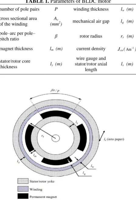
2. 1. BLDC Motor Structure Figure 1 depicts the structure of the studied motor in addition to its geometrical parameters [14]. Furthermore, the shown parameters, in Figure 1, have been introduced in Table 1.
2. 2. Design Features
2. 2. 1. Electromagnetic Torque For obtaining the total torque, the specifications which depend on the body material of the BLDC motor such as filling factor of the coil (kf), permanent magnet and the stator and
TABLE 1. Parameters of BLDC motor
number of pole pairs P winding thickness lw (m)
cross sectional area of the winding
Ac
(mm2) mechanical air gap lg (m)
pole–arc per pole–
pitch ratio β rotor radius rr (m)
magnet thickness lm (m) current density Jcu (Am2)
stator/rotor core
thickness ly (m)
wire gauge and stator/rotor axial
length
ls (m)
Figure 1. The structure of the studied BLDC motor
rotor core flux density (Br), should be given in the knee
point of the B-H curve.
Assuming the conductor and the magnetic field, are orthogonal to each other, the total torque can be obtained as follows [14, 15]:
w cu f c r
T A J k k lB (1)
(2 2 )
w w r g w
A l r l l (2)
where, l and kc represent the length of the conductor and the correction factor, respectively and Aw is the cross section of the coil.
Regardless of the armature reaction and also the reluctance of the stator and rotor core, the magnetic flux density will be as follows [14, 15]:
( ) ln
m r m
g
r g w
g
r g
r m
F B l
B
r l l
A
r l
r l
(3)
where, Fm, is the magneto-motive force and is the total reluctance of each winding. Ag can be obtained as:
( )
g s r g
A l r l
The electromagnetic torque of the BLDC motor based on its geometric parameters can be expressed in accordance to Equation (5).
1 (2 2 )
ln
f c r m s w r g w cu
em
r g w
r m
k k k k B l l l r l l J T
r l l r l
(5)
The leakage component of the magnetic field (k1) and also the active area of the auxiliary coil and magnet (k ) are expressed with the help of Equation (6) and
(7), respectively.
1 2
1 1
0.9[ / ( ( ))] 1
r g w
k
r p l l (6)
( , )
c
c
k k
k (7)
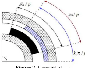
, indicates the span of the active coils, locating in the PM magnetic field, as shown in Figure 2. This parameter can be approximated by the following equation.
( , )[ (1 ) tanh(
min )]
kc ks ks kc (8)
It is noteworthy that, ks 1 and
is obtained by experience and testing.2. 2. 2. The Mechanical and Electrical Criteria For making a relation between the motor geometry and the desired velocity, the electrical and also mechanical criteria should be defined in order to restrict the rotational velocity. From the mechanical aspect, the bearings are able to withstand high rotational speeds.
Therefore, they hardly impose any limitation on rotational velocity. But on the other hand, other rotating parts, specially permanent magnet can impose limitations on the maximum rotational velocity. As a result, a non-magnetic rotating sleeve is applied in order to enhance the mechanical robustness of the rotor.
From electrical point of view, the electrical time constant ( L R/ ), can limit the maximum rotational velocity.
Figure 2. Concept of
R and L represent the resistance and the inductance of each winding, respectively.
2. 2. 3. Cost of Materials The volume of the applied materials which depend on the motor geometry have significant impacts on the motor cost as expressed in Equation (9).
m w y
C C C C (9)
where, Cm, Cw and Cyrepresent the costs of permanent magnet, winding and stator/rotor core, respectively. Each term of Equation (9), can be written in detail as follows.
1 2
m m m m m
C c V c p (10)
w w g f w w
C c A k V (11)
y y y t
C c V (12)
where, cm1, cw and cy are the costs per unit mass of permanent magnet, winding and core materials, respectively.m,wandyrepresent the mass densities of permanent magnet, winding and rotor/stator core, respectively. Finally, Vm, Vw and Vt are the volumes of the permanent magnet, winding and rotor/stator core, respectively.
2. 2. 4. Losses in BLDC Motors Losses in BLDC motors are divided into three categories i.e. electrical, magnetic and mechanical losses. The power loss due to resistance of windings can be obtained as follows.
2
cu f c et w s cu
P k k k A l J (13)
On the other hand, the eddy currents and hysteresis losses are considered as two major magnetic losses of a BLDC motor.
Assuming equal magnetic flux of the air-gap and the core, the maximum magnetic density of the stator is expressed as [14]
1
2 ln
r m sy
r g w
y
r m
k B l B
r l l pl
r l
(14)
Thus, the following equations are obtained for eddy current and hysteresis losses, respectively.
2 2
e e y sy sy
P k V B f (15)
n
h h y sy sy
P k V B f (16)
where, y is the density of the motor material and Vsy
frequency in Equations (15) and (16) is calculated in accordance to Equation (17).
/ 2
r
f pw (17)
On the other side, the mechanical losses in a BLDC motor can be divided into two categories including; friction and windage. The friction losses can be written as follows [14].
2
b
b f b i r
N
P F d (18)
where, Fb and di are the load and the internal radius of the bearing. On the other hand, f and Nb represent the bearing friction factor and the number of bearings respectively. The windage losses can be obtained as follows.
3 4
w r f air r r s
P k C r l (19)
where, kr and air represent the roughness factor of the rotor and the air density respectively and Cf is the friction factor which is obtained by Equation (20) in which Re is the Couette-Reynolds number.
0.3
4 0.5
0.3
4 0.2
/
0.5150 500 Re 10
Re /
0.0325 10 Re
Re
g r
f
g r
l r
for C
l r
for
(20)
Reairw r lr r g/air
1 (2 2 )
ln
f c r m s w r g w cu e h
em
r g w r
r m
k k k k B l l l r l l J P P T
r l l w
r l
(21)
( ) /
out em w b r
T T P P (22)
In accordance to the obtained magnetic and mechanical losses, the modified formula of the electromagnetic and also the output torque can be modified as Equations (21) and (22). Also, the total losses of a BLDC motor can be expressed as:
total cu h e b w
P P P P P P (23)
3. OPTIMIZATION METHODS
These paper apply three different evolutionary algorithms i.e. Cuckoo (COA) [16], genetic (GA) [17, 18] and particle swarm (PSO) [19-21], for optimal design of the BLDC motor. GA is a popular and applied algorithm because of several reasons such as, its high intuitiveness, ease of implementation, its high capability to solve highly nonlinear mixed integer optimization
problems, large number of parameters and obtaining multiple local optima. On the other hand, PSO, has the same advantages as GA, but with better computational efficiency by applying statistical analysis and formal hypothesis testing. But this study has applied the COA for optimal design of BLDC motor for the first time. The cuckoo optimization algorithm has superiority to many other optimization algorithms i.e. GA and PSO, typically for multi-objective functions. In COA, the local search is performed with higher efficiency because there is only a single parameter apart from the population. In fact the only parameter which should be adjusted is the fraction of the nests needed to be abandoned (Pa). This issue improves the computing
power and speed. GA and PSO are common algorithms and have been completely described in references [17-21]. But since, COA, has been used as the main algorithm for motor optimal design in this study, an initial understanding from the concept of these algorithms is presented as follows.
3. 1. Cuckoo Optimization Algorithm Cuckoo Optimization Algorithm (COA) has been inspired by the life of a bird, called cuckoo [16]. The initial population of COA which forms various societies, consists of cuckoos and eggs. Each cuckoo has some eggs and also an Egg Laying Radius (ELR). The cuckoos lay eggs inside their equivalent ELR and in the nests of other host birds. Among all the eggs, those ones, which are similar to the eggs of the host birds can grow up. The rate of grown eggs indicates the suitability of the area. The area with more remained eggs has higher profit. Cuckoos always search for areas with highest profit for egg laying. Therefore, selecting the best place is an important term which should be optimized by the cuckoos. The cuckoos which live in the worst habitats always are removed. Each cuckoo travels a specific percent of the whole path toward the ideal habitat with a clarified deviation which are known as
and respectively. These two parameters help the cuckoos to find the ideal habitat. The maximum number of cuckoos should be confined in the specific environment. In fact, cuckoos have been clustered and the best habitat is detected to achieve the objective point. Consequently, the new cuckoo population can travel to the objective habitat. Now, the survival of eggs in the nest are checked and the profit value is obtained. A suitable profit value can lead to stopping the process. Otherwise, the whole process should start from the beginning in accordance to the flowchart, presented by Amiri and Mahmoudi [16]. In fact, the survival process of cuckoos should finally converge to a condition with only one cuckoo society, containing the same profit values.literatures [16-21], the determinave parameters of the optimization algorithms are introuduced. This parameters are
and for COA; the cross over rate and also the percentage of mutation for GA and (C1 &2
C ) for PSO. (C1 & C2) determine the traveled distance of a particle in each iteration [19-21]. The amount of the aforementioned parameters of the optimization algorithms, are measured in 20 different conditions. Each measurement is implemented individually for about 50 times and finally, The effective parameters, mentioned in Table 2, are obtained from the eights, twentieth and fourth implementation of COA, GA and PSO respectively.
4. OPTIMIZATION PROBLEM DATA
4. 1. Design Variables and Constant Values The optimization variables are those parameters of the case study motor that should be optimized. These parameters are presented in the following vector.
]
[
m y w g s r u T
c c
p l l l l l r J A
x (24)
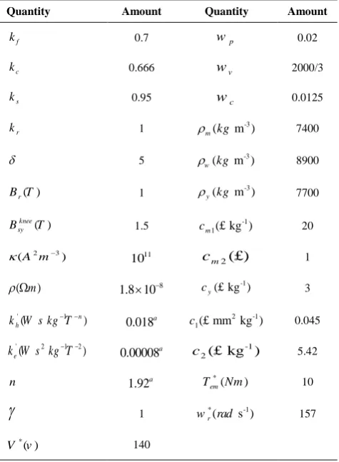
Generally, there are 10 different design variables that should be optimized. Other quantities i.e. power losses, output torque, costs and volume of the motor can be calculated through them. The aforementioned design variables were defined in Table 1. while, the constant parameters of this motor is presented in Table 4. In addition to these parameters, other adjustable coefficients of the COA are also presented in Table 3. 4. 2. Objective Function, with Considering the Constraints An appropriate definition of the objective function with consideration of the constraints is always known as the most significant issue in solving any optimization problem. The main concern in this investigation includes reduction of costs, volume and power loss of a BLDC motor. For this reason, the objective function will be as follows:
TABLE 2. The value of effective optimization parameters
COA GA PSO
Cross over rate Mutation (%)1
C C2
0.05 30 0.8 0.1 1.6 2
TABLE 3. Other COA coefficients
Number of Cuckoos 40 Max number of Cuckoos 200
Min number of eggs 2 30
Max number Of eggs 5 0.05
Number of clusters 2 Max iteration 500
TABLE 4. Constant parameters of the BLDC motor Amount Quantity
Amount Quantity
0.02 p
w
0.7
f
k
2000/3 v
w 0.666
c
k
0.0125 c
w 0.95
s
k
7400 -3
( m )
m kg
1
r
k
8900 -3
( m )
w kg
5
7700 -3
( m )
y kg
1 ( )
r
B T
20 -1
1( kg )£
m c
1.5 ( )
knee sy
B T
1
2(£)
m c 11
10
2 3
(A m )
3 -1
( kg )£
y
c
8 1.8 10 ( m)
0.045 2 -1
1( mm kg£ )
c
0.018a
' 1
( n)
h
k W s kg T
5.42
-1 2( kg )£
c
0.00008a
' 2 1 2
( ) e
k W s kg T
10 *
( )
em
T Nm
1.92a
n
157
* -1
( s )
r
w rad
1
140 *
( ) V v
a
For M19 lamination with a thickness of 0.35mm
0( ) V t( ) P total( ) C ( )
f x w V x w P x w C x (25)
where, C x( ), Ptotal( )x and Vt( )x represent, cost function, power loss function and volume function of the motor, respectively. On the other hand, wC, wP and
V
w are the related weight of cost function, power loss function and volume function of the motor. In fact, these coefficients clarify the impact of each function.
In addition to electrical and mechanical constraints, some other limitations such as thermal, cost and manufacturing constraints are of great importance. The only electrical constraint is the voltage which can be obtained with appropriate selection of the winding diameter. Similarly, the mechanical constraints can be expressed as follows.
* *
em em
max
r r
T T
(26)
where, *
em
T and *
r are arbitrary torque and speed
respectively. max
r is considered as the maximum speed
minimum air-gap ( m in g
l ) and the minimum area of the section ( min
c
A ).
Other constraints, caused by thermal limitations and saturation effect, are expressed as follows.
2
knee
sy sy
f w cu
B B
k l j k (27)
where, knee sy
B represents, the magnetic flux density at the knee point of the B-H curve and k is the maximum permissible temperature of the windings.
After considering the impact of the electromagnetic torque, speed and magnetic flux density constraints, the objective function has been modified as follows.
0
max
* *
( ) ( ) ( ) ( )
1
(1 ) (1 ) ( 1)
V t P total C
sy
em r
knee
u u u
em r sy
f x w V x w P x w C x
B
T w
f f f
T w B
(28)
1 ( )
1
u x
f x
e
where,
is a tiny amount and is considered as a constant large number.4. 3. Summary and Discussion For implementation of the BLDC motor optimization problem, the significant specifications of the motor are obtained as functions of the motor geometric parameters. The geometric parameters are mentioned in Table.1. In fact the mentioned parameters of the motor are considered as optimization variables and other quantities i.e. power losses, output torque, costs and volume of the motor can be calculated and optimized through them. The objective function consists of three terms including, losses, motor volume and manufacturing cost. The cost term is calculated by Equation (9), this Equation can be written in detail in accordance to Equations (10)-(12).
Equations (3) and (4) are needed to define Equation (11). The total losses of a BLDC motor can be expressed as Equation (23). This equation has 5 terms including, Equations (13), (15), (16), (18) and (19). Equation (14) is essential for defining Equations (15) and (16) and also Equation (20) is necessary for defining Equation (19). For clarifying the impact of each function the related weight of cost function, power loss function and volume function of the motor is considered as in Equations (25). Equations (26) and (27) express the constraints of the objective function. By considering the constraints in Equation (25), the final objective function is shown as Equation (28). By means of optimization algorithms which are implemented on Equation (28), the geometric parameters and also the volume of the motor will be optimal in addition to losses and manufacturing cost simultaneously.
5. SIMULATION RESULTS AND DISCUSSION
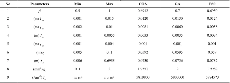
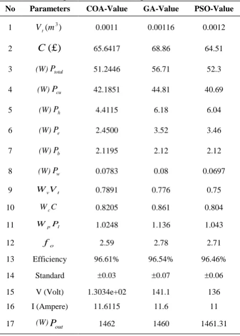
5. 1. Technical Analysis of the Optimized Parameters After implementation of the algorithms according to the effective parameters, mentioned in subsection 3.2; design variables and constant values, mentioned in subsection 4.1 and also the modified objective function, presented in subsection 4.2, the optimal parameters of the case study motor are obtained. These values along with the minimum and maximum values of the parameters are given in Table 5. It should be noted that, GA and PSO results are validated with reference [14]. According to Table 5, when COA is applied, most of the geometrical optimized parameters i.e., lm , lw ,lg and ls have the lowest values. Therefore, the motor has the lowest possible volume and lowest cost. On the other hand, the cross sectional area of the winding and the current density (Ac and Jcu) are also more applicable.
TABLE 5. The limitations and optimal value of the motor
PS0 GA
COA Max
Min Parameters
No
0.6950 0.7
0.6912 1
0.5
β
1
0.0124 0.0130
0.0120 0.015
0.001
m
l (m) 2
0.0058 0.0060
0.0081 0.01
0.002 y
l
(m) 3
0.0034 0.0035
0.0033 0.0055
0.001
w
l (m) 4
0.001 0.001
0.001 0.004
0.001 g
l (m) 5
0.059 0.0595
0.0592 0. 1
0.005
r
r (m) 6
0.0732 0.0756
0.0730 0.6933
0.006
s
l (m) 7
1.9982 2
1.9551 2
0. 1
c
A (mm2) 8
5784573 5800000
5819800 6
610
6
310 cu
As a result, the objective function has the best value, using COA, as presented in Table 6. Another significant issue in any optimization approach is the convergence rate of the algorithm. The COA, converged after 250 iteration while the GA and PSO converge after 400 and 450 iterations, respectively. This issue indicates the suitable convergence rate of COA.
5. 2. The Impact of Motor Geometrical Parameters on the Objective Function Figure 3 shows the variation of the objective function, due to changing each geometrical parameter of the motor, while the rest of parameters remain constant. This figure is divided into 9 subfigures and is labeled from (a) to (i). Each subfigure depicts the impact of changing each geometrical parameter of the motor i.e. P, , lm ,ly ,
w
l , rr, ls,lg and Jcu, on the objective function, respectively.
In all the subfigures, the red line, blue line and green point represent the proposed objective function variation, unconstrained objective function and the optimal point, respectively.
TABLE 6. Specifications of the optimized BLDC motor PSO-Value GA-Value
COA-Value Parameters
No
0.0012 0.00116
0.0011 3
( )
t V m
1
64.51 68.86
65.6417
( )£ C
2
52.3 56.71
51.2446
total
P (W) 3
40.69 44.81
42.1851
cu
P (W) 4
6.04 6.18
4.4115
h
P (W) 5
3.46 3.52
2.4500
e
P (W) 6
2.12 2.12
2.1195
b
P (W) 7
0.0697 0.08
0.0783
w
P (W) 8
0.75 0.776
0.7891
v t
W V 9
0.804 0.861
0.8205
c
W C 10
1.043 1.136
1.0248 p l
W P
11
2.71 2.78
2.59
o f
12
96.46% 96.54%
96.61% Efficiency
13
0.06 0.07
0.03
Standard 14
136 141.1
1.3034e+02 V (Volt)
15
11 11.6
11.6115 I (Ampere)
16
1461.31 1460
1462 out
P (W) 17
In accordance to Figure 3a, the large number of poles causes an increment in the motor manufacturing cost and also a decrement in the magnetic losses due to low density of magnetic flux in stator and rotor core. It should be noted that, this issue has no impact on the volume of the motor. By considering the proposed objective function and Figure 3a, it is concluded that, applying higher number of poles can lead to a better design of the motor. However, this issue causes an increment in the leakage magnetic flux and a decrement in the output torque. According to Figure 3b, the value of
has no effect on the volume of the motor. But it is noteworthy that, a lower value of
can lead to a reduction in the cost, magnetic leakage flux, magnetic losses and also the output torque. On the other hand, a large value of
can lead to a decrement in the output torque due to its effect on increasing the magnetic leakage flux.Figure 3c shows that, reduction of lm leads to improvement of manufacturing cost, volume and losses of the BLDC motor. But on the other hand, the output torque and the maximum speed of the motor still keep decreasing as before. As shown in Figure 3d, an increment in ly will lead to a reduction in the magnetic losses and causes an increment in the cost and volume of the motor. It should be noted that, considering a very small value forly , may lead to saturation. Figure 3e, shows that, the existence of high space for winding has different impacts on the cost and volume of the motor. But in general, it can lead to improvement of the efficiency. It is noteworthy that, lw should not be lower than a permissible amount.
Otherwise, the motor will not be able to produce a suitable torque. The radius of the rotor (rr ) is considered as one of the most significant parameters in a BLDC motor design. As shown in Figure 3f, by reducing the rr value, all the three items in the objective function will be reduced simultaneously. But it should be noted that, a very small rr value has negative effect on producing the necessary output torque and on the other hand, a very large rr value has inverse effect on the maximum speed of the motor. Figure 3g depicts that, a small value of ls is favorable, but unfortunately, this small amount can lead to an adverse impact on the output torque of the motor.
This issue is not desirable. As shown in Figure 3h,
g
l which shows the air-gap amount, is considered to have its minimum value.
Figure 3. Objective function variation, due to changing each geometrical parameter of the BLDC motor
Although, increasing the current density can lead to an improvement in the cost and volume of the motor, but it is noteworthy that, the impact of an increment in the copper losses is able to overcome the two aforementioned advantages.
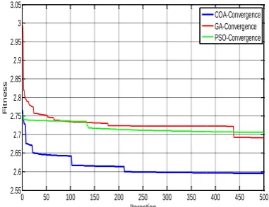
5. 3. The Comparison of COA Performance with GA and PSO Figure 4 and Table 7 show the convergence rate, fitness and also the standard deviation of COA, GA and PSO algorithms.
Figure 4.
The convergence waveform comparison of COA,
GA and PSO
TABLE 7. The comparison of applied methods Convergence rate Standard deviation
Fitness Algorithm
250
0.03
2.59 COA
400
0.07
2.78 GA
450
0.06
2.71 PSO
By considering, Table 7 and Figure 4, it is concluded that, COA algorithm has the best performance among all the described algorithms for optimal design of a BLDC motor.
6. CONCLUSION
In this paper, an optimal design of a BLDC motor, using three optimization approaches i.e. COA, GA and PSO has been studied. The priorities of parameters optimization in design of a motor are different in various applications. Therefore, the importance of this problem has become more obvious due to simultaneous parameter optimization. This investigation firstly clarifies significant specifications of the motor as functions of the motor geometric parameters. Then, the objective function has been defined in order to minimize the losses, construction cost and the volume of the motor simultaneously. Three different optimization
1 2 3 4 5 6
0 5 10 15
P a
0.5 0.6 0.7 0.8 0.9 1 0
5 10 15
Beta b
0 5 10 15
0 5 10 15
Lm c
2 4 6 8 10
0 5 10 15
Ly
O
b
je
c
ti
v
e
v
a
lu
e
d
1 2 3 4 5 6
0 5 10 15
Lw e
20 40 60 80 100 0
5 10 15 20
Rr
f
0 2 4 6 8
0 5 10 15 20
Ls g
0 2 4 6 8
2 4 6 8
Lg h
3 3.5 4 4.5 5 5.5 6 2
4 6 8
Jcu i
Unconstrained Constrained Optimal
0 50 100 150 200 250 300 350 400 450 500 2.55
2.6 2.65 2.7 2.75 2.8 2.85 2.9 2.95 3 3.05
Iteraation
F
it
n
e
ss
approaches i.e. COA, GA and PSO have been applied for the case study motor optimal design. It is noteworthy that, COA has been used for the first time for this purpose. The obtained results of three optimization methods have been compared together and finally it is concluded that, COA can converge to an optimal response in less than 250 iterations, while this value is 400 and 450 iterations for GA and PSO, respectively. As a result, the proposed method has an acceptable convergence rate. On the other hand, the obtained fitness value and the standard deviation of COA is more applicable, compared with GA and PSO.
7. REFERENCES
1. Pyrhonen, J., Jokinen, T. and Hrabovcova, V., "Design of rotating electrical machines, John Wiley & Sons, (2009). 2. Tian, W., "Design of permanent magnet brushless DC motor
control system based on dspic30f4012", Procedia Engineering, Vol. 29, (2012), 4223-4227.
3. Afjei, E., Hashemipour, O., Saati, M. and Nezamabadi, M., "A new hybrid brushless DC motor/generator without permanent magnet", International Journal of Engineering Transactions B Applications, Vol. 20, No. 1, (2007), 77-86.
4. Zolfaghari, M. and Taher, S., "Fuzzy approximation model-based robust controller design for speed control of bldc motor",
International Journal of Engineering-Transactions C: Aspects, Vol. 28, No. 3, (2014), 426-432.
5. Duan, H. and Gan, L., "Orthogonal multiobjective chemical reaction optimization approach for the brushless DC motor design", IEEE Transactions on Magnetics, Vol. 51, No. 1, (2015), 1-7.
6. Lee, T.-Y., Trung, P. X., Kim, J.-W., Kim, Y.-J. and Jung, S.-Y., "Search region management method for local search algorithm employing design optimization of brushless dc motor", IEEE Transactions on Magnetics, Vol. 52, No. 3, (2016), 1-6. 7. Ayala, H. V., Segundo, E. H., Mariani, V. C. and Coelho, L. d.
S., "Multiobjective krill herd algorithm for electromagnetic optimization", IEEE Transactions on Magnetics, Vol. 52, No. 3, (2016), 1-4.
8. Ishikawa, T., Yonetake, K. and Kurita, N., "An optimal material distribution design of brushless DC motor by genetic algorithm considering a cluster of material", IEEE Transactions on Magnetics, Vol. 47, No. 5, (2011), 1310-1313.
9. Son, B., Park, G.-J., Kim, J.-W., Kim, Y.-J. and Jung, S.-Y., "Interstellar search method with mesh adaptive direct search for optimal design of brushless DC motor", IEEE Transactions on Magnetics, Vol. 52, No. 3, (2016), 1-4.
10. Yoon, K.-Y. and Kwon, B.-I., "Optimal design of a new interior permanent magnet motor using a flared-shape arrangement of ferrite magnets", IEEE Transactions on Magnetics, Vol. 52, No. 7, (2016), 1-4.
11. Kim, H.-s., You, Y.-M. and Kwon, B.-I., "Rotor shape optimization of interior permanent magnet BLDC motor according to magnetization direction", IEEE Transactions on Magnetics, Vol. 49, No. 5, (2013), 2193-2196.
12. Liu, X., Hu, H., Zhao, J., Belahcen, A., Tang, L. and Yang, L., "Analytical solution of the magnetic field and emf calculation in ironless BLDC motor", IEEE Transactions on Magnetics, Vol. 52, No. 2, (2016), 1-10.
13. Lee, T.-Y., Seo, M.-K., Kim, Y.-J. and Jung, S.-Y., "Motor design and characteristics comparison of outer-rotor-type BLDC motor and blac motor based on numerical analysis", IEEE Transactions on Applied Superconductivity, Vol. 26, No. 4, (2016), 1-6.
14. Rahideh, A., Korakianitis, T., Ruiz, P., Keeble, T. and Rothman, M., "Optimal brushless DC motor design using genetic algorithms", Journal of Magnetism and Magnetic Materials, Vol. 322, No. 22, (2010), 3680-3687.
15. Lai, S. H., "Design optimisation of a slotless brushless permanent magnet DC motor with helically-wound laminations for underwater rim-driven thrusters", University of Southampton, (2006),
16. Amiri, E. and Mahmoudi, S., "Efficient protocol for data clustering by fuzzy cuckoo optimization algorithm", Applied Soft Computing, Vol. 41, (2016), 15-21.
17. Arashloo, R. S., Martinez, J. L. R., Salehifar, M. and Moreno-Eguilaz, M., "Genetic algorithm-based output power optimisation of fault tolerant five-phase brushless direct current drives applicable for electrical and hybrid electrical vehicles",
IET Electric Power Applications, Vol. 8, No. 7, (2014), 267-277.
18. Yousefi, A., Rahmani, A., Farzanegan, A. and Rostami, S., "Simulation and genetic algorithms for optimizing comminution circuit at gol-e-gohar iron plant (research note)", International Journal of Engineering-Transactions C: Aspects, Vol. 26, No. 6, (2013), 663-670.
19. Kazerooni, K., Rahideh, A. and Aghaei, J., "Experimental optimal design of slotless brushless pm machines based on 2-D analytical model", IEEE Transactions on Magnetics, Vol. 52, No. 5, (2016), 1-16.
20. Nahvi, H. and Mohagheghian, I., "A particle swarm optimization algorithm for mixed variable nonlinear problems", International Journal of Engineering, Vol. 24, No. 1, (2011), 65-78. 21. Akbarpour, H., Karimi, G. and Sadeghzadeh, A., "Discrete multi
Optimal Design of a Brushless DC Motor, by Cuckoo Optimization
Algorithm
RESEARCH NOTE
M. Niaz Azaria, M. Samamib, S. M. Abedi Pahnehkolaeib
a Department of Electrical Engineering, University of Science and Technology of Mazandaran, Behshahr, Iran b Department of Electrical Engineering, Sari Branch, Islamic Azad University, Sari, Iran
P A P E R I N F O
Paper history:
Received 04 December 2016
Received in revised form 11 February 2017 Accepted 10 March 2017
Keywords: Brushless DC Motor Cuckoo Algorithm Objective Function Optimal Motor Design
ديكچ ه
متیروگلا زا هدافتسا اب میقتسم نایرج کبوراج نودب روتوم کی زا هنیهب یحارط یسررب هب هلاقم نیا هنیهب یاه
رب هک یزاس
یم دنتسه یعمج شوه هیاپ هصخشم و هدش هداد حیضوت ًلاماک هعلاطم دروم روتوم ادتبا ،روظنم نیا یارب .دزادرپ
مهم یاه
زا یعباوت لکش هب نآ ناونع هب روتوم یسدنه یاهرتماراپ ،تقیقح رد .تسا هدش هدروآ تسد هب روتوم یسدنه یاهرتماراپ
هنیهب یاهریغتم هدش هتفرگ رظن رد یزاس
یم شخب هس زا لکشتم عبات نیا .تسا هتشگ فیرعت فده عبات سپس .دنا هک دشاب
یم روتوم مجح و تخاس هنیزه ،تافلت لماش یم هک دندرگ
لکش هب تسیاب مه
هس هلاقم نیا رد .دندرگ ممینیم نامز
هنیهب متیروگلا متیروگلا لماش یزاس
هتفرگ رارق هعلاطم دروم تارذ عامتجا و کیتنژ ،هتخاف یاه ،هک تسا رکذ نایاش .دنا
هنیهب یارب راب نیلوا یارب هتخاف متیروگلا لاطم کی .تسا هتفرگ رارق هدافتسا دروم کبوراج نودب روتوم یحارط یزاس
هع
هسیاقم متیروگلا نیب ام یا یم ناشن هدش دای یاه
زا رتمک رد هتخاف متیروگلا ،هک دهد 250
یدرادناتسا فارحنا اب و رارکت
لداعم 0.03
یم ییارگمه هب بیترت هب تارذ عامتجا و کیتنژ متیروگلا ییارگمه خرن هکیلاح رد .دسر
400 و 450 اب
فارحنا لداعم یدرادناتسا 0.07
و 0.06
یم ناشن هدمآ تسد هب جیاتن .دشاب نیبام هتخاف متیروگلا درکلمع نیرتهب هدنهد
متیروگلا هنیهب روظنم هب هدش دای یاه یحارط یزاس
یم میقتسم نایرج کبوراج نودب روتوم .دشاب