http: // www.ijrtsm.com© International Journal of Recent Technology Science & Management 55
ISSN : 2455-9679
[Preeti et al. , 4(3), Mar 2019] Impact Factor : 2.865
IJRTSM
INTERNATIONAL JOURNAL OF RECENT TECHNOLOGY SCIENCE & MANAGEMENT
“DESIGN & ANALYSIS OF SPUR GEAR USING DIFFERENT MATERIAL BY ANSYS
SOFTWARE”
Preeti Gajbhiye
1,
Prof. Ranjeet Kumar
2, Dr. R.S. Shikarwar
3 1M.Tech. Scholar, Dept. of Mechanical Engineering, Vaishnavi Institute of Technology & Science Bhopal, Mp, India 2 Assistant Professor, Dept. of Mechanical Engineering, Vaishnavi Institute of Technology & Science Bhopal, Mp,
India
3Professor, Dept. of Mechanical Engineering, Vaishnavi Institute of Technology & Science Bhopal, Mp, India
ABSTRACT
In the gear design the bending stress and surface strength of the gear tooth are considered to be one of the main contributors for the failure of the gear in a gear set.In this paper contact stresses are calculated by using analytical method as well as Finite element analysis. To estimate bending stress modified Lewis beam strength method is used. CATIA solid modeling software is used to generate the 3-D solid model of spur gear. ANSYS workbench software package is used to analyze the bending stress. Contact stresses are calculated by using modified AGMA contact stress method. In this also CATIA modeling software is used to generate contact gear tooth model. ANSYS 19.2 software package is used to analyze the contact stress. Finally these two methods contact stress results are compared with each other.
Keyword: CATIA,ANSYS, Contact stress, Gear, Spur gear, FE method
I.
I
NTRODUCTIONGears are used for a wide range of industrial applications. They have varied application starting from textile looms to aviation industries. They are the most common means of transmitting power. They change the rate of rotation of machinery shaft and also the axis of rotation. For high speed machinery, such as an automobile transmission, they are the optimal medium for low energy loss and high accuracy. Their function is to convert input provided by prime mover into an output with lower speed and corresponding higher torque. Toothed gears are used to transmit the power with high velocity ratio. During this phase, they encounter high stress at the point of contact. A pair of teeth in action is generally subjected to two types of cyclic stresses:
i. Bending stresses inducing bending fatigue ii. Contact stress causing contact fatigue.
1.1 SPUR GEAR
Spur gears are the most common type of gears. They are used to transmit rotary motion between parallel shafts i.e., they are usually cylindrical in shape, and the teeth are straight and parallel to the axis of rotation. Sometimes many spur gears are used at once to create very large gear reductions. Spur gears are used in many devices but not
http: // www.ijrtsm.com© International Journal of Recent Technology Science & Management 56
ISSN : 2455-9679
[Preeti et al. , 4(3), Mar 2019] Impact Factor : 2.865
II.
PROBLEM
DEFINITION
One of the main causes for failure of the gear tooth is bending stresses near the root of the gear and the contact stresses where the gears meet. The main objective of this paper is to analyze the bending stresses in the spur gear. When the spur gears mesh a tangential and a radial load acts upon the gear tooth and this generates stresses in the gear tooth. The radial load induces compressive stress of relatively small magnitude therefore its effect on the tooth may be neglected. The tangential load induces a bending stress which tends to break the tooth.
Failure by bending will occur when the significant tooth stress equals or exceeds either the yield strength or the bending endurance strength of the material. This paper investigates bending stress developed in gear set while transmitting power for both the steel and Aluminium as gear material. Both above said material find many applications and also each material exhibits their own characteristics during service condition, high strength, durability and load carrying capacity creates an opportunities to use Steel as gear material and in contrast aluminium as a gear material shows up unique characteristics like corrosion resistance, light weight and easy of machining.
III.
SPECIFICATION
OF
THE
GEAR
Table. 3.1: Specifications of Gear.Parameters Symbols Unit Value
Number of teeth Z --- 40
Module m mm 6
Power P kW 1500
Speed N RPM 1500
Pitch circle diameter D mm 250 Pressure Angle α Degree 14.5
Face width b mm 22
IV.
PROPERTIES
OF
MATERIALS
USED
FOR
BOTH
PINION
AND
GEAR
Table 4.1 Structure Steel Mechanical properties
Material Field Variable Value Units
Density 7750 Kg/m3 Young’s modulus 1.93E+05 Mpa Poisson Ratio 0.31
Shear modulus 76664 Mpa Bulk Modulus 1.6937E+05 Mpa Tensile Yield Strength 207 Mpa Compressive Yield Strength 207 Mpa Tensile Ultimate Strength 586 Mpa
Table 4.2 Aluminium Alloy Mechanical properties
Material Field Variable Value Units
Density 2770 Kg/m3
Young’s modulus 7.1E+10 Mpa
Poisson Ratio 0.33
Shear modulus 2.6692E+04 MPa
Bulk Modulus 6.9608E+04 MPa
Tensile Yield Strength 280 Mpa
Compressive Yield Strength 280 Mpa
http: // www.ijrtsm.com© International Journal of Recent Technology Science & Management 57
ISSN : 2455-9679
[Preeti et al. , 4(3), Mar 2019] Impact Factor : 2.865
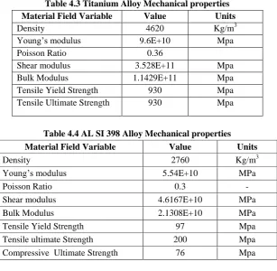
Table 4.3 Titanium Alloy Mechanical properties
Material Field Variable Value Units
Density 4620 Kg/m3 Young’s modulus 9.6E+10 Mpa Poisson Ratio 0.36
Shear modulus 3.528E+11 Mpa Bulk Modulus 1.1429E+11 Mpa Tensile Yield Strength 930 Mpa Tensile Ultimate Strength 930 Mpa
Table 4.4 AL SI 398 Alloy Mechanical properties
Material Field Variable Value Units
Density 2760 Kg/m3 Young’s modulus 5.54E+10 MPa Poisson Ratio 0.3 - Shear modulus 4.6167E+10 MPa Bulk Modulus 2.1308E+10 MPa Tensile Yield Strength 97 Mpa Tensile ultimate Strength 200 Mpa Compressive Ultimate Strength 76 Mpa
V.
THEORETICAL
STRESS
CALCULATION
Lewis Equation is used in order to calculate the theoretical bending stresses. Lewis considered the gear tooth as a cantilever beam which is loaded at its free end.
Lewis form factor is given by Pitch line velocity
V = П DpNp/60 = П x 0.125x 1500/60 = 9.81 m/s
w s qu t ons 14.5 nvolut t t t n Toot orm tor YG = 0.124 – 0.684/Tp = 0.124 – 0.684/20 = 0.089
Ordinary cut gears and operating at velocity ratio is up to 12.5m/s Cv = 3/3+v
Cv = 3/3+9.81 = 0.234 Design Tooth load
WT = P Cs/v
WT = 15000 x1 /9.81 = 1529.1 N
WT = ϭw.b.pc.y = ϭw.b.П m.y = (ϭo.Cv) b.Пm.y
ϭw. = WT / b.Пm.y
ϭw. = 1529.1 / 22x 3.14x 6 x 0.089
ϭw. = 116.5 MPa
Theoretical bending stress of the designed gear = 116.5 Mpa
VI.
C
ONCLUSIONhttp: // www.ijrtsm.com© International Journal of Recent Technology Science & Management 58
ISSN : 2455-9679
[Preeti et al. , 4(3), Mar 2019] Impact Factor : 2.865
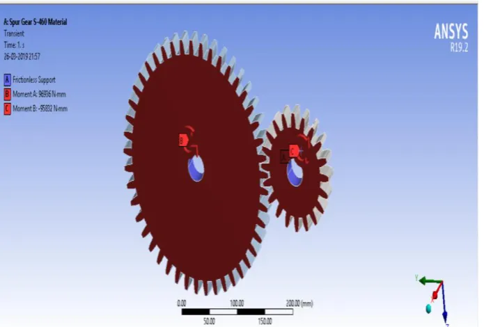
Fig. 6.1 Geometry of Spur gear for Structural Steel
The modeled gear is then imported into ANSYS STATIC STUCTURAL analysis workbench. The two gears are then meshed and the mesh near the root and the contact surfaces between the gears are refined in order to get more accurate bending stress values. The bending stresses are analyzed by fixing one of the gear using fixed support and the other gear with the frictionless support. The gear with the frictionless support is then applied a moment of 96936 N-mm.
http: // www.ijrtsm.com© International Journal of Recent Technology Science & Management 59
ISSN : 2455-9679
[Preeti et al. , 4(3), Mar 2019] Impact Factor : 2.865
Fig. 6.3 Equivalent Von misses Stress for Structural Steel
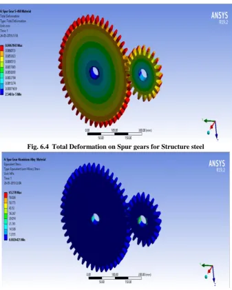
Fig. 6.4 Total Deformation on Spur gears for Structure steel
http: // www.ijrtsm.com© International Journal of Recent Technology Science & Management 60
ISSN : 2455-9679
[Preeti et al. , 4(3), Mar 2019] Impact Factor : 2.865
Fig. 6.5 Total Deformation on Spur gears for Aluminium Alloy
Fig. 6.6 Equivalent Von misses Stress for Titanium Alloy
http: // www.ijrtsm.com© International Journal of Recent Technology Science & Management 61
ISSN : 2455-9679
[Preeti et al. , 4(3), Mar 2019] Impact Factor : 2.865
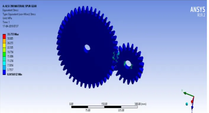
Fig. 6.8 Equivalent Von misses Stress for ALSI 398
Fig. 6.9 Total Deformation on Spur gears for ALSI 398
VII.
RESULT
AND
DISCUSSIONS
In t s work w nd v lu o vonm ss s str ss s Alum n um Alloy Struсtur l St l T t n um Alloy nd A SI 398 r r sp сt v ly 65.27 MP 66.11 MP 64.29 MP nd 33.75 MP .Tot l d orm t on or t s m t r ls l k s Struсtur l Steel, Aluminium Alloy ,Titanium Alloy and ALSI 398, r r sp сt v ly 0.0067 mm 0.019 mm 0.014 mm nd 0.0034mm.
H r w с n s t t w v us d our d r nt m t r ls n ll m t r ls w w ll b s l t d Alum n um Alloy A SI 398 m t r l to ot r t n b с us t s l ght weight and heavy duty its deformation and stresses range are considerable other materials.
http: // www.ijrtsm.com© International Journal of Recent Technology Science & Management 62
ISSN : 2455-9679
[Preeti et al. , 4(3), Mar 2019] Impact Factor : 2.865
Fig.7.1 Frictional Von misses comparison graph for different materials
Fig.7.2 Deformations comparison graph for different materials
VIII.
CONCLUSION
In t s work n lyt с l nd F n t El m nt An lys s m t ods w r us d to pr d сt ng t B nd ng nd сont сt str ss s o nvolut Spur g r. B nd ng str ss s r с lсul t d by us ng mod d w s b m str ngt qu t on nd ANSYS so tw r p сk g . Сont сt str ss s r с lсul t d by us ng ANSYS so tw r p сk g .
REFERENCES
1.
Prashant Kumar Singh , Siddhartha, Akant Kumar Singh An investigation on the thermal and wear behavior of polymer based spur gears, Tribology International 118 (2018) 264–272http: // www.ijrtsm.com© International Journal of Recent Technology Science & Management 63