Performance Analysis of Centrifugal Fan with Airfoil Blade using CFD
1 Chhagan Lal Kharol, 2 Shankar Lal Suthar 1 M.Tech.Scholar, 2Assistant Professor 1, 2 Department of Mechanical Engineering
1, 2Aravali Institute of Technical Studies, Udaipur, Rajasthan, India
1. INTRODUCTION:
The fans are commonly used turbo machines which deliver air at a higher velocity, but at a relatively low static pressure. The pressure rise over a fan is extremely low and is of the order of a few millimeters of water column. The higher limit of pressure rise is of the order of 250mm of water gauge. The increase in static pressure across a blower is relatively higher and is more than 1000mm of water column that is desired to overcome the pressure losses of the gas during its flow through various passages.
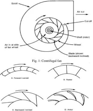
Fig. 1: Centrifugal fan
Abstract: Fans are commonly used turbo machines widely used for the application of cooling, ventilation and air handling. It mainly composed of two parts namely casing and impeller. A casing is the outer body or enclosure which covers the impeller body. Impeller is a rotating member composed of a number of blades on its periphery. A blade may be forward curved, backward curve, radial, inclined or air foil shaped geometry. In the present work two types of air foil blades are analyzed and are being compared for optimal performance. NACA 2412 and NACA 2424 air foil blades are taken for consideration and are analyzed in a virtual environment and numerically. Pressure head versus flow rate curves are obtained for both the geometries and compare theoretical results with obtained from CFD using ANSYS 14.0 fluent workbench.
Centrifugal fans are generally used for high pressure applications. Figure1 shows the useful components of centrifugal fan. A fan mainly composed of an impeller which has blades fixed between the inner and outer diameters. The impeller can be mounted either directly on the shaft extension of the prime mover or separately on a shaft supported between two additional bearings. Air or gas enters the impeller axially through the inlet which provides slight acceleration to the air before its entry to the impeller. The impeller provides swings the gas from a smaller to a larger radius and delivers the gas at a high pressure and velocity to the casing. The flow from the impeller blades is collected by a spiral-shaped casing known as volute casing. The casing can further increase the static pressure of the air and it finally delivers the air to the exit of the fan.
The centrifugal fan impeller can be made by attaching the various types of curved or straight blades to the two sides of the rotor. The casings are constructed with the help of sheet metal of different thickness and steel reinforcing ribs mount on the outside. Appropriate sealing are used between the shaft and the casing. [1]
2. LITERATURE SURVEY:
A large number of researches are being carried out in the field of turbo machinery (Centrifugal Fan) for enhancement of performance characteristics. Some investigation was focused on noise level and frequency of fan. Casing design, impeller design and shape of the blade plays a very predominant role in fan performance. Blade shape is not only used as a passage for air flow but also effects the pressure, efficiency and power input of the fan. Rui Rong et al. studied the centrifugal fan with slots in the blade and cut from pressure side to suction side. Author concluded that slotted technique is effective to reduce blade surface resistance and increases lift force. Which in turn save the energy and improve the characteristic of flow field. Analysis accomplished using computational fluid dynamics. [2] Kishokanna Paramasivam et al. analyzed the noise level in centrifugal fan by guide vanes. In this investigation researcher has modify the leading edge of the guide vane and found that strength of pressure fluctuation and blade passing frequency reduces. Flow pattern studies are done using CFD. [3]. Sheam Chyun Lin et al. investigated backward inclined centrifugal fan for flow visualization, torque estimation and noise analysis using computational dynamics and found that flow trend of fluid makes vital role in the performance of fan that is best matches by CFD Fluent technique. [4] Li Chunxi et al. examined centrifugal fan with enlarged impeller and compare the result with original impeller, numerically and experimentally. Conclusion of the analysis was that total pressure and shaft power increases while efficiency decreases for large impeller. [5] Mao Yijun and Liu Xiaoliang performed experiments on industrial forward curved blade centrifugal fan to check out noise characteristics of the FC centrifugal fan and concluded that good coupled modification advances the fan performance and rise up the operating range. [6] Chintalaa and Gudimetla executed a reverse engineering approach for optimum material evaluation of gas turbine blade using ANSYS FEA package. Blade was analyzed for static structural analysis of different materials at varying centrifugal loads. Author suggested different materials for variety of applications. [7] Supakit Worasinchai et al. analyzed the unsteady Surface Pressures and Airload of a Pitching Airfoil. And interpreted that airfoil motion had significant effects on the surface pressure distribution over the airfoil. [8] The above studies guide us to go ahead and to make some conclusions that computational fluid dynamics approach is a key tool to analyze and solve the various fluid flow problems. FEA gives very close results as compare to the analytical results.
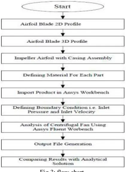
3. METHODOLOGY:
Fig.3: flow chart
4. MODELING AND SIMULATION:
The geometric model of the centrifugal fan is generated using CATIA. Modeling starts from sketching. Locus of blade is being traced by x-y coordinate of airfoil blade and join all the locus point, we get a 2D planer shape as shown in fig 3. Now extrude planer shape upto suitable width, in this case i.e. 30mm, to obtain it into 3D model as shown in figure3. This is our first part which we need.
Model of impeller for with 12 numbers of blades are mounted on the circumference of the impeller. We used a polar array command by choosing rotation command in CATIA work bench. Pictorial view of impeller with airfoil blade is shown in figure 6.
The next important element of our product is casing, which provide divergence shape throughout the periphery of the impeller such that the area is being large in nature from entrance to exit of the fan.
Fig. 6: Model of impeller with airfoil blade
The next important element of our product is casing, which provide divergence shape throughout the periphery of the impeller such that the area is being large in nature from entrance to exit of the fan.
Fig. 7: Model of casing
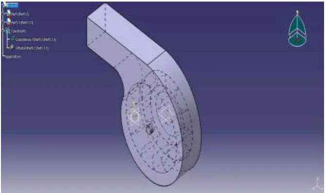
At the last stage of the modeling the tool we have used is coincidence constraints which bring the axis of each part in a collinear direction. The second constraint is offset constraint which is used to provide proper gap between the two surfaces of different components. In this stage complete modeling is ready i.e. shown in figure 8.
5. PROBLEM FORMULATION:
The main objective is to predict the performance of centrifugal fan with two different airfoil blade and visualize the pressure variation and input power. Objective is accomplished by using CFD tool. NACA standard airfoil blades are adopted as the basic blade shape to match the low velocity characteristics of a small fan. As the flow resistance is less on airfoil surface as compared to other types of blades, so airfoil blade is most suitable for aforesaid task. The following input data are taken for calculating the desired numerical values are shown in table1.
Parameter Value
Inlet radius of impeller r1 80mm.
Outlet radius of impeller r2 100mm
Speed of impeller N 1500RPM Width of the blade b 30mm.
Density of air 1.2Kg/m3
Normal component of velocity at inlet is given by the relation
V1n= Q 2πr1b
= 5.684 m/s
Where, Q represents the mass flow rate of air in m3/s. in this case we have taken flow rate is 0.1 m3/s. And r1 represent inlet radius of impeller that is 80mm and b is blade width that is 30 mm.
As no whirl is present at fan inlet so tangential component of velocity is zero at inlet and V1t= 0. Similarly, normal component of velocity at outlet is given by
V2n= Q 2πr2b
= 5.265 m/s
Tangential component of velocity at outlet is given by V2t = V2ntan β2. By calculation we get V2t = 26.52m/s for blade outlet angle 42.21. We will calculate the net head by using the relation given below
H =ω(r2V2t− r1V1t)
g = 42.48 m
Where ω is the angular velocity of impeller in rad/s.
ω =2πN
60 = 157.079 rad
s . Where N is the impeller speed i.e. 1500 RPM.
From above relation we get net head corresponding 0.1 m3/s is 42.48m.
Now to convert to pressure in units of equivalent mm of water column, we multiply by the ratio of air density to water density i.e.
HWC = Hρa
ρw Where ρa is the density of air and ρw is the density of water. Density of air ρa = 1.2 Kg/m3.
Density of water ρw = 998 Kg/m3.
From above relation we get net head is 51.078 m.
Power (P) required to drive the fan can be calculated by using the relation BHP = ρgQH.
Power = 1.2×9.81×0.1×42.48 = 50.02 Watt.
6. CFD ANALYSIS:
Air density (Kg/m3 ) 1.225
Turbulence model used k-ε
Table 2: Boundary conditions for setup
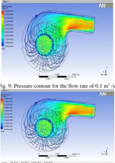
Solution initialization takes place by choosing HIM (hybrid initialization method). Once the solution got processed, we obtained the results in the form of pressure contour. Figure8 represent the pressure contour of centrifugal fan with NACA2412 blade. Contour is plotted for the flow rate of 0.1 m3 /s and impeller speed is 1500 RPM. Pressure
scale is set in Pascal. Maximum intensity of pressure at the fan outlet is 531.2Pa. Red color on the scale indicates the higher pressure that is obtained at fan exit duct. Pressure contour is plotted for the flow rate of air i.e. 0.2 m3 /s for same airfoil blade and boundary condition. Maximum intensity of pressure occurs at fan outlet is 268.40 Pa as shown in figure 9.
Fig. 9: Pressure contour for the flow rate of 0.1 m3 /s.
Fig. 10: Pressure contour for the flow rate of 0.2 m3 /s.
Similar pressure contours are plotted with varying the flow rate of air. Now aforementioned Process is being adopted for the analysis of centrifugal fan with NACA2424 airfoil blade under the same boundary condition and virtual environment. Pressure contour in figure10 represent that the highest pressure occurs at fan exit is in the magnitude of 142.60 Pa for the 0.4 m3 /s flow rate.
Pressure contour for the NACA2424 blade shows the highest pressure i.e. 151.10 Pa occurs at the exit of centrifugal fan for the flow rate 0.5 m3 /s shown in figure 12.
7. RESULT AND DISCUSSION:
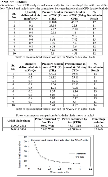
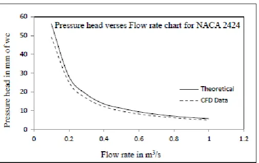
Results obtained from CFD analysis and numerically for the centrifugal fan with two different blades are tabulated below. Table 3 and table4 shows the comparison between theoretical and CFD data for both the blade.
Sr. No.
Quantity delivered of air
in m3/s (Q)
Pressure head in mm of WC (P)
(TH.)
Pressure head in mm of WC (Using
CFD)
% Deviation in
Result
1 0.1 51.078 45.12 12
2 0.2 25.54 22.8 11
3 0.3 17.02 15.01 12
4 0.4 12.32 11 11
5 0.5 10.21 9.12 11
6 0.6 8.51 7.42 13
7 0.7 7.29 6.4 12
8 0.8 6.38 5.6 12
9 0.9 5.67 4.91 13
10 1 5.1 4.51 12
Table 3: Pressure head verses flow rate for NACA 2412 airfoil blade
Sr. No.
Quantity delivered of air in
m3/s (Q)
Pressure head in mm of WC (P)
(TH.)
Pressure head in mm of WC (Using
CFD)
% Deviation in
Result
1 0.1 56.24 49.21 13
2 0.2 28.12 25.11 11
3 0.3 18.74 16.52 12
4 0.4 13.56 12.12 11
5 0.5 11.24 9.78 13
6 0.6 9.37 8.16 13
7 0.7 8.03 7.03 12
8 0.8 7.02 6.12 13
9 0.9 6.24 5.41 13
10 1 5.61 4.82 14
Table 4: Pressure head verses flow rate for NACA 2424 airfoil blade
Power consumption comparison for both the blade shows in table5.
Airfoil blade shape Power consumed by fan (Th.)
Power consumed by fan (CFD)
Percentage deviation
NACA 2412 50.02 Watt 43.71 Watt 12.61%
Fig. 13: Pressure variation with flow rate
8. CONCLUSION:
In this paper the effect of two different NACA series airfoil blade in centrifugal fan were investigated. Two important performance parameter called static pressure and power consumed by fan obtained from CFD analysis and numerical approach are correlated successfully for the cases. In the first case fan with NACA2412 blade adopted and in second case fan with NACA2424 blade consider for investigation. It was found that flow separation and recirculation can be clearly observed in the CFD analysis. The blade profile plays a significant role to reduce flow separation occurs at trailing edge of the fan. Finally, if the blades of centrifugal fans are made of NACA aerofoil section, it can provide better performance to the fans and help in minimizing energy consumption.
9. FUTURE SCOPE:
There are some points which is important from the point of view of the further research and optimization of the fan are given below
1) Carbon fibre is extremely strong and light weight so we can use fan blade material as a carbon fibre reinforced polymer.
2) Volute clearance can be varied for centrifugal fan optimization. 3) We can analyze the fan by varying RPM of the impeller.
4) Noise level and frequency can also be examined. 5) Centrifugal fan can be optimized by varying the number of blades.
REFERENCES:
1. Yahya, S. M. Turbines compressors and fans. Tata McGraw-Hill Education, 2010.
2. Rong, Rui, Ke Cui, Zijun Li, and Zhengren Wu. "Numerical Study of Centrifugal Fan with Slots in Blade Surface." Procedia Engineering 126 (2015): 588-591.
3. Paramasivam, Kishokanna, Srithar Rajoo, and Alessandro Romagnoli. "Suppression of tonal noise in a centrifugal fan using guide vanes." Journal of Sound and Vibration 357 (2015): 95-106.
4. Lin, Sheam-Chyun, and Ming-Lun Tsai. "An integrated performance analysis for a backward-inclined centrifugal fan." Computers & fluids 56 (2012): 24-38.
5. Chunxi, Li, Wang Song Ling, and Jia Yakui. "The performance of a centrifugal fan with enlarged impeller." Energy Conversion and Management 52, no. 8 (2011): 2902-2910.
6. Datong, Qi, Mao Yijun, Liu Xiaoliang, and Yuan Minjian. "Experimental study on the noise reduction of an industrial forward-curved blades centrifugal fan." Applied Acoustics 70, no. 8 (2009): 1041-1050.
7. Chintala, Gopinath, and Prasad Gudimetla. "Optimum material evaluation for gas turbine blade using Reverse Engineering (RE) and FEA." Procedia Engineering 97 (2014): 1332-1340.