Available Online at www.ijpret.com
1
INTERNATIONAL JOURNAL OF PURE AND
APPLIED RESEARCH IN ENGINEERING AND
TECHNOLOGY
A PATH FOR HORIZING YOUR INNOVATIVE WORK
EFFECT OF ADHEREND THICKNESS ON STATIC ANALYSIS OF ADHESIVELY
BONDED DOUBLE LAP JOINTS IN FRP LAMINATED COMPOSITES
JAKEER HUSSAIN SHAIK*, M.L PAVAN KISHORE, GANGADHARUDU TALLA
Research Scholar, Mechanical Engineering Department, National Institute of Technology
Rourkela, India
Accepted Date: 30/12/2013 ; Published Date: 01/02/2014
Abstract: Adhesively bonded joints are increasingly being used in joining various structural components made of FRP laminated composites. Adequate understanding of the behavior of adhesively bonded joints is necessary to ensure efficiency, safety and reliability of such joints. While single lap joint has received considerable attention, very little work has been carried out on the double lap joint configuration. The present investigation deals with the static analysis of adhesively bonded double lap joint in laminated FRP composites using three-dimensional theory of elasticity based finite element method. The finite element model is validated with the theoretical concepts. The double lap joint made of generally orthotropic laminates subjected to longitudinal loading is analyzed. The out-of-plane normal and shear stresses are computed at the interfaces of the adherend and adhesive, and at mid surface of the adhesive for different ply orientations by varying the thickness of adherend is considered for the analysis. It was predicted that when the fiber angle increases the stiffness of the plate in the longitudinal direction decreases and the interlaminar stresses at joint interfaces increases due to the effect of coupling and also the longitudinal displacement increases.
Keywords: Double lap joint (DLJ), Finite element method (FEM), Fiber-reinforced polymer (FRP), Interlaminar stresses, Adherend thickness.
Corresponding Author: JAKEER HUSSAIN SHAIK
Access Online On:
www.ijpret.com
How to Cite This Article:
Available Online at www.ijpret.com
2
INTRODUCTION
Fiber-reinforced polymer (FRP) composites are increasingly replacing metals in primary load-carrying members, resulting in many advantages, but also introducing new challenges. Because no structure is built as a single monolithic unit, various members must be joined adequately to ensure the structure’s safety and performance. Unlike metals, structural thermoset-FRP members cannot be welded, and lack the ductility needed for efficient mechanical fastening, making adhesive-bonding the only efficient alternative. However, an adequate understanding of the behavior of adhesively bonded joints is necessary to ensure not only efficiency, but also safety and reliability.
The overwhelming majority of the work on the subject of adhesive bonding has focused on the single-lap configuration. The use of mechanical fasteners to join composite structures is widespread in the aerospace industry. The tolerance to environmental effects, the ease of inspection and assembly, and the possibility of part replacement are the main advantages of this technique. However, even for optimized combinations of laminate lay-up, stacking sequence and joint geometry, low efficiencies, defined as the ratio between the notched and unnotched strength of the laminate, occur. The low efficiency is due to high stress concentrations, and to the brittle nature of most fiber-reinforced composites. Low efficiencies lead to weight and cost penalties in composite structures.
Available Online at www.ijpret.com
Available Online at www.ijpret.com
4 transverse normal stresses in the joint related to the peel stress. Gustafson and Waas [16] developed a thermo-mechanical analytical model and a corresponding macroscopic bonded joint finite element for the analysis of orthotropic double lap joints subjected to combined thermal-mechanical loads. Mokhtari et.al [17] studied the effects of composite layer stiffness, thickness and ply orientations on stresses in the adhesive layer of a double lap bonded joint are investigated using three-dimensional finite element analysis. Non-linear behavior of the adhesive is considered for different ply orientations to find the maximum stress in adhesive joints. Choupani [18] carried out a finite element study to understand the stress fields and stress intensity factors over the behavior of cracks in adhesively bonded double-lap joints. From the finite element results it was found that the patch materials of low stiffness, low adhesive module and low tapering angles are desirable for a strong double-lap joint aerospace structure. Vallee et al [19] carried out the experimental and numerical investigations were carried out on adhesively bonded full-scale double lap joints composed of pultruded GFRP profiles with relatively thick adhesive layers. The influence of different geometric parameters on the joint strength was investigated for different adhesive layer thickness, the fillet radius and the overlap length. Kim et al [20] present the behavior of a two-part epoxy adhesive bonded to a steel substrate subjected to cold region environment. Experimental tests are conducted for various specimens using double-lap shear joints in wet–dry and freeze–thaw conditions to examine the durability performance of the joint, including load-carrying capacity, interface deterioration, and failure mode.
Available Online at www.ijpret.com
5
2. PROBLEM MODELING
The details of geometry, finite element model with validation, stacking sequence of the laminate, type of load applied along with boundary conditions and material properties used for the static analysis of double lap joint are as follows.
2.1 Geometry
The geometry of the double lap joint used for the present analysis is as shown in Fig.1.
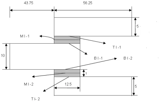
Fig. 1 Geometry of the double lap joint (All the dimensions are in mm)
The total length of the adherend is taken as 100mm and width of the adherend is taken as 25mm. The adhesive thickness is 1mm. The overlap length for the geometry is taken as 12.5 mm. The value of thickness of the adherend (tan) is determined from the length to thickness ratio (s) equal to10.
In Fig.1 TI-1, TI-2, BI-1 and BI-2 represents the adherend and adhesive Interfaces at top and bottom of the double lap joint about middle adherend. MI-1 and MI-2 represents the Interfaces at middle of the adhesive at top and bottom of the double lap joint about middle adherend. According to these dimensions a geometric model is prepared by using ANSYS software and Finite Element mesh is done as per the geometric modeling.
2.2 Finite Element Modeling
Available Online at www.ijpret.com
6 element is defined by eight nodes having three degrees of freedom per node: translations in the nodal x, y, and z directions. SOLID45 element is used for the structural analyses of the joint considered for the present analysis.
Fig.2 SOLID45 Element
2.3 Loading and Boundary Conditions
The following types of loads and boundary conditions are applied for prediction of the response of the structure in the present analysis.
Loading: A uniform longitudinal load of 10Mpa is applied at the non clamped end of DLJ in the
present analysis.
Boundary Conditions: One end of the joint is clamped and the other end is restricted to move
in the transverse direction.
2.4 Material Properties
The following mechanical properties are used for the present analysis of double lap joint.
i) Epoxy (adhesive)
E = 5.171 GPa; ν = 0.35;
ii) Graphite-Epoxy (adherends)
E1 = 172.72 GPa, E2 = E3 = 6.909 GPa
Available Online at www.ijpret.com
7
2.5 Laminate sequence
+θ0/-θ 0/-θ 0/+θ 0 laminated FRP composite plates are used as adherends for the present analysis. The value of θ is measured from the longitudinal direction of the structure (x-axis) and varied from 00 to 900 in steps of 150.
3. RESULTS AND DISCUSSION
3.1 Validation of the finite element model.
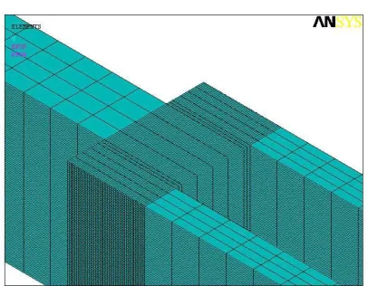
Fig. 3 shows the finite element mesh on the overlap region of the double lap joint. The finite element mesh divisions on the non overlap regions are same as that given for overlap region across thickness, but along the length coarse mesh is considered to limit the number of nodes without loosing the accuracy of the solution. The present finite element model is validated by comparing the stresses obtained for the double lap joint of especially orthotropic laminates with the theoretical concepts. A few computed values of stresses on free surfaces of the present finite element model are obtained after conducting number of convergence tests by varying mesh size. The values of interlaminar stresses are observed to be nearly equal to zero at all free surfaces.
Table1. Validation of the finite element model for double lap joint
POSITION VALUE OF STRESSES ON FREE SURFACES
X( mm) Z (mm) σzz (Mpa) τzx (MPa) τyz (MPa)
0 6 -0.00041834 -0.0063767 0.30015E-09
12.5 6 0.0068800 0.000068355 -0.19124E-09
34.75 6 0.00024352 0.00030971 -0.19156E-10
56.25 6 0.00010073 -0.0098682 -0.49716E-10
-21.875 0 -0.000094385 0.0077292 0.31930E-10
Available Online at www.ijpret.com
8 Fig. 3 Finite element mesh on the overlap region of the double lap joint
3.2 Variation of stresses and displacement with fiber angle at tan = 10mm.
Figs. 4-7 show the variation of the stresses and displacement with respect to θ for longitudinal loading. The normal stress, σzz (Fig.4) increases with increase in θ up to 450 and later decreases at all the surfaces under consideration. It is also observed that the stresses are same at the top and bottom interfaces and their value is more at middle surface of the adhesive. As the fiber angle increases, the stiffness of the plate in the longitudinal direction decreases and the stress increases. The reduction of the stresses beyond θ = 450 may be due to the effect of coupling.
Fig. 5 shows the variation of τyzwith respect to θ. This stress also increases up to θ = 450 and later decreases. The magnitude τyz is small at top interface compared to bottom interface and mid interface. However the magnitudes of these stresses are less when compared to σzz at all fiber angles under consideration.
Fig. 6 shows the variation of τzx with respect to θ. This stress at all the interfaces increases up to θ= 450, and later decreases. The magnitude τzx is small at bottom interface followed by top interface and middle interface. The magnitude of stress at all the interfaces is more for τzxand σzzwhen compared to τyz.
Available Online at www.ijpret.com
9 Fig.4.Variation of σzz with θ (tan= 10mm) Fig.5. Variation of τyz with θ (tan = 10mm)
Fig.6. Variation of τzx with θ (tan = 10mm) Fig.7. Variation of u withθ (tan = 10mm)
3.3 Variation of stresses and displacement with adherend thickness at fiber angle
θ = 450
Available Online at www.ijpret.com
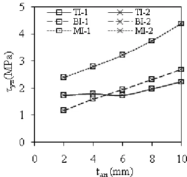
10 Fig. 9 shows the variation of τyz with tan. The magnitude τyz is small at top interface followed by bottom interface and mid interface. However the magnitude of these stresses is slightly more at top interface compared to stresses at bottom interface upto 5mm thickness of the adherend. The magnitudes of the stresses are less at all interfaces when compared to σzz.
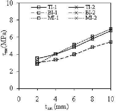
Fig. 10 shows the variation of τzx with tan. This stress increases as the adherend thickness increases. The magnitude τzx is small at bottom interface followed by top interface and mid interface. The magnitude of stress at the interfaces is more for τzx and σzzwhen compared to τyz.
Fig. 11 shows the variation of longitudinal displacement ‘u’ with adherend thickness. There is a slight decrease in ‘u’ upto 4mm thickness, and then increases at a greater rate between 4mm to 6mm followed by a slight increase.
Fig. 12-15 represent the deformed shapes of the double lap joint for the fiber angle of θ =450.
Available Online at www.ijpret.com
11 Fig 10. Variation of τzx with tan Fig 11. Variation of u with tan
Available Online at www.ijpret.com
12 Fig.13 Interlaminar shear stress in τyz direction
Fig.14 Interlaminar shear stress in τzx direction
Available Online at www.ijpret.com
13
4. CONCLUSIONS
Three dimensional theory of elasticity based finite element analysis has been carried out for the static analysis of adhesively bonded double lap joint in laminated fiber reinforced plastic (FRP) composites. In the present analysis the effect of Interlaminar normal stress (σzz), interlaminar shear stresses (τyz, τzx) and displacement in angle-ply laminates is determined for the different cases of the adherent thickness of the double lap joint. From all the above cases it was predicted that maximum value of the interlaminar stresses for the joint regions occurs particularly at fiber angle θ = 450.The following reasons are concluded from the part of this analysis.
The magnitude of stresses σzz, τyz and τzx increases upto θ = 450 and later onwards it decreases. As the fiber angle increases the stiffness of the plate in the longitudinal direction decreases and the stress increases. The reduction of the stresses beyond θ = 450 may be due to the effect of coupling.
The increase in the longitudinal displacement is due to the reduction of the stiffness with increase in fiber angle. Variations up to 300 and beyond 600 may be due to the effect of coupling.
The magnitude of stress at all the interfaces is more for σzzand τzx when compared to τyz.
The magnitude of stresses σzz, τyz, τzx and ‘u’ increases with increase in thickness of the adherend. A similar trend is maintained by the stresses σzz, τyz and τzx for all the values of adherend thickness under consideration.
The increase in longitudinal displacement and stresses is due to the reduction of stiffness of the plate in the longitudinal direction with increase in fiber angle.
The peel stress, σzz, found to be the deciding parameter in design of adhesive bonded double lap joints as the magnitude of this stress is greatest when compared to other stresses.
Available Online at www.ijpret.com
14
Nomenclature
EL = E1 Young’s modulus of the lamina in the fiber direction
ET = E2 = E3 Young’s modulus of the lamina in the transverse direction of the fiber
GLT = G12 = G13 Shear modulus in the longitudinal plane of the fiber
GTT = G23 Shear modulus in the transverse plane of the fiber
νLT = ν12 = ν13 Poisons ratio in the longitudinal plane of the fiber
νTT = ν23 Poisons ratio in the transverse plane of the fiber
tan Adherend Thickness
θ Fiber Angle
REFERENCES
1. Volkersen O, Die Niektraftverteilung in Zugbeanspruchten mit Konstanten Laschenquerschritten, Luftfahrtforschung, 1938, pp. 41–47
2. Goland M, Reissner E, The Stresses in Cemented Joints, ASME Trans., Journal of Applied Mechanics, 1944, pp. 17–27
3. Hart-Smith L, Adhesive-Bonded Single Lap Joints, NASA-CR-112236, 1973
4. Hart-Smith L, Adhesive-bonded Double Lap Joints, NASA-CR-112235, 1973
5. Kim H, Kedward K, Stress analysis of adhesively bonded joints under in plane shear loading, J. Adhesion, 2001, pp. 1-36
6. Penado FE, Dropek RK, Numerical design and analysis, Engineered materials Hand book, 3, Adhesives and Sealants, ASM International, 1990
7. Abdolmajid S, Yousefsani M T, Accurate determination of stress distributions in adhesively bonded homogeneous and heterogeneous double-lapjoints, European Journal of Mechanics A/Solids, 2013, pp.197-208
Available Online at www.ijpret.com
15 9. Panigrahi SK, Pradhan B, Three dimensional Failure analysis and damage Propagation behavior of Adhesively bonded Single lap joints in laminated FRP Composites, Journal of Reinforced plastics and Composites, 2007, pp. 183-201
10. S.K. Panigrahi, B. Pradhan, Onset and growth of adhesion failure and delamination induced damages in double lap joint of Laminated FRP composites, Composite Structures, 2008, pp. 326–336
11. S.K. Panigrahi, B. Pradhan, Through-the-width delamination damage propagation characteristics in single-lap laminated FRP composite joints, International Journal of Adhesion & Adhesives, 2009, pp. 114–124
12. Ascione F, Ultimate behaviour of adhesively bonded FRP lap joints, Composites: Part B, 2009, pp. 107–115
13. De Castro J, Thomas Keller, Ductile double-lap joints from brittle GFRP laminates and ductile adhesives, Part I: Experimental investigation, Composites: Part B, , 2008, pp. 271–281
14. Chen WT, Nelson CW, Thermal Stress in Bonded Joints, IBM J. RES. DEVELOP, 1979, pp. 179-188
15.Osnes H, McGeorgeb D, Analysis of overlaminated double-lapjoints, Journal of Composites :PartB, 2005, pp. 544–558
16. Peter A, Gustafson A, Waas M, A Macroscopic Finite element for a symmetric double lap joint subjected to mechanical and thermal loading, 16th International conference on composite materials, Japan, 2007
17. Mokhtari M, Madani K, Belhouari M, Touzain S, X. Feauga, Ratwani M, Effects of composite adherend properties on stresses in double lap bonded joints, Journal of Materials and Design, 2013, pp. 633–639
18. Choupani N, Characterization of fracture in adhesively bonded double-lap joints, International Journal of Adhesion & Adhesives, 2009, pp. 761–773
Available Online at www.ijpret.com