544
Copyright © 2011-15. Vandana Publications. All Rights Reserved.
Volume-5, Issue-2, April-2015
International Journal of Engineering and Management Research
Page Number: 544-550
Finite Element Analysis of Alloy Wheel
S. Phani Kumar1, M. Raja Roy2, M. Sailaja3 1, 2,3
Department of Mechanical Engineering, Anil Neerukonda Institute of Technology and Sciences, INDIA
ABSTRACT
Automobile wheels have in the time period spanning the last five decades progressively evolved from the early spoke design of wood and steel the carryovers from wagon and bicycle technology, flat steel discs, and more recently stamped metal configurations. The metal configurations are made from either cast or cast plus forged aluminum alloys in the present and newer generations of ground vehicles. This project work summarizes the application of Finite Element Techniques for analyzing stress and displacement distribution in vehicle wheels subjected to the conjoint influence of inflation pressure and radial load. Wheel strength with regard to the fractures on edges and other critical points when the wheel strikes an obstacle shall be checked. In order to show the sufficient resistance to fractures it is necessary to carry out an impact test. An impact load (as per SAE standards) is applied on the wheel at a determined angle. The modal analysis is carried out for observing the natural frequencies. Static analysis for the given radial load and the angular velocities of 40, 60, 80, and 120, with the appropriate constraint set of conditions in order to check the wheel strength. Yield strength of the alloy wheel material is checked with the Von-Mises stress obtained, (as per the ISO 7141 - Road Vehicles - Wheels - Impact Test Procedure, and SAE J175 - Impact Test Procedures standards). Therefore the study states that the innovative design of the wheel is safe for its operating conditions for the given loads specified.
Keywords— Alloy wheel, impact load, modal analysis, NASTRON
I.
INTRODUCTION
Wheel is an important structural member of the vehicular suspension system that supports the static and dynamic loads encountered during vehicle operation. Since the rims, on which cars move, are the most vital elements in a vehicle, they must be designed carefully. Safety and economy are particularly of major concerns when designing a mechanical structure so that the people could use them safely and economically. Style,
weight, manufacturability and performance are the four major technical issues related to the design of a new wheel and/or its optimization. The wheels are made of either steel or cast/forge Aluminium alloys. Aluminium is the metal with features of excellent lightness, corrosion resistance, etc. In particular, the rims, which are made of Aluminium casting alloys, are more preferable because of their weight and cost.
Automotive manufacturers have been developing safe, fuel efficient and lightweight vehicular components to meet governmental regulations and industry standards (Stearns, 2000). In the real service conditions, the determination of mechanical behavior of the wheel is important, but the testing and inspection of the wheels during their development process is time consuming and costly. For economic reasons, it is important to reduce the time spent during the development and testing phase of a new wheel. A 3–D stress analysis of Aluminium wheels of the car involves complicated geometry. Therefore, it is difficult to estimate the stresses by using elementary mechanical approximations. For this purpose, Finite Element Analysis (FEA) is generally used in the design stage of product development to investigate the mechanical performance of prototype designs.
FEA simulation of the wheel tests can significantly reduce the time and cost required to finalize the wheel design. Thus, the design modifications could be conducted on a component to examine how the change would influence its performance, without making costly alteration to tooling and equipment in real production.
1.1 Types of Wheel/Rim
Steel and light alloy are the main materials used in a wheel however some composite materials including glass-fiber are being used for special wheels.
545
Copyright © 2011-15. Vandana Publications. All Rights Reserved.
Fig: 1.1 Wheel Nomenclature1.2 Material Properties of the Alloy – 2024-T351 Al plate (Aluminum Alloy)
Subcategory: Aluminum Alloy; Nonferrous Metal;
Aluminum Casting Alloy: Aluminum Alloy – 2024-T351
Composition:
Table: 1.1 Aluminum Alloy Material Data
Component Wt% Componen
t Wt%
Al 90.7 - 94.7 Mn 0.3 – 0.9
Cu 3.8 - 4.9 Si Max 0.5
Fe Max 0.5 Ti Max 0.15
Mg 1.2 – 1.8 Zi Max 0.25
Tensile Yield strength = 324 Mpa Ultimate Tensile strength = 420Mpa Compressive stress = 400Mpa Young’s modulus = 73.1 GPa Density = 2.78 gm/cc Poisson’s ratio = 0.33
II.
LITERATURE REVIEW
Dhananjay S. Shinde [1] this paper reveals the
use of FEA for design and development of an alloy wheel for passenger car for Indian OEM. It describes the complete design process from modeling to testing of 14 inch 5.5 j type alloy wheel as per tire and rim association. This paper captures a complete design process of typical automotive component and how to reduce complexity and
computational time with increasing accuracy for better solution with the help of strong analytical tools. Liangmo
Wang*-Yufa Chen –Chenzhi Wang [2] this paper
reveals the “Fatigue Life Analysis of Aluminum Wheels by Simulation of Rotary Fatigue Test” To improve the quality of aluminum wheels a new method for evaluating the fatigue life of aluminum wheels is proposed in this paper. The fatigue life of aluminum wheels was predicted by using the equivalent stress amplitude and aluminum alloy wheel S-N curve. The results from the aluminum wheel rotary fatigue bench test showed that the baseline wheel failed the test and its crack initiation was around the hub bolt hold area that agreed with the simulation. The results indicated that the proposed method of integrating finite element analysis and nominal stress method was a good and efficient method to predict fatigue life of aluminum wheels. N. Satyanarayana & Ch. Sambaiah [3] In this paper a detailed “Fatigue Analysis of Aluminum Alloy Wheel under Radial Load”. During the part of project a static and fatigue analysis of aluminum alloy wheel A356.2 was carried out using FEA package. The finite element idealization of the model was then produced using the 10 noded tetrahedron solid elements. The analysis was performed in a static condition. The pressure is applied on the rim. The total deformation, alternative stress and shear stress by using FEA software are found. Also the life, safety factor and damage of alloy wheel by using S-N curve are determined. M.V. Prabha and
Pendyala Verra Raju [4] in this paper design and
development of aluminum alloy wheels is conducted. The aluminum alloy wheels provide better heat conduction and typically lighter for the same strength. When analyzing the stress and the displacement distribution in vehicle wheels subjected to conjoint influence of inflation pressure and the radial load this project work generalizes the specifications of FEA analysis techniques. The effect of tire air pressure in conjunction with radial load is examined. J. Steams, T.S. Srivastan, X. Gao, and P.C.
Lam [5] In this paper “Understanding the Influence of
Pressure and Radial loads on Stress and Displacement Response of a Rotating Body: The Automobile Wheel is done. This paper highlights the use of the finite element technique for analyzing stress and displacement distribution in which of automotive vehicles when subject to the conjoint influence of inflation pressure and radial load. A potentially viable technique for finite element modeling of radial wheel, subjected to loading is highlighted. The extrinsic influence of inflation pressure on performance of the rotating body, that is, the wheel, is rationalized.
III.
OBJECTIVE OF THE PROBLEM
546
Copyright © 2011-15. Vandana Publications. All Rights Reserved.
The project mainly involves in modeling of the wheel using CATIA, and the analysis is performed on the modeled component using NASTRAN. Analysis that is performed typically includes static analysis; modal analysis; and transient analysis.
3.1 Scope of the Project
The project work deals with finding out natural frequency of Alloy wheel using modal analysis and stresses induced in the structure due to static load conditions and time varying loads using static analysis and transient dynamic analysis. Static or dynamic analysis can tell us about stress, displacement, acceleration etc. but not how long the component will survive.
3.2 Types of load
There are four different loads acting on the wheel rim 1.Radial Load
2.Tire Pressure 3.Centrifugal Load 4.Combined Load
Fig: 3.1 Schematic Diagram of Radial Loading Conditions
3.3 Design Calculations Radial endurance test
The radial load to be imparted in the test shall be in accordance with the following formula:
Fr = F * k Where
Fr = Radial load in N
F = the maximum load coming on to the tire in N K = Coefficient according to the industrial standards According to the industrial standards
F = 1400 lbs
= 1400 * 0.453 = 634.2 kg = 634.2 * 9.81
= 6221.5 N k = 2.25 Radial load Fr = F * k
= 6221.5 * 2.25 = 13998.375 N
Centrifugal load
Angular velocity is calculated by using the following formula.
From the relation
V = r * ω
Where
V = velocity of the car in m/s r = radius of the tire in m
ω = Angular velocity in rad/s V = r * ω
Given Speeds:
The wheel is taken at various speeds for analysis, these speeds are;
a) 40kmph
b) 60kmph
c) 80kmph
d) 120kmph
a) v = 40 kmph; r = 184 mm = 0.184 m. Therefore;
5/18*40 = 0.184 * ω
ω = 5/18*40 / 0.184 = 60.38 rad/sec. b) v = 60 kmph; r = 184 mm = 0.184 m.
Therefore;
5/18*60 = 0.184 * ω
ω = 5/18*60 / 0.184 = 90.579 rad/sec. c) v = 80 kmph; r = 184 mm = 0.184 m.
Therefore;
5/18*80 = 0.184 * ω
ω = 5/18*80 / 0.184 = 120.77 rad/sec. d) v = 120 kmph; r = 184 mm = 0.184 m.
Therefore;
5/18*120 = 0.184 * ω
ω = 5/18*120 / 0.184 =181.16 rad/sec.
IV.
MODELING AND ANALYSIS
We can use the software of CAD (Computer Aided Design) to complete the three-dimensional parametric modeling of gears. Using the functionality of three dimensional solid modeling software it is easy to implement parametric gear drive and it also has a good interface with the Finite Element Software.
547
Copyright © 2011-15. Vandana Publications. All Rights Reserved.
CATIA application. It familiarizes you with the commonly used functions of CATIA.
The method of Alloy Wheel geometry and parametric modeling is as follow,
• Determining the basic parameter • Determining the geometric parameter • The characteristic parameter
In CATIA the generated model geometry is opened in NASTRON for analysis.
The Alloy Wheel which was created CATIA is imported to NX Nastran for Static and dynamic analysis. It is done by saving drawing in STEP or IGES file format in CATIA.
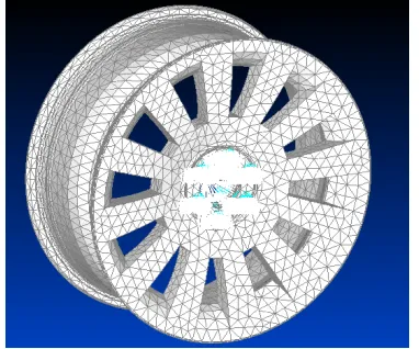
Fig: 4.1 Meshing and Master Node of Alloy Wheel
4.1 Boundary Conditions for Static Analysis and modal analysis:
6 P.C.D holes : Constrained for 5 (UX, UY, UZ, RX, RZ) degree of Freedom, (Rotation in Y direction is set free)
Force applied : On bead seat Analysis type : Static (Steady State)
Fig: 4.2 Boundary condition in static analysis (both pressure and radial loads)
4.2 Boundary Conditions for Transient Analysis
• 6 PCD Holes : Fully constrained • Force Applied : On bead seat • Analysis type : Transient (Impact) • Solution method : Full method
• Type : Force and time • Load steps : Two (First Step10,
Second Step50)
• Output controls : Every sub step
Fig 4.3 : Boundary conditions are applied on the surface of the wheel
V.
EVALUATION AND RESULTS
5.1 Results of static structural analysis Solid Von Mises stress:
548
Copyright © 2011-15. Vandana Publications. All Rights Reserved.
Fig: 5.2 Total Deformation is 0.0000152mm whenpressure is acting alone.
AT 40 KMPH
Solid Von Mises Stress:
Fig: 5.3 Solid Von Mises stress is 77.86Mpa in static structural analysis.
Below Data represents the Equivalent Stress and Total Deformation at Defined Speeds.
TABLE: 5.1 Equivalent Stresses and Total Deformation at Defined Speeds.
SPEED (in kmph)
EQUIVALENT STRESS
(M Pa)
TOTAL DEFORMATION
(mm)
40 77.86 0.0000152
60 103.4 0.0000152
80 129 0.0000151
120 167.3 0.0000151
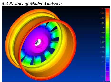
5.2 Results of Modal Analysis:
Fig: 5.4 Mode shape 8 (at frequency of 948.0643Hz) deformation is 5.413mm
Table 5.2 shows modal analysis results
Minimum Deformation is 0 mm
Mode
Shape Deformation
Reported frequency in Hz
1 12.96 418.0931
2 12.98 418.24
3 8.332 514.7781
4 8.297 516.7995
5 14.09 649.1738
6 14.1 649.331
7 6.134 689.7253
8 5.413 948.0643
9 15.27 1042.798
5.3 RESULTS OF DYNAMIC ANALYSIS OF ALLOY WHEEL:
Solid Von Mises Stress
549
Copyright © 2011-15. Vandana Publications. All Rights Reserved.
Total Deformation:Fig: 5.6 Total Deformation is 0.00102mm in Transient Dynamic Analysis
Input Sine Load Curve For Transient Dynamic Analysis:
Fig: 5.7 Input Graph For Transient Dynamic Analysis
Output Sine Load Curve in Transient Dynamic Analysis:
Fig: 5.8 Output Graph For Transient Dynamic Analysis
The above plot is obtained for two elements i.e. for elements 29586 and 22867. The maximum stress of the element 29586 is 199.8Mpa and the maximum stress of the element 22867 is 11.75Mpa respectively.
5.4 RESULTS SUMMARY
In static analysis, after completion of meshing we apply inflation pressure 0.246 M Pa at rim along with a radial load of 13998.375N, Maximum displacement occurred is 0.00102mm and minimum is 0.0000151mm.
In model analysis, the mode shapes of aluminium alloy wheel are obtained at different frequencies thus checking the resonance effect of the alloy wheel.
In transient dynamic analysis, maximum stress value is 238.3mpa which is less than the ultimate stress of aluminum alloy wheel, hence proving that the design is safe.
When radial load along the circumferential direction is assumed to follow sine function distribution, graph is obtained with time sets on x-axis and solid Von-Mises stress on y-x-axis which shows the variation of stress with respect to time sets for different elements. The maximum stress values of the elements 29586 and 22867 are 199.8Mpa and 11.75Mpa. The wheel safety is maximum at the hub portion because maximum load is acting at the rim. Minimum load is acting at the hub. Finite element analysis is carried out by simulating the test conditions to analyze stress distribution, total deformation in the alloy wheel. The safety factor obtained from the results shows that the design is safe.
VI. CONCLUSION AND FUTURE SCOPE
The modeling and analysis for the wheel rim is carried out successfully and satisfactorily. The wheel is analyzed for Radial endurance test.
In radial endurance test three conditions are checked. a. Pressure loading
b. centrifugal loading c. Vertical loading.
The wheel is constrained appropriately and the loads are calculated based on the specifications and applied to appropriate nodes. The wheel is analyzed for the calculated loading condition and the stress plot is obtained. In the case of pressure loading along with radial load, Solid Von Mises stress obtained shows the maximum stress the wheel experiences under the pressure load and on the portion of the rim there is a gradual transition from compression to tension. In case of centrifugal loading the stress distribution and total deformation at different speeds are obtained and the plot shows that the design is safe. When a section plot is taken it will show a gradual transition from tension to compression.
By the experimental data the alloy wheel displacement lies within 7.5 mm.
550
Copyright © 2011-15. Vandana Publications. All Rights Reserved.
From the analysis, finally, it can be concluded that as the speed increases Stress, displacement increases and life decreases.
FUTURE SCOPE
The file, which is created in NASTRAN, is equivalent with the provision for flexibility by which stress can be modified to suit any possible situation that may arise in future. The linear static stress analysis is performed for the present wheel rim. The future work involves different types of analysis such as
1. Fatigue Test 2. Fluent Analysis
3. Couple Field Analysis etc…
REFERENCES
[1] Safraz K. Naikwadi - “Design and Development of an Alloy Wheel for Passenger Car-FEA Approach”.
[2] J. Steams, P.C. Lam and T.S. Srivatsan, “An Analysis of stress and displacements distribution in rotating rim is subjected to pressure and radial load”, university of Texas, Austin, pp 1-5
[3] SAE J175-1970-Passenger Car-Impact Performance Requirements and Test Procedure.
[4] K. Morita and M. Kawashima, “Finite element stress analysis of a car wheel,” Sumitomo Metals, vol.39, no.3, pp.245-263, 1987.
[5] R S Khurmi, Gupta (1997), “Theory of Machines”, Eurasia Publishing House Pvt. Ltd. NEW DELHI, pp640-650.
[6] IS 9436:1980-Performance Requirements and Methods of tests for Wheel for Passenger Cars.
[7] K. Morita and K. Ishihara, “Finite element analysis of a steel car wheel,” Sumitomo search, no.35, pp.89-106, 1987.
[8] The Tire and Rim Association, 1998 Yearbook.