Data driven control topology for industrial process
using PLC
Sumit B. Jadhav
Electronics and Telecommunication Engineering Sardar Patel Institute of Technology
Andheri (W) -Mumbai, India [email protected]
S. S. Rathod
H.O.D. Electronics Engineering Sardar Patel Institute of Technology
Andheri (W) -Mumbai, India [email protected]
P. V. Kasambe Electronics Engineering Sardar Patel Institute of Technology
Andheri (W) -Mumbai, India [email protected]
Abstract—This paper presents the design and implementation of the data driven control topology of the industrial process. The industrial process under consideration is particularly engine room and office room of an industrial building. The data driven control topology is used for an energy efficient management of this industrial process using programmable logic controllers (PLC). In this paper, data driven control through parameter monitoring are used to access the data, through which the various sub-processes of this process are controlled. The parameters considered here are temperature of the engine room, office room and the number of persons present in the office room, etc. To demonstrate this control scheme, the model of the industrial process is proposed which consists of two parts i.e. office room and engine room. In the engine room, data driven control topology is demonstrated only for controlling the temperature of an engine room by varying the speed of 3ϕ Induction Motor (IM) which ultimately varies the speed of ventilation fan driven by it. Feedback from a temperature sensor is compared with the set point and manipulated error from PID controller is given to variable frequency drive (VFD) to control speed of 3ϕ IM. In office room, LDR sensors at the door and PIR sensor are used to sense and count the number of persons present in the office room and by using this value of count, all the electrical appliances of that office room will be switched ON or OFF. Here the results of the data driven control topology is presented for the working of speed control of 3ϕ IM and ON/OFF action of the electrical appliances using a PLC.
Keywords— PID Controller; PLC; VFD; HMI.
I. INTRODUCTION
Energy is the foundation of everything we do. All of us use energy every day—for cooking, transportation, heating and cooling rooms, manufacturing, lighting. We depend on energy to make our lives comfortable, productive. To maintain our quality of life, we must use our energy resources precisely.
Energy conservation is any form behavior that results in the use of less energy, whereas Energy efficiency is the use of different technology that requires less energy to perform the same task. Heating and cooling systems use more energy as compared to any other systems in our homes as well as in many industries. In this paper, we are using programmable logic controllers (PLC) with variable frequency drive (VFD) for energy efficient management using data driven control topology.
In order to optimize energy management, based on the analysis of different kinds of scenarios, for ventilating, heating, lighting system, etc. in an industrial building, the corresponding sub-systems are realized respectively with two alternative modes i.e. automatic mode and manual mode [1]. The idea of computerized control and its application saves precious time and manual effort, which can be utilized for better purposes [2] [3]. Monitoring and control of ON/OFF status of the different electrical appliances present in the industry are explained in [4] The data driven controlling method for engine room of marine vessels through parameter monitoring to adjust the variation of combustion air flow requirement in order to optimize energy efficiency [5].
Volume 3, Special Issue 1, ICSTSD 2016 Hence this paper demonstrates the design and
development of data driven control topology which can be used energy efficient management of an Industrial process. In this control topology, different parameters of the process are monitored and accordingly PLC will take appropriate action which is programmed using Ladder Logic programming language for executing the control algorithm developed.
The rest of the paper is organized as follows. Section I is the introduction to the data driven control topology. Section II explains the hardware and software used in the data driven control system. The description of the data driven control topology used in the work done is explained in section III. Final results are presented in section IV. In section V Conclusion and future work is given.
II. HARDWARE AND SOFTWARE DESCRIPTION
A. Hardware
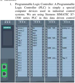
1. Programmable Logic Controller: A Programmable Logic Controller (PLC) is simply a special computer devices used in industrial control systems. We are using Siemens SIMATIC S7-1500 series PLC in this data driven control
topology. Fig.1 shows Siemens S7-1500 CPU with its digital and analog input as well as output model and is can further expanded easily. The SIMATIC S7-1500 CPU's offer best performance with excellent usability. The CPUs are prearranged for numerous applications in automation engineering with their PROFINET / PROFIBUS interfaces, integrated functionalities, such as PID controller, Motion Control and temperature controller, trace support.
2. Variable frequency drive: VFD is a type of adjustable-speed or frequency drive used for
electro-mechanical drive systems to control induction motor speed and it is done by varying motor input parameters i.e. frequency and voltage. Here we are using Siemens SINAMICS G120C VFD in this data driven control topology. Many static speed motor applications that are supplied with AC line power can save energy when they are operated at variable speed.
3. Human-Machine Interface (HMI): HMI is the space where interactions between humans and machines occur. It is cost-efficient operation and monitoring of simple applications. We are using Siemens SIMATIC HMI Basic Panel KTP400 Basic 2nd Generation with 4" display. By using this we going to specify set point to PID, we can see count value of number of person present in the office room, etc.
4. Sensors: For data driven control, here we are using two light dependent resistance (LDR) at the door in the office room, PIR sensor in the office room and temperature sensor i.e. PT100 RTD is used in both office room as well as in the engine room. Working of these sensor will be discussed in detail in further section.
B. Software
1. Totally integrated automation (TIA) Portal: Totally Integrated Automation is proficient interoperability of all automation components. This open system
architecture covers the entire production process and is based on the global standards, consistent data management and uniform hardware and software interfaces through this minimize engineering time. Ladder program require to execute data driven control topology as well as HMI programming is developed in this software as shown in Fig. 2.
2. S7- PLCSIM: In order to understand the working of a PLC, it is necessary to spend time in programming, testing and debugging PLC programs. PLC simulation software such as PLCSIM is a valuable tool in the Fig. 1 S7-1500 CPU with analog as well as digital input and
output modules
understanding and learning of PLCs. By using PLC simulation, PLC programmers can try all the consequences by changing ladder logic programs, then re-running the simulation to see how changes affect the PLC's operation and performance.
3. Startdrive: Siemens SINAMICS Startdrive is mainly used to configure the VFD connection with PLC through PC on which this software is installed. The Startdrive provides drive online feature via the accessible devices function Commissioning wizard through offline as well as online commissioning. It offers options for testing and optimizing the drive. 4. WinCC: SIMATIC WinCC in the TIA Portal is
integrated engineering software that offers a uniform engineering environment for configuration of control, programming and visualization and drive solutions. WinCC is the software for all HMI applications from simple operation solutions with Basic Panels, to process visualizations on PC-based multi-user systems. HMI programming is done using this software. As this software is within TIA portal, data base is common for HMI as well as for ladder programming software, so it consists of drag and drop of symbols that can be used in both the software.
III. DESCRIPTION OF DATA DRIVEN CONTROL TOPOLOGY USED
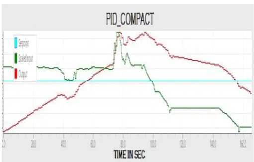
In any industry the control and monitoring of the industrial processes is under the observation of the human operator i.e. at office room and it also consists of the engine room which has number of engines for running the actual industrial processes. In the engine room, data driven control topology is demonstrated only for the control of the temperature of engine room through the speed of ventilation fan via variable frequency drive (VFD). It can be applicable to the various parameters like differential pressure, number of ventilation fan and their relation to each other, etc. The temperature sensor senses the temperature and it is input to the PLC’s PID which will control its output as per the set point specified by the operator through human machine interface (HMI). The output of the PID is given to VFD which will accordingly control speed of ventilation fan. In built PID tuning method used here is Ziegler-Nichols self-oscillation method, this method is a trial and error tuning method based on sustained oscillations. The tuning occurs through ultimate gain Ku with period Tu and by using this two the controller parameters are calculated by Table. 1.The ultimate gain Ku, is the ratio of relay amplitude to amplitude of process oscillations or, more accurately, as shown in Eq. 1-4:
𝑁(𝑎) =4𝑑
𝜋𝑎 (1)
Here d is relay amplitude and a is process output amplitude. The condition for close loop system to produce cycle oscillation is given by
N(a) * G(jω) = -1 (2) Where G(jω) is the transfer function of the plant.
arg G(jω) = - π
𝐾𝑢 = − 1
𝐺(𝑗𝑤) (3) Hence
𝐾𝑢 =4𝑑
𝜋𝑎 (4)
Table. 1: The Formula of Z-N Critical Ratio Fast performance
Controller Kc Ti Td
P 0.5 Ku - -
PI 0.4 Ku 0.8 Tu -
PID 0.6 Ku 0.5 Tu 0.12 Tu
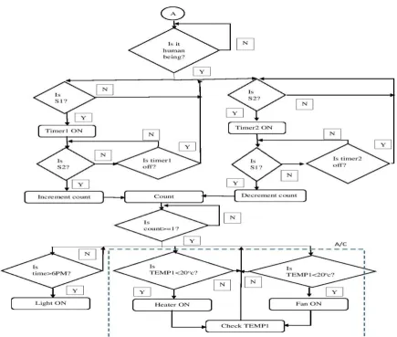
This data driven control topology also consists of office room concept in which LDR sensor at the door and PIR sensor are used to sense and count the number of persons present in the office room and by using this value of count, all the electrical appliances of that office room will be switched ON or OFF as per the specified requirement which will be programmed in PLC program. The algorithm developed for data driven control topology fir an energy efficient management is as shown in flowchart given in Fig.6(a) and Fig. 6(b). In initialization all the data that is present in the counter and the real time clock memory are reset to its default values and start the process from beginning. In the analysis of different parameters through sensors, the temperature sensor output in office room (TEMP1), temperature sensor output in engine room (TEMP2), LDR sensors output and PIR sensor output will be analyzed. Part of flowchart shown in Fig. 6(b) with connector ‘A’ is the office room part of the data driven control topology. Dashed part in the Fig. 6(a) shows process for engine room and in Fig.6(b) shows function of air conditioner in actual industrial processes.
IV. RESULTS
Volume 3, Special Issue 1, ICSTSD 2016
V. CONCLUSION
In this paper, the designed and developed data driven control topology has been demonstrated for an energy efficient management of the industrial process under consideration consisting of engine room and office room of the industrial building. The control algorithm is purely based on real-time process measurements, which are used as feedback signals to
take proper actions by PLC. The algorithm running on PLC is based on data driven control topology and is used to adjust speed of ventilation fan using in-built PID controller of PLC to maintain temperature in engine room. Other part of the algorithm turns the electrical appliances ON/OFF depending upon the presence of human being in office room. So by using this concept of data driven control topology, considerably reduction in the power consumption required for the industrial process is possible as compared to the normal operation of the industrial process.
Acknowledgment
The authors thankful to the Sardar Patel Institute of Technology, India for providing the necessary facilities for carrying out this work.
References
[1] The Hang Li, “A novel design for a comprehensive smart automation system for the office environment”, IEEE Emerging Technology and Factory Automation, pp.1-4, sep.2014.
[2] Sahil Sahni, R.K. Jarial, “Plc based home automation system”, Proceedings of IRF International Conference, Bangalore, Mar. 2014 [3] Sheila Mahapatra, et al, “PLC-Based Home Automation System”,
International Journal of Innovative Technology and Exploring Engineering (IJITEE), vol-4, no.5, oct.2014.
[4] S,Sasikala, Olivia Ramya Chitranjan, K.Muthulakshmi, “Implementation of home automation safety control using PLC”, Middle east journal of scientific research, pp.-492-501, 2014.
[5] Spyridon V. Giannoutsos, “A Data-Driven Process Control Topology for Energy Efficiency Optimization of Fan Operation in E/R Ventilation System of Marine Vessels”, IEEE Industry Applications Society Annual Meeting, pp.1-10, oct.2014.
[6] Yuvraj Agarwal, “Occupancy-Driven Energy Management for Smart Building Automation”. Proceedings of the 2nd ACM workshop on Embedded Sensing Systems for Energy-Efficiency in Building, pp.1-6, nov.2010.
[7] Dai Sheng-wei, Wang Xin, Li Yan-lin, Hu Zhen-yu,“The PLC based control system for intelligent garage”, Third International Conference on Intelligent System Design and Engineering Applications, pp. 1483-1486, 2013.
[8] K.G. Bante, S. G. Ternekar, D.R. Tutakane “Industrial power electronics and PLC system solution for enhancing the performance of AC/DC drive for specific application”, International Conference on Emerging Trends in Engineering and Technology, 2013.
[9] D. Sowmiya,, “Monitoring and Control of a PLC Based VFD Fed Three Phase Induction Motor for Powder Compacting Press Machine”, International Conference on Intelligent System and Control, IEEE, pp.90-92, jan.2013.
[10] Pooja Dhandare, Pooja Maharir,A. A. Shinde “Synchronization of ESRs with Main Line using PLC and SCADA”, International Journal of Emerging Technology and Adv engineering, Apr. 2014
Fig. 3 HMI screen showing real time clock
Fig. 4 HMI screen showing count and PID set point
Fig. 6(a) Flowchart of data driven control topology