Printed in The Islamic Republic of Iran, 2009 © Shiraz University
A SIMPLIFIED DROOP METHOD IMPLEMENTATION IN PARALLEL UPS
INVERTERS WITH PROPORTIONAL-RESONANT CONTROLLER*
A. HASANZADEH AND H. MOKHTARI**
Electrical Eng. Dept., Sharif University of Technology, Tehran, Iran Email: [email protected]
Abstract– In this paper, a simpler implementation of the well-known droop method for the control of parallel
Uninterruptible Power Supply (UPS) systems is presented. In this method, in the power-sharing control scheme, the output current is calculated by software without the need for a current sensor, resulting in a simpler and cheaper structure. By doing so, the number of feedback sensors is reduced from three to two. The paralleling strategy uses the droop method in which the control strategy is based on the drop in the inverter output frequency and amplitude. The application of Proportional-Resonant (PR) controllers is also extended to parallel inverter and its superior performance over the well-known Proportional-Integral-Derivative (PID) controller is shown. To show the performance of the proposed system, a system of two-parallel connected UPS is simulated, and two types of linear and non-linear loads are considered. The non-linear load is compliant with the IEC 62040-3 standard for class I UPS. The results show that the reduction of sensors results in no error, and the control system performance is quite satisfactory. To verify the proposed concept, a two-625VA UPS system is implemented. Several tests on both linear and non-linear loads are performed and the results, which are in good agreement with those of the simulations, are provided. The results indicate that the proposed parallel inverter control structure provides a better system in terms of performance parameters.
Keywords– Uninterruptible power supply (UPS), droop control method, proportional-resonant (PR) controller
1. INTRODUCTION
Parallel UPS systems have become a desirable solution, especially in places where the amount of voltage-sensitive loads is high. On the one hand, in a parallel UPS system each UPS must be able to operate independently in order to achieve true redundancies which include better stability and robustness [1-2]. On the other hand, when working in parallel, precise power sharing among the parallel-connected UPSs must be obtained. This is achieved by different methods with tight adjustments of the output voltage frequency and amplitude [2-5]. One of these power sharing techniques in UPS systems is based on the droop method [6-7]. This method is derived from a power system theory in which the frequency of a generator drops as its load increases.
In this paper, two main issues are discussed. One is simplifying the hardware implementation of droop control loop of parallel connected UPS inverters. The other one is applying a PR controller to a parallel UPS inverter system main control loop for better output regulation and lower total harmonic distortion (THD).
For output regulation of UPS inverters, different linear controller schemes such as PID [89], H -based [10-11] or deadbeat controllers [12-13] are proposed. However, these controllers are unable to yield satisfactory results in the case of disturbances [14]. To overcome these limitations, several non-linear control techniques have been offered. Sliding mode is one of the methods which offers robustness against external disturbances [15]. But in this method, the switching frequency varies over a wide range, making
∗Received by the editors May 24, 2008; Accepted April 12, 2009. ∗∗
the design of the inverter filter elements difficult. The method may also suffer from chattering problem as well [16-18]. Two basic approaches are proposed in [16-18] to obtain a constant switching frequency. These methods use variable hystersis bands or add an adequate constant frequency signal. However, these techniques can suffer from stability problems, sluggish transient performance and control logic implementation complexity. In earlier literature some adaptive control methods are presented, however, implementing these methods is complex due to the complicated mathematics in their control logic [19-20]. Resonant controllers or PR controllers have been proposed to solve the aforementioned problems [21-23].
In this paper, an application of a PR controller in the main control loop is presented. The advantages of the proposed technique can be summarized as: constant switching frequency, robustness against input/output changes, fast dynamic response, simple control logic implementation and low output voltage THD.
This paper also offers a simpler hardware by reducing the number of feedback signals which are normally three. These three signals include the two signals used in stand-alone UPS inverter control, the output filter current and output voltage. The third signal is the output current of which, along with the common output voltage, is used for parallel operation of UPSs. In this work, the output current feedback used in the droop method is implemented in a software routine. Therefore, the proposed system offers less complexity and more noise immunity as compared to existing systems.
The paper is organized as follows: in Section 2, a review of the droop method is presented. In Section 3, the design of the output-voltage regulation loop of a single-phase inverter is derived using feedback linearization techniques. Section 4 presents a software-implemented output current feedback in the power-sharing controller. Section 5 explains the controller implementation, and sections 6 and 7 provide simulation and experimental results with linear and non-linear loads using a two-625VA-UPS inverter system.
2. REVIEW OF THE DROOP METHOD
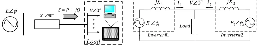
Figure 1 shows an equivalent circuit of an inverter connected to a load bus. The complex power delivered to the load is:
jQ
P
S
=
+
(1)where the active and reactive powers are:
φ sin
X EV
P= (2)
X V EV
Q
2
cos −
= φ (3)
Figure 2 shows two inverters connected to a common load with an inductive output impedance.
φ ∠
E S=P+jQ V∠0o o
X∠90
Load
1 1∠φ
E E2∠φ2
o
V∠0 1
i
Load 1
jX jX2
1 #
Inverter Inverter#2
2
i
Fig. 1. Equivalent circuit of an inverter connected to a load bus
The droop concept is taken from power system theory, in which load sharing among different generators is performed based on the P−
ω
droop characteristics. This concept has been extended to parallel UPSs. In order to have control over both active and reactive powers as shown in Fig. 3, the following droop schemes are defined [6-7]:mP
−
=
ω
*ω
(4)nQ E
E= *− (5)
The higher the droop coefficients, the better the droop sharing, but the worse the voltage regulation. Therefore, a trade-off is to be made between these two milestones [6] and [24].
∗ E E E ∆ Q nQ E E= ∗−
∗ ω ω ω ∆ P N
P QN
mP − = ∗
ω ω
Fig. 3. Static droop characteristic ω−P and E−Q
3. DESIGN OF THE OUTPUT-VOLTAGE REGULATION LOOP
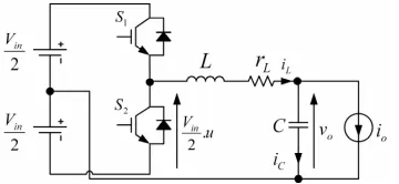
The objective of this section is to derive an inner control loop that provides good reference tracking and regulates the inverter output voltage. Input–output linearization control techniques are used to derive this control loop. Figure 4 shows the power circuit of a single-phase inverter. It includes an IGBT half-bridge configuration and an LC filter. The equivalent series resistance
Fig. 4. Power circuit of the single-phase UPS inverter
(ESR) of the filter capacitor is not considered because of its negligible effect on the system performance [9]. The following differential equations can be written from the power circuit shown in Fig. 4:
L L o in L i r v u V dt di
L = − −
2 (6)
o L c o i i i dt
dv
C = = − (7)
where u is the control variable which can be 1, 0, or –1 depending on the state of the switches S1 and S2. According to non-linear control and feedback linearization theory [25], from (6) the open-loop averaged output-voltage dynamics can be derived as:
u V i r v dt i d L in L L o L 2 = +
+ (8)
where means the average value over one switching cycle.
In order to linearize and achieve good reference tracking of the output voltage, the following controller expression from the block diagram in Fig. 5 is proposed:
{
}
ref o L PCPV
in u k L G s v v i k
V ) ) )( ) ( (( 2 1 − > < − +
where L−1 stands for the inverse Laplace transform.
In this controller, the voltage controller consists of a proportional block plus a PR controller, i.e.
) (s
G , which offers better performance than that of a conventional PID controller [21-23], and theoretically, has infinite gain at a frequency called the resonant frequency. Therefore:
2 0 2 2 Re 2 ) (
ω
ω
ω
ω
+ + + + = − cs cs cs s P s s s k sG (10)
where S is the Laplace operator.
To further improve the voltage controller performance, the location of the zero in the z-transform of the PR controller is shifted by a bit towards the origin. This reduces the steady-state error of the output voltage, since the zero acts like an integrator operand in the controller. This correction results in a better output voltage regulation and lower THD and reduces the steady state error as well.
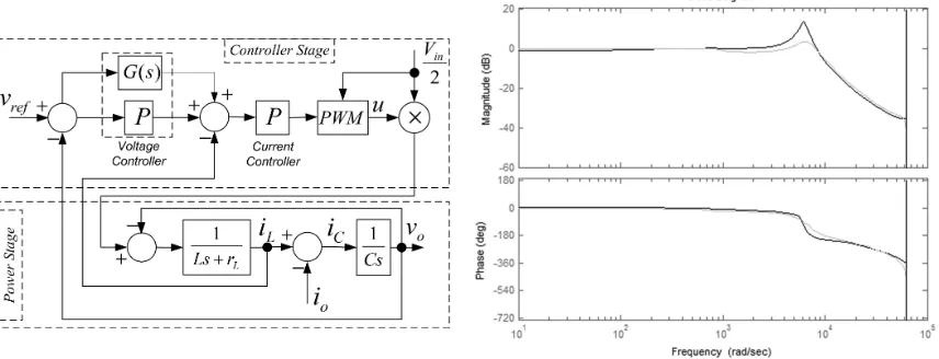
Figure 6 compares Bode plots of the closed-loop transfer function of the overall system of the PR controller with that of a conventional PID controller using the design parameters listed in Tables 1 and 2.
Fig. 5. Block diagram scheme of the single phase inverter output-voltage controller with
power circuit stage
Fig. 6. Bode diagrams of the closed-loop transfer function of the system: with the conventional
PID (light trace) and with the PR controller (dark trace)
Table 1. Parameters of the UPS inverter power stages
Item Value
Filter inductor # 1 (L1) 1.187 mH Filter inductor # 2 (L2) 1.263 mH Parasitic resistor # 1 (rL1) 0.15 Ω Parasitic resistor # 2 (rL2) 0.2 Ω
Filter capacitor # 1 (C1) 39.6 µF Filter capacitor # 2 (C2) 40.3 µF Common load inductor (LL) 18.7 mH
Common load resistor (RL) 7.9 Ω
Bus voltage (Vin) 380 V
Switching frequency (fS) 20 kHz Output frequency (fO) 50 Hz
Output voltage (VO) 110 Vrms
Table 2. Parameters of the UPS inverter control stages
Item Value
PR &PID current controller proportional gain (KPC)
0.05 --
PR &PID voltage controller proportional
gain (KPV) 0.2 --
PR voltage controller resonant gain (K
P-Res)
1000 1/s
PID voltage controller integrator gain
(KP-I) 1000 1/s
PID voltage controller derivative gain (KP-D)
10 s
Voltage controller cut-off frequency (ωcs)
2 ×20 rad/s
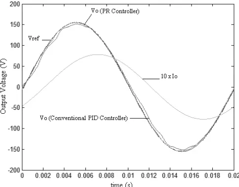
Figure 7 shows the output current, output voltage reference, and output voltage for both cases. By using the PR controller, the output voltage perfectly follows the reference, while with the conventional PID, there is a lag in phase and error on the steady-state amplitude.
Fig. 7. Comparison of output voltage waveforms using a conventional PID and the PR controller
4. HARDWARE SIMPLIFICATION: SOFTWARE-IMPLEMENTED OUTPUT CURRENT FEEDBACK
This section describes the feedback structure of the proposed control method. As mentioned earlier, the number of feedback sensors is reduced from three to two by calculating the output current using a software block. From the conventional droop scheme, the active and reactive powers are described in discrete format as follows:
] [ ] [ ]
[k v k i k
P = o o (11)
] 4 [ ] [ ] [
S o o
T T k i k v k
Q =− − (12)
) 4 ( TS
T is an integer sample number to calculate the o
90
− phase-shift delay in the output current needed for the reactive power calculation. The sample time TS is selected such that the term T (4TS)becomes an integer number.
Then, the active power Pn and the reactive power Qnare passed through the following low-pass filter:
S cfT cf LP
e z
z z
H ( ) ω−ω . −
= (13)
where the filter cut-off frequency
ω
cf is set to one decade below the line frequency.The droop coefficients m and n are then put into Eqs. (4) and (5). Having known the angular frequency deviation, the phase difference between the inverter and load bus can be found using Eq. (14):
t dt d
∆ ∆ ≈ =
−ω φ φ
ω*
(14)
) sin(
)
( *−∆
ω
* −∆φ
= E E t
vref (15)
Table 3 shows the required parameters for the reference generation of the droop controller loop. This reference signal is updated at every line frequency period or a factor of switching frequency. Using Fig. 4 one can write:
] [ ] [ ]
[k i k i k io = L − C
(16)
Substituting (16) into (11) and (12) yields:
]) [ ] [ ]( [ ]
[k v k i k i k
P = o L − C (17)
]) 4 [ ] 4 [ ]( [ ] [ S C S L o T T k i T T k i k v k
Q =− − − − (18)
The second term on the right side of Eq. (17) has zero active power over a line frequency period. Also, from the inverter output voltage, which is equal to the output capacitor voltage, the capacitor current can be written as:
dt dv C
i o
C= .
(19)
Since the high frequency components of the capacitor current are attenuated by the low-pass filter defined by (13), this current can be approximated by:
o o C jC V
I = ω (20) or:
] [ ]
4
[ C v k
T T k
i C o
S
C − = ω (21)
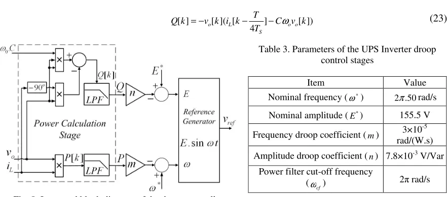
Finally, substituting iC[k] into Eq. (17) and (18) results in Eq. (22) and (23). This converts the conventional droop method into a new structure of droop implementation shown in Fig. 8.
] [ ] [ ]
[k v k i k
P = o ⋅ L (22)
]) [ ] 4 [ ]( [ ]
[ C v k
T T k i k v k
Q o o
S L
o − − ω
−
= (23)
Table 3. Parameters of the UPS Inverter droop control stages
Item Value
Nominal frequency ( *
ω ) 2π.50rad/s
Nominal amplitude ( *
E ) 155.5 V
Frequency droop coefficient (m) 3×10 -5
rad/(W.s)
Amplitude droop coefficient (n) 7.8×10⁻³ V/Var
Power filter cut-off frequency
(ωcf) 2 rad/s
Fig. 8. Improved block diagram of the droop controller
current sensors is also possible, even if more complex droop techniques as described in [6-7] are used.
5. CONTROLLER IMPLEMENTATION
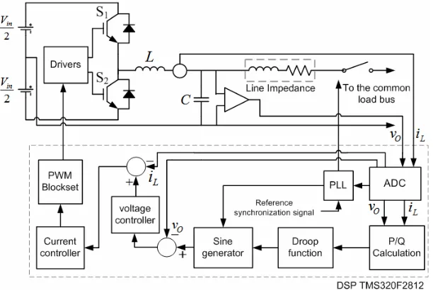
Figure 9 shows a block diagram of the power-sharing controller. The controller also includes a Phase-Locked-Loop (PLL) block in order to synchronize the inverter output with the common bus at the startup. When this occurs, the UPS inverter is connected to the common bus and the droop-based control is initiated. Also, the line impedance plays an important role for the output current difference when load sharing occurs.
Fig. 9. Block diagram of the power sharing controller
The control logic includes the power-sharing droop controller, reference generators, low-pass filters and voltage/current controllers which are implemented by means of a TMS320F2812, 32-bit fixed-point 150-MHz Digital Signal Processor (DSP) from Texas Instruments. The voltage and current sampling frequency is rated at 20 kHz.
The control law can be applied by comparing the output signal of the current controller with a triangular waveform scaled by the input voltage magnitude in a unipolar or bipolar Pulse-Width- Modulated (PWM) approach. This section is also implemented by a software routine with the help of the DSP PWM block. This results in a PWM generator that decouples the output voltage dynamics from input voltage variations.
6. SIMULATION RESULTS
The proposed controller is simulated by using Matlab/Simulink/SimPower Systems Blockset for a two-parallel-inverter system sharing a load in order to show the feasibility of the proposed optimized droop and output voltage controller. The droop, control and power stages parameters are given in Tables 1, 2 and 3 respectively.
Table 4. Simulation results of the parallel UPS inverters with linear load
With droop controller
Item Without droop controller with output current sensor without output current sensor Output RMS
current UPS inverter # 1 (IO1)
5.9 A 5.64 A 5.64 A
Output RMS current UPS inverter # 2 (IO2)
5.18 A 5.26 A 5.28 A
No load output RMS voltage
(VONL)
112.2 V 112.2 V 112.2 V
Full load output RMS voltage
(VOFL)
108.2 V 107 V 107 V
Output voltage THD (THDVo)
1.2-1.5 % 1.4-2 %
Sharing current (ISharing)
0.736 A 0.45 A 0.43 A
Table 5. Simulation results of the parallel UPS inverters with non-linear load
With droop controller
Item Without droop controller with output current sensor without output current sensor Output RMS
current UPS inverter # 1 (IO1)
5.98 A 5.9 A 5.9 A
Output RMS current UPS inverter# 2 (IO2)
5.33 A 5.315 A 5.32 A
No load output RMS voltage
(VONL)
112.2 V 112.2 V 112.2 V
Full load output RMS voltage
(VOFL)
109.1 V 108.7 V 108.7 V
Output voltage THD (THDVo)
1.2-1.5 % 4.6-4.9 %
Sharing current (ISharing)
0.699 A 0.62 A 0.61 A
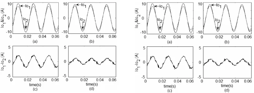
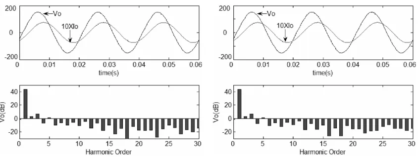
The results are also summarized through Figs. 10 to 12 and 13 to 15 for both linear and non-linear loads, respectively. The non-linear load is compliant with the IEC 62040-3 standard for class I UPS. Figure 10 depicts the steady state output current of a two-parallel-inverter system with and without the droop controller. In this figure, the droop controller performance is shown with the output current sensor (left side) and without the output current sensor (right side). This figure shows that the proposed droop scheme reduces the current differences from 0.736A to 0.43A-0.45A (approximately 40%). From this figure, it can be seen that the reduction in the number of sensors has caused no error in the performance of the system operation. Figure 11 demonstrates the transient behavior of the load sharing with and without the output current sensor. In this figure, no-load to full-load changes at 20 ms and the droop controller is activated at 180 ms. Figure 12 depicts the output voltage, its spectrum and the output current with and without the output current sensor, respectively.
Fig. 10. Steady state output current waveforms and their differences -with output current sensor (Left) -without output current sensor (Right): a) and c) without the
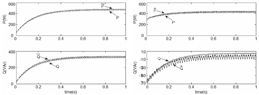
Figures 13 to 15 show the same results when the system supplies a non-linear load. Figure 16 presents the output active and reactive powers for both linear and non-linear loads with the proposed scheme. Frequency and amplitude deviations for the two types of loads are shown in Fig. 17.
Fig. 11. Transient output current waveforms -with output current sensor (Left) -without output current sensor (Right): (0-20ms) no load and without droop controller, (20ms-180ms) with load and without
droop controller, and (180ms-500ms) with load and droop controller; linear load
Fig. 12. Output voltage with its spectrum and output current waveforms -with output current sensor (Left) -without output current sensor (Right); linear load
Fig. 13. Steady state output current waveforms and their differences -with output current sensor (Left) – without output current sensor (Right): a) and c) without the droop controller, b) and
Fig. 14. Transient output current waveforms -with output current sensor (Left) -without output current sensor (Right): (0-20ms) no load and without droop controller, (20ms-180ms)
with load and without droop controller, and (180ms-500ms) with load and droop controller; non-linear load
Fig. 15. Output voltage with its spectrum and output current waveforms -with output current sensor (Left) -without output current sensor (Right); non-linear load
Fig. 16. Waveforms of active and reactive power: without the output current sensor (P~,Q~ ) and with the output current
Fig. 17. Frequency and amplitude deviation: a) and b) without the droop controller, c) and d), with the droop controller in supplying a linear load (Left) and a non-linear load (Right) for two UPS inverters 1&2
7. EXPERIMENTAL RESULTS
Two 625VA UPS inverters are built and tested to experimentally confirm the performance of the proposed system. Each inverter consists of a single-phase half-bridge using IGBTs with a switching frequency of 20 kHz and an L−C output filter with parameters listed in Table 1.
Experimental tests are performed by supplying a linear load with a power factor of 0.8 and a non-linear load compliant with the IEC 62040-3 standard for class I UPS. Figure 18 depicts the two UPS inverter output currents and their differences without the droop controller for the linear and non-linear loads, respectively. Figure 19 shows the same results with the droop controller functional and with the output current sensor. Figure 20 shows the same results with the droop controller and without the output current sensor. The output voltage and current of one inverter module is shown in Fig. 21 for the two different types of linear and non-linear loads. In this figure, the quality of the output voltage is illustrated by its spectrum. The measured total harmonic distortion (THD) of the load voltage for linear and non-linear loads is less than 2% and 5%, respectively. These specifications are compliant with the IEC 61000-2-4 standard, which requires a THD less than 5% for class I UPSs.
Fig. 18. Experimental results showing the two UPS inverter output currents (Up), and their difference without the droop controller - linear load (Left) and non-linear load (Right) (Ch.1, Ch.2: Current waveforms,
Fig. 19. Experimental results showing the two UPS inverter output currents (Up), and their difference with the droop controller - linear load (Left) and non-linear load (Right) (Ch.1,Ch.2: Current waveforms,
X axis: 5ms/div, Y axis: 7A/div Ch.M (MATH=Ch.1-Ch.2): Current waveforms difference, X axis: 5ms/div, Y axis: 7A/div)
Fig. 20. Experimental results showing the two UPS inverter output currents (Up), and their difference with the droop controller and no output current sensor - linear load (Left) and non-linear load (Right) (Ch.1,
Ch.2: Current waveforms, X axis: 5ms/div, Y axis: 7A/div Ch.M (MATH=Ch.1-Ch.2): Current waveforms difference, X axis: 5ms/div, Y axis: 7A/div)
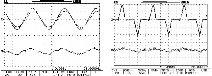
Fig. 21. Experimental result showing the load voltage and its frequency spectrum and load current -linear load (Left) and non-linear load (Right) (Ch.1: Voltage waveforms, Y axis: 100V/div, Ch.2: Current
Fig. 22. Experimental result showing the two UPS inverter output currents connected to each other and then sudden connection to a linear load (Left) and a non-linear load (Right) (Ch-1,Ch-2: Current
waveforms, X axis: 5ms/div, Y axis: 7A/div(Left) Y axis: 17.5A/div(Right))
The dynamic performance of the parallel system in response to a sudden load charge is also experimentally evaluated. Figure 22 shows the transient response of output currents for both inverters with linear and non-linear loads. Initially, the UPS modules operate in parallel without a load, but, due to measurement errors, a small reactive circulating current appears between the modules. The excellent dynamic behavior of the system can be seen from this figure. The measurements of the two modules are also summarized in Tables 6 and 7. These tables confirm the simulation results and show that the new proposed parallel inverter system achieves better performance than the conventional one.
Table 6. Experimental Results of the Parallel UPS Inverters with Linear Load
with droop controller
Item without droop controller with output current sensor without output current sensor Output RMS
current UPS inverter # 1 (IO1)
6 A 5.7 A 5.7 A
Output RMS current UPS inverter # 2 (IO2)
5.2 A 5.4 A 5.4 A
No load output RMS voltage
(VONL)
112 V 112 V 112 V
Full load output RMS voltage
(VOFL)
108 V 106.8 V 106.8 V
Output voltage THD (THDVo)
1.2-1.7 % 1.5-2 %
Table 7. Experimental Results of the Parallel UPS Inverters with non-linear Load
with droop controller
Item Without droop controller with output current sensor without output current sensor Output RMS
current UPS inverter # 1 (IO1)
6.1 A 6 A 6 A
Output RMS current UPS inverter # 2 (IO2)
5.3 A 5.4 A 5.4 A
No load output RMS voltage
(VONL)
112 V 112 V 112 V
Full load output RMS voltage
(VOFL)
110 V 109.3 V 109.3 V
Output voltage THD (THDVo)
1.2-1.7 % 4.5-5 %
8. CONCLUSION
presents an application of the PR controller in parallel UPS inverters. A wireless controller is proposed by designing three nested loops. The inner current control loop achieves good dynamic performance of the UPS inverter output current. The intermediate voltage control loop implemented with an optimized PR controller provides output voltage shaping. These loops are implemented by using feedback linearization techniques giving a non-linear controller which is able to provide good output tracking.
The outer droop control loop, which is simplified and optimized by removing the output feedback current, is used to achieve excellent power balance when sharing loads. The complete controller is tested with the objective of sharing active and reactive power without frequency or amplitude steady-state deviations.
Simulation and experimental results are presented for linear and non-linear loads under steady state and transient conditions to validate the proposed control approach and its good load sharing capability. The results show that the proposed parallel inverter system offers better output voltage regulation, lower output voltage THD, more desired dynamic performance and a more precise sharing scheme than the conventional one.
NOMENCLATURE
P
active powerL
r inverter output filter inductor resistor
Q
reactive powero
v inverter output voltage
E inverter output voltage amplitude
o
i inverter output current
V common load voltage amplitude
L
i inverter output filter inductor
φ
power angleC
i inverter output filter capacitor
X output reactance of the inverter
ref
v output voltage reference *
ω
output voltage frequencyω
0 PR controller resonant frequency*
E amplitude at no load
ω
cs PR controller cut-off frequencym droop frequency coefficients
T
period of the fundamental frequencyn droop amplitude coefficients
S
T period of the sampling frequency
L inverter output filter inductor k sample number
C inverter output filter capacitor
cf
ω
droop low pass filter cut-off frequencyREFERENCES
1. De Para, U., Baert, D. & Huyken, H. (1998). Analysis of the degree of reliability of a redundant modular inverter structure. The Twentieth International Telecommunications Energy Conference (INTELEC), pp. 543-548.
2. Emadi, A., Nasiri, A. & Bekiarov, S. B. (2004). Uninterruptible power supplies and active filters. Boca Raton:
CRC Press, ISBN: 0-8493-3035-1.
3. Xue, Y., Chang, L., Kjaer, S. B, Bordonau, J. & Shimizu, T. (2005). Topologies of single-phase inverters for small distributed power generators: an overview. IEEE Trans. on Power Electronics, Vol. 19, No.5, pp. 1305 - 1314.
4. Cheng, Y. J. & Sng, E. K. K. (2006). A novel communication strategy for decentralized control of paralleled multi-inverter systems. IEEE Trans on Power Electronics, Vol. 21, No. 1, pp. 148 - 156.
6. Guerrero, J. M., Matas, J., de Vicuña, L. G., Castilla, M. & Miret, J. (2006). Wireless-controller Strategy for
parallel operation of distributed-generation inverters. IEEE Trans. on Industrial Electronics, Vol. 53, No. 5, pp.
1461-1470.
7. Guerrero, J. M., Matas, J., de Vicuña, L. G., Castilla, M. & Miret, J. (2007) Decentralized control for parallel
operation of distributed-generation inverters using resistive output impedance. IEEE Trans. on Industrial
Electronics, Vol. 54, No. 2, pp. 994-1004.
8. Abdel-Rahim, N. M. & Quaicoe, J. E. (1996). Analysis and design of a multiple feedback loop control strategy
for single-Phase voltage source UPS inverters. IEEE Trans. on Power Electronics, Vol. 11, No. 4, pp. 532-541.
9. Ryan, M. J., Brumsickle, W. E. & Lorenz, R. D. (1997). Control topology options for single-phase UPS
inverters. IEEE Trans. on Industry Applications, Vol. 33, No. 2, pp. 493-501.
10. Lee, T. S., Chiang, S. J. & Chang, J. M. (2001). H
∞
loop-shaping controller designs for the single-phase UPSinverters. IEEE Trans. on Power Electronics, Vol. 16, No. 4, pp. 473-481.
11. Willmann, G., Coutinho, D. F., Pereira, L. F. A. & Libano, F. B. (2007). Multiple-loop H-infinity control design
for uninterruptible power supplies. IEEE Trans. on Industrial Electronics, Vol. 54, No. 3, pp. 1591-1602.
12. Mattavelli, P. (2005) An improved deadbeat control for UPS using disturbance observers. IEEE Trans on
Industrial Electronics, Vol. 52, No. 1, pp. 206-212.
13. Mohamed, I., Abdel-Rady, Y. & El-Saadany, E. F. (2007). An improved deadbeat current control scheme with a
novel adaptive self-tuning load model for a three-phase PWM voltage-source inverter. IEEE Trans. on Industrial
Electronics, Vol. 54, No. 2, pp. 747-759.
14. Marwali, M. N. & Keyhani, A. (2004). Control of distributed generation systems—Part I: voltages and currents
control. IEEE Trans. on Power Electronics, Vol. 18, No. 1, pp. 344-355.
15. Wai, R. J. & Lee, M. C. (2004). Robust sliding-mode control for nonlinear flexible arm using neural network.
Iranian Journal of Science & Technology, Transaction B. Engineering, Vol. 28, No. B3, pp. 337-350.
16. Pinheiro, H., Martins, A. S. & Pinhero, J. R. (1994). A sliding mode controller in single phase UPS inverters.
International Conference on Industrial Electronics, Control and Instrumentation, IECON, pp. 394-398.
17. Ramos, R. R., Biel, D., Fossas, E. & Guinjoan, F. (2003). A fixed-frequency quasi-sliding control algorithm:
application to power inverters design by means of FPGA implementation. IEEE Trans. on Power Electronics,
Vol. 19, No. 6, pp. 1541-1550.
18. Ramos, R. R., Biel, D., Fossas, E. & Guinjoan, F. (2008). Interleaving quasi-sliding-mode control of
parallel-connected buck-based inverters. IEEE Trans. on Power Electronics, Vol. 55, No. 11, pp. 3865 - 3873.
19. Escobar, G., Valdez, A. A., Leyva-Ramos, J. & Mattavelli, P. (2007). Repetitive-based controller for a UPS
inverter to compensate unbalance and harmonic distortion. IEEE Trans. on Industrial Electronics, Vol. 54, No.
1, pp. 504-510.
20. Escobar, G., Mattavelli, P., Stankovic, A. M., Valdez, A. A. & Leyva-Ramos, J. (2007). An adaptive control for
UPS to compensate unbalance and harmonic distortion using a combined capacitor/load current sensing. IEEE
Trans. on Industrial Electronics, Vol. 54, No. 2, pp. 839-847.
21. Teodorescu, R. & Blaabjerg, F. (2004). A new control structure for grid-connected LCL PV inverters with zero
steady state error and selective harmonic compensation. Nineteenth Annual IEEE Applied Power Electronics
Conference and Exposition, APEC '04, pp. 580-586.
22. Asiminoaei, L., Teodorescu, R. & Blaabjerg, F. (2006). Multiple harmonics control for three-phase grid
converter systems with the use of PI-RES current controller in a rotating frame. IEEE Trans. on Power
23. Liserre, M., Pigazo, A., Dell’Aquila, A. & Moreno, V. M. (2006). An anti-islanding method for single-phase
inverters based on a grid voltage sensorless control. IEEE Trans. on Industrial Electronics, Vol. 53, No. 5, pp.
1418-1426.
24. Coelho E. A. A., Cortizo, P. C. & Garcia, P. F. D. (2002). Small-signal stability for parallel-connected inverters
in stand-alone AC supply systems. IEEE Trans. on Industry Applications, Vol. 38, No. 2, pp. 533–542.