Design of a Controller with ANFIS Architecture Attendant
Learning Ability for SSSC-Based Damping Controller
Applied in Single Machine Infinite Bus System
A. Khoshsaadat*, M. R. Mosavi**(C.A), J. S. Moghani* and A. Khoshooei*
Abstract: Static Synchronous Series Compensator (SSSC) is a series compensating
Flexible AC Transmission System (FACTS) controller for maintaining to the power flow control on a transmission line by injecting a voltage in quadrature with the line current and in series mode with the transmission line. In this work, an Adaptive Network-based Fuzzy Inference System controller (ANFISC) has been proposed for controlling of the SSSC-based damping system and applied in a Single Machine Infinite Bus (SMIB) power system. For implementation of the learning process of this controller, we use from one approach of the learning ability that named as Forward Signal and Backward Error Back-Propagation (FSBEBP) method for improving of the system efficiency. This artificial intelligence-based control model leads to a controller with adaptive structure and improved correctness of the system, and finally cause to enhancing to the high damping ability and dynamic performance. System implementation is easy and requires 49 fuzzy rules for inference engine of the system. As compared with the other complex neuro-fuzzy systems, this controller has medium number of the fuzzy rules and low number of the layers, but it has high accuracy. In order to demonstrate of the proposed controller ability, it is simulated and its output compared with that of the classic Lead-Lag-based Controller (LLC) and PI controller.
Keywords: ANFISC, Inference, Learning, LLC, Rules, SMIB, SSSC, Transmission Line.
1 Introduction1
One of the highlight advances in the power electronics application in the power systems is use of the Flexible Alternating Current Transmission System (FACTS) devices. Many of the FACTS devices, such as Thyristor Controlled Series Compensator (TCSC), Static Synchronous Series Compensator (SSSC), Static Synchronous Compensator (STATCOM), Static VAR Compensator (SVC) and Unified Power Flow Controller (UPFC) connected in series, shunt or series-shunt configurations, with or without a storage element, have been proposed, simulated and occasionally applied and implemented in the transmission line systems.
Series FACTS devices are the important devices of the FACTS family, which are identified as effective and economical means to diminish the power system oscillation and power flow control of the transmission
Iranian Journal of Electrical & Electronic Engineering 2014. Paper first received 7 July 2013 and in revised form 1 Feb. 2014. * The Authors are with the Department of Electrical Engineering, Amirkabir University of Technology, Tehran, Iran.
** The author is with the Department of Electrical Engineering, Iran University of Science and Technology, Tehran, Iran.
E-mails: [email protected], [email protected], [email protected] and [email protected].
line. SSSC is a series FACTS devices based on Voltage Source Converter (VSC) structure, and has capability to increase or decrease the overall reactive voltage drop across the line, and so controlling the power flow in the transmission line. This device that injects a controllable voltage in quadrature with the line current of a power transmission line is able to rapidly provide both capacitive and inductive impedance compensation freely the line current. Also, a SSSC can be used to improving the damping ability of the low frequency power oscillations. These properties make the SSSC an appropriate selection for the power flow control, power oscillation damping controller and improving transient stability of the transmission line. Only the voltage is controllable in reactive power compensation because the voltage vector forms 90º degrees with the line intensity. In this situation, the series voltage injected can delay or advanced the line current. This means that the SSSC can be uniformly controlled in any value, in the VSC working slot [1-4].
One point of the FACTS devices based on the SSSC is the designing of a controller for achieving to the proper voltage drop across the transmission line. Note that in many other works, the controller of the SSSC is
based on the classic controller such as Lead-Lag Controller (LLC) and Proportional-Integral-Derivative (PID) controller. The coefficients of these types of the controllers need to be adjusted away with various conditions in the system. Adjusting the coefficients of these controllers do using the many classic methods (such as Ziegler-Nichols method) and newer methods (such as Evolutionary Algorithms (EA)) and etc. Noting to the mentioned point, tuning of the coefficients of these controllers is a hard and important problem. In the Refs. [1, 2, 5] using the EA, like the Genetic Algorithm (GA) and Particle Swarm Optimization (PSO), coefficients of the LLC and PID controller are adjusted.
In some categories of these controllers, designers use the Fuzzy Logic (FL) for controlling of the SSSC, but don't use of the Artificial Neural Network (ANN) in a hybrid architecture. About this technique, Ref. [4] uses of this technique.
In this paper using the collation, learning and parallel processing abilities of the NN and inference capability of the FL, the proposed controller is designed. The controller is adaptive with variation in the system conditions, and has proper fuzzy rules for inference engine. Simulation results show that the proposed controller has higher damping ability with lower ripple and shorter settling time in the waveforms of the rotor speed, active power, stator voltage, rotor angle deviation, rotor speed deviation and injected voltage from SSSC to the transmission line toward Ref. [4]. Also result of this controller compare with one LLC that its parameters is mined from Ref. [2], and proof the priority of the controller against LLC.
In this paper, an Adaptive Network-based Fuzzy Inference System Controller (ANFISC), using the NN and FL is used for controlling of SSSC, that used in the Single Machine Infinite Bus (SMIB) system. This controller used of the two parameters (rotor speed deviation and derivative of the rotor speed deviation) as inputs of the controller. The nodes in the hidden layers of the ANFISC perform as membership functions mapping part, and fuzzy inference engine. This controller is constructed from the fuzzy IF-THEN rules, which are based on a simple engineering knowledge concerning the controlled SSSC. To train the proposed controller, one approach of the Error Back Propagation Learning (EBP) method is used with the minimum of the calculation mass. The ability and efficiency of the controller is demonstrated by simulation results in various conditions.
In this scheme, we use of the one five-layer NN-based architecture for implementation of five parts of ANFISC. The architecture of the NN-based system has 2-14-49-49-1 nodes in the five layers, respectively.
This paper is organized as follows. In section 2, NN and FL, and mixture of them as a base of the proposed ANFISC are demonstrated. SMIB model with SSSC is described in section 3. In section 4, ANFISC is designed and in section 5, learning in ANFISC is
described. Finally, results of simulations of the system, in various conditions and its comparison with other controllers, are represented in section 6.
2 Neural Network, Fuzzy Logic and Hybrid Structures
2.1 Neural Network
ANNs are emulation of biological neural systems. These systems are based on the two main elements that named as neuron and weight. Neuron is a calculation core, and weight is a connection between of the two neurons that usually has a measure between 0 and 1. Using of ANNs has their advantages and disadvantages. Advantages are:
- Can be implemented in any application;
- Ability to perform works that a linear system cannot; - When a part of the ANN fails, it can continue working by their parallel nature; and consequently increase the reliability of the system.
- Has learning ability and can be adapted with the conditions, and does not need to be reprogrammed; - Has a high robustness in relation to disturbances;
Another aspect of the ANNs is that there are different architectures, which consequently requires different types of algorithms, but despite to be an apparently complex system, a NN is relatively simple.
Disadvantages are:
- Needs to training for proper operation; - Requires high mass of calculation;
- Has difficulty in determining the optimum architecture.
2.2 Fuzzy Logic
The FL is a mathematical tool for dealing with uncertainty. FL grants a technique to deal with vagueness and information granularity, and consequently provides a mechanism for representing linguistic constructs such as “many”, “few”, “medium”, “high” and “low”. It uses probability theory to explain whether an event is about to happening, and measuring the chance with which a given event is expected to come about. Membership functions, in linear or non-linear forms, with values between 0 and 1 (usually) are used in FL system to deal with the control problems, such as non-linearity, load disturbances and parameters disturbance. FL same as ANN has advantages and disadvantages.
Advantages are:
- Capability to show the uncertainties of the human knowledge with linguistic variables;
- Simple interaction with the designer of the system; - FL can achieve less overshoot and oscillation;
- FL has ability for Simple extension of the base of knowledge;
Disadvantages are:
- Incapable to generalize, i.e., only answers to what is written in its rule-base;
- FL has no robustness against the topological changes; - FL Depends on the existence of an expert to determine the inference logical rules [6-19].
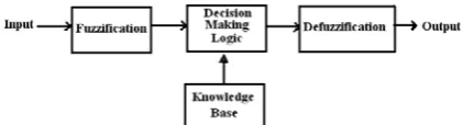
Fig. 1 shows the basic model of a FL system, which is composed of four major components as below:
- Fuzzification Unit: In this part, every input is mapped in the range of the membership functions.
- Knowledge-Based Unit: This part has the rule-base information of system for inference engine.
- Decision Making Logic Unit: this part is generally the product of all incoming signals with inference the fuzzy output from fuzzy inputs. This part perform the fuzzy AND operation.
- Defuzzification Unit: In this part, fuzzy output of the inference engine converts to the crisp signal as the input of the system. Center of Area (COA), Last of Maximum (LOM) and Mean of Maxima (MEOM) methods are some of the defuzzificationmethods.
2.3 Hybrid Systems
Every one of the intelligent methods has special properties that make its proper for particular problems. For example, while ANNs are good at recognizing patterns, but they are not suitable at explaining how they reach their decisions. FL systems, which can reason with imprecise information, are efficient at explaining their decisions, but they cannot automatically acquire the rules that they use them to make those decisions. These limitations have been a central driving force behind the invention of the intelligent hybrid systems. A hybrid intelligent system is one method that combines at least two intelligent techniques. For example, combining ANN with FLS results hybrid neuro-fuzzy system [6-19].
In one way for implementing of the hybrid systems, a NN is used to implement the structure of the fuzzy system. There are several neuro-fuzzy architectures like: Fuzzy Adaptive Learning Control Network (FALCN), Generalized Approximate Reasoning based Intelligence Control (GARIC), Self Constructing Neural Fuzzy Inference Network (SCNFIN), Adaptive Network based Fuzzy Inference System (ANFIS) and Dynamic/Evolving Fuzzy Neural Network (DEFNN) [7].
In this paper, we use of the ANFIS architecture for implementation of the proposed controller. On the other hand, FL control system will implement using the NN. In this method, the sugeno fuzzy model is proposed for generating fuzzy rules from a given input/output dataset. In the part 4, more detailed of this scheme will be represented.
Fig. 1 Block diagram of a FL system.
3 SSSC-based Model of the SMIB Power Systems 3.1 SSSC-Based Infinite Bus Model
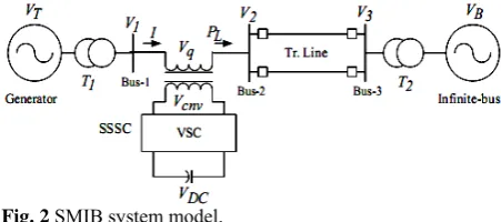
A SMIB system comprises a synchronous generator with the step-up transformer that connected to an infinite-bus. The SSSC is connected to the line in a series structure and finally system followed by a double parallel circuit transmission line. The generator is equipped with Hydraulic Turbine and Governor (HTG) and excitation system. The HTG represents a non-linear hydraulic turbine model, a PID governor system, and a servomotor. The excitation system consists of a voltage regulator and DC exciter, without the exciter’s saturation function [1, 2, 19]. A general model of a SMIB system that equipped with one SSSC is represented in the Fig. 2.
In the Fig. 2, T1 and T2 are the transformers, VT and
VB are the generator and infinite-bus voltages, VDC and
Vcnv are the DC voltage source and output voltage of the
SSSC circuit, and finally V1 and V2 are the bus voltages,
respectively.
The SSSC is characterized by a solid state synchronous VSC that can provide inductive or capacitive compensation and consists of a converter that is connected in series with the transmission line. The output voltage of the SSSC is in quadratic with the line current and is controllable independently of the line current. The compensation level can be controlled dynamically by changing the magnitude and polarity of Vq and finally SSSC can be operated in both capacitive
and inductive modes [1, 2, 20]. A capacitor connected on the DC side of the VSC and acts as a DC voltage source. Instead of the capacitor, the system can use of the fuel cell, battery PV and etc. A DC link with nominal voltage of 40 kV and DC link equivalent capacitance of 375 μF is used in this scheme. For further information about the modeling of SSSC and its control system, please refer Ref. [1].
The phasor solution method is used to study the electromechanical oscillations of power system consisting of large generator and motor. In a transient stability study, the fast oscillation modes that resulting from the interaction of linear R, L, C elements and distributed parameter lines are of no interest. These oscillation modes do not interfere with the slow machine modes and regulator time constants. In the phasor solution method, these fast modes are ignored by replacing the network’s differential equations by a set of algebraic equations. So the state-space model of the network is replaced by a transfer function at the fundamental frequency by relating inputs and outputs. As mentioned above, changing of the injected voltage is performed by means of a VSC. A VSC using IGBT-based PWM inverters is used in this scheme to model the SSSC system. This type of inverter uses PWM technique to generate a sinusoidal waveform from a DC voltage, with a typical chopping frequency of a few kHz. The converter voltage is changed by varying the modulation index of the PWM modulator [1, 2, 20, 21].
3.2 Controllers of the SSSC
The most commonly classic controller that used in the damping controllers based on SSSC structures, are the LLC and PID controller to modulate the SSSC-injected voltage Vq. Despite much advancement, the
LLC structure and PID-based controller remain as an engineer’s selection for many industrial applications because of their simple structure, low cost and high reliability. Despite these advantages, these controllers do have limitations such as inability to adaptation with the variations of the system and have no resistant to the disturbance [1-3]. Therefore nowadays many approach absorbed to use of the other controller such as artificial intelligence-based controllers. These types of controllers compensate many shortages of the classic types such as robustness and adaptation. In this paper, we describe one LLC and also one ANFISC, and finally compare two results of these controllers.
For design of the LLC block, some sub-block should be prepared. Input signal to the system is speed deviation of the rotor and its output is the injected signal to the SSSC for producing the proper voltage from SSSC to the transmission line. The structure of this classic system consists of a delay block, with D symbol, that produces a delay according to the type of input signal, gain block, with the Ks symbol, washout block with the time constant Tw, and two stage lead-lag blocks with the time constants T1s, T2s, T3s and T4s. The two stage lead-lag block provides the appropriate phase-lead characteristics to compensation of the phase lag between input and the output signals. The washout block acts as a high pass filter to allow signals associated with oscillations to pass as it is. For local input signals only the sensor time constants is considered and for remote signals both sensor time constant and the signal transmission delays are included in the delay block. The output of the controller is Vq
signal that represents the injected voltage for the compensation of the power flow control. The block diagram of the LLC is showed in the Fig. 3.
It is worth mentioning that the SSSC is designed to minimize the power system oscillations after a disturbance so as to improve the stability. These oscillations are reflected in the deviation in the generator rotor speed (Δω). In the present study, an integral time absolute error of the speed deviations is taken as the objective function J, expressed as:
1
0 . . t t
t
J ω t dt
=
=
=
∫
Δ (1)In the above equations, |Δω| is the absolute value of the rotor speed deviation and t1 is the time range of the simulation. With the variation of Ks, T1s, T2s, T3s and T4s, J also will be changed. For objective function calculation, the time-domain simulation of the power system model is carried out for the simulation period. It is aimed to minimize this objective function in order to improve the system response in terms of the settling time and overshoot [1-3].
Tuning a controller parameter can be viewed as an optimization problem in multi-modal space as many settings of the controller could be yielding good performance. Traditional method of the tuning doesn’t guarantee optimal parameters and in most cases the tuned parameters needs to improvement through trial and error. In modern heuristic optimization technique-based methods, the tuning process is associated with an optimality concept through the defined objective function and the time-domain simulation. Hence these methods yield optimal parameters and the methods are almost free from the curse of local optimality. Of course, nowadays many new methods based on artificial intelligence help to LLCs for improving of the efficiency. One of these methods is the EA, which applied for detection of the parameters of LLC that are the efficient methods.
In this paper, we use of the one ANFISC, instead of the commonly LLC, that described for implementation of the controller of SSSC-based system, and finally result of two system simulation is compared. Results show that the ANFISC is more adaptive and high efficient to the classic system. For more information about the applied LLC of this work, and how to tuning of its coefficients, please refer to the Ref. [2].
4 Designing of the ANFISC
In this scheme, the controller is represented as a set of fuzzy rules, which accepts the crisp input, and after the mapping to the fuzzy areas, processes the data according to the inference rules, and finally gives the output. These processes are implemented using a five-layer NN, for partaking from parallel processing and learning ability of the NN, neighbor to the inference ability of the FL [22-28].
The ‘IF A AND B, THEN C’ rule-base as a look-up-table is applied to describe the experts knowledge for implementation of the FL system. In Fig. 4, membership functions of inputs variables, which have been used in Fig. 2 SMIB system model.
Fig. 3 Block diagram of the LLC of the SSSC.
this paper, are shown. This membership function is selected as a triangular function. This type of the function has minimum mass of calculation compared with the other membership functions. Other membership functions such as bell-shaped or Gaussian functions also can be applied as beloved function. The basic concept of the FL is use from look-up-table of the two fuzzy inputs, and computes the output from fuzzy operating on them. For implementation of the controller, the rotor speed deviation and derivative of the rotor speed deviation (shown with e and de, respectively) are considered as the two inputs of the FL system. Scale of the every of two fuzzified input is divided to the 7 fuzzy confines. Finally noting to the two inputs and scaling of them, we have output with 49 arrays. In the Fig. 4 membership functions of the input variables, which has been used in this paper, are shown with Seven sets Negative Big (NEB), Negative Medium (NEM), Negative Small (NES), Zero (ZE), Positive Small (POS), Positive Medium (POM), and Positive Big (POB) as the fuzzy measures. Finally, we have a data-base with 49 rules as inference engine that represented in the Table 1. Although we can increase the fuzzy rules, but for avoiding from too mass of calculation, we use the medium numbers of the fuzzy rules in this controller.
Table 1 Fuzzy inference engine of the ANFISC.
POB POM POS ZE NES NEM NEB e de
ZE POS POS POS POM POB POB NEB
NES ZE POS POS POS POM POB NEM
NEM NES ZE ZE ZE POS POM NES
NEM NES ZE ZE ZE POS POM ZE
NEM NES ZE ZE ZE POS POM POS
NEB NEM NES NES POS ZE POS POM
NEB NEB NEM NES NES NES ZE POB
A fuzzy controller represents a non-linear controller; however, it cannot adjust its structure whenever the situation changes. These kinds of controllers also have
the lack the parallelism ability and approximation capability of NN-based controllers. On the other hand, the NNs are very much adaptive to situations by adjusting their weights accordingly.
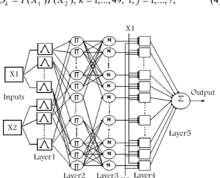
Also the parallel architecture of the NNs enables faster implementation of the control algorithm. To get the advantages of the FL and NNs and to overcome their shortages, it is wised to use the combination of both, which leads to a mixed systems of them [22-24]. Therefore, in the second phase of the scheme, we use of the NN for implementation of the FL system. One of the popular methods for this combination is using of the ANFIS architecture that is one of the members of hybrid neuro-fuzzy systems, as mentioned in the part 2. Fig. 5 shows the structure of the proposed ANFISC, which has been used as a SSSC controller. In this scheme, the rotor speed deviation and also its derivative are used as the inputs of the NN-based system. As shown in Fig. 5, architecture of the NN has five layers as follow:
Layer 1: Each node in this layer generates a
membership grade of a linguistic label. In real, this layer confines the area of each crisp input to one fuzzy limitation. The membership relation between the input and output of each node in this layer can be expressed as below:
1 ( 1); 1, 2;and 1, 2,...,14;
j i
O =T X i = j = (2) where j is the number of the neurons in this layer and i is the number of the inputs (that ANFISC has two inputs). For triangular membership function μ is given by:
;
( ) max[min( , ), 0]
T x x a c x
b a c b
− −
=
− − (3)
where a, b and c are the parameter of the membership function, and governing the triangular membership function accordingly. These parameters have been named premise parameters of the ANFISC.
Layer 2: Each node in this layer has an output that
known as a ''firing strength'' of each rule of FL system via fuzzy multiplication principle:
2 2 2
1 2
( ) ( ); 1,..., 49; , 1,...,7; k
O =T X T X k= i j= (4)
Fig. 4 Membership functions for the rotor speed deviation and derivative of the rotor speed deviation, as two input of the ANFISC.
Fig. 5 Structure of the ANFISC based on the NN architecture.
Layer 3: In this layer, the ratio of the strength of each rules to the sum of the all rules strengths has been calculated as below:
3
49
1
; , 1, 2,..., 49; k
i k k
k k
W
O W i k
W = = = = = ⎛ ⎞ ⎜ ⎟ ⎝
∑
⎠ (5)The name of the output of this layer is the normalized firing strength.
Layer 4: In this layer, every node has a node
function as below: 4
1 2
( ), 1,..., 49;
i k k k k k k
O =W f =W p X +q X +r k= (6)
where pi, qi and ri are called linear parameters of the output sugeno type fuzzy rules.
Layer 5: Finally, in this layer, one neuron exists that
compute the overall summation of the incoming signals: 49 5 1 1 k k k k
O = W f
=
=
∑
(7)For our controller this node is single because controller has one output.
5 Learning Process in ANFISC
A sugeno form of the rules for ANFIS architecture is as *IF Xi is Aiand Yiis Bi, THEN fk=pkXi+qkYi+rk*.
There are many methods for updating of the ANFIS parameters. One of the learning algorithm for ANFIS is based on the hybrid learning algorithm where premise and consequent parameters are to be updated after each data presented into the algorithm, known as Forward Signal and Backward Error Back-Propagation (FSBEBP). For the training of the network, there is a forward path and a backward path. In the forward path, the input vector propagates through the network layer by layer. In the backward path, the error is sent back through the network in a similar manner to EBP. Indeed, in the backward pass, errors calculated will be passed back and the premise parameters will be adjusted using the gradient decent method.
For this ANFISC, we now need to calculate the partial derivatives of the error function with respect to the parameters of the fuzzy system, which needs to be tuned. On the other hand, for every parameter gi, we
have to calculate:
( )
k k k k
k k
i k i i
E E O O
O y
g η O g η g
∂ = ∂ ∂ = − ∂
∂ ∂ ∂ ∂ (8)
where, η is the learning rate of the NN-based system, gi is the consequence parameter and Oi is the output of the i-th layer. That Ek is the cost function of the error and usually can be writing as:
2
1( )
2
k k k
E = d −O (9)
That dkis the desired response of the k-th layer, and Ok is the output of the k-th layer.The error rate for the consequence parameters can be calculated using the chain law as:
5 4
5 4
k k
c c
O
E E O
g O O g
∂
∂ =∂ ∂
∂ ∂ ∂ ∂ (10)
Also, we can write: 4 5 5 ( ) k c c E O O d
g η g
∂ = − ∂
∂ ∂ (11)
The term 4 c O g
∂
∂ for three parameters of the
THEN-part of the sugeno rules can be written as:
4 , 4 , 4 ;
k k k
k k k
O O O
W X W Y W
p q r
∂ = ∂ = ∂ =
∂ ∂ ∂ (12)
where k is the proposed rule. For updating of the premise parameters we can write, using the chain law, as below:
5 4 3 2 1
5 4 3 2 1
k k
p p
O O
E E O O O
g η O O O O O g
∂ ∂
∂ ∂ ∂ ∂ ∂
=
∂ ∂ ∂ ∂ ∂ ∂ ∂ (13)
where gp is the premise parameter. Using the calculation of each part of the equation we have:
49 49
1 1, 1
5 5 49
2 1 ( ) ( ) ( ) j
j i k
j k k m
k
k j
c m p
j j
w w T
E O d f O
g η w T g
= = = ≠ = = − ∂ ∂ = − ∂ ∂ ∂ ∂
∑
∏
∑
(14)where 1 p O g
∂
∂ is derivative of the output of the 1-th layer
(triangular function) to the three parameters of the triangular membership function, where consist of the a, b, c. Noting that, for each of these three parameters, the above equation must be achieved.
6 Simulation Results
To show the ability of the designed controller, various simulations were performed. The simulations were repeated with the classic LLC, and the results were compared with those of the ANFISC.
The nominal parameters of the SMIB system are given in the appendix A. The SIMULINK simulation of the SMIB transmission line with the SSSC and ANFISC is represented in the Fig. 6. The model of the system has been developed using Sim Power System (SPS) Toolbox in MATLAB/SIMULINK environment and ANFISC inference program has been written in m-file.
Note that the SSSC block is a phasor model which does not include detailed representations of the power electronics. We must use it with the phasor simulation method that activated with the Power-GUI block. It can be used in three-phase power systems together with synchronous generators, motors, dynamic loads and other FACTS and DR systems to perform transient stability studies and observe impact of the SSSC on electromechanical oscillations and transmission capacity at fundamental frequency. The block diagram of the SMIB transmission line with the SSSC and ANFISC is represented in the Fig. 6. These signals are both voltage
and current phasors (complex signals) or control signals. They can be individually accessed using the bus selector
block. For more information about these parameters please refer to the MATLAB/SIMULINK help (about SSSC).
The learning rate of the coefficient of ANFISC is set to η = 0.08. LLC parameters are given in the Appendix B. For more information about LLC parameters refer to the Ref. [2]. The coefficients of the learning rate and the other gains of the ANFISC were chosen by trial and error to ensure that the response was close to the desired performance.
(a) Rotor speed (b) Output active power
(c) Stator voltage (d & q) (d) Measured current
(e) Rotor angle deviation (f) Rotor speed deviation
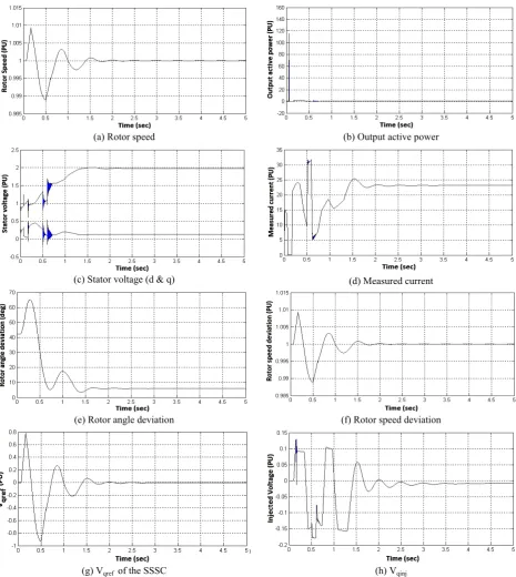
(g) Vqref of the SSSC (h) Vqinj
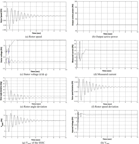
Fig. 7 Representation of the rotor speed, output active power, stator voltage, measured current, rotor angle deviation, rotor speed deviation, Vqref of the SSSC that coming from output of the controller and Vqinj (reference value of quadrature-axis injected
voltage) with the one 100 msec three-phase fault at transmission line, using LLC (time variation from 0 sec to 10 sec). Fig. 6 The block diagram of the SMIB.
For illustrating the ability of the proposed controller, operation of the ANFISC and LLC are investigated in Figs. 7 and 8 with the one 100 msec three-phase fault at transmission line. This three-phase fault is applied at the middle of one transmission line connecting bus-2 and bus-3 (infinite bus), at t = 0.5 sec.
The rotor speed, output active power, stator voltage, measured current, rotor angle deviation, rotor speed deviation and Vqref signal, that connected the controller
to the input of the SSSC, are represented in the Fig. 7 for situation that the LLC is used, and Fig. 8 for situation that the ANFISC is used.
(a) Rotor speed (b) Output active power
(c) Stator voltage (d & q) (d) Measured current
(e) Rotor angle deviation (f) Rotor speed deviation
(g) Vqref of the SSSC (h) Vqinj
Fig. 8 Representation of the rotor speed, output active power, stator voltage, measured current, rotor angle deviation, rotor speed deviation, Vqref of the SSSC that coming from output of the controller and Vqinj (reference value of quadrature-axis injected
voltage) with the one 100 msec three-phase fault at transmission line, using ANFISC (time variation from 0 sec to 5 sec).
Table 2 Comparison of the overshoot and settling time in two cases, using ANFSC and PI controller.
Works Overshoot
Settling Time
PID (rotor speed deviation) 1.2 (%)
3.5 (sec)
This work (rotor speed deviation) 0.9 (%)
2 (sec)
PID (rotor angle deviation) 25 (deg)
3 (sec)
This work (rotor angle deviation) 22 (deg)
1.5 (sec)
From figures it is clear that the ANFISC has the better stability against disturbance, faster damping ability and lower overshoot with fewer ripples toward LLC. These parameters show that the ANFISC are more suitable from LLC for power flow controlling of the three-phase power transmission line with SSSC. Also from simulation results we found that the proposed intelligent controller has a convergence and stable control behavior after fault in the short time. Also the power system stability enhancement is improved using this controller.
Table 2 compares two parameters, overshoot and settling time, between the designed ANFISC and PI, which its coefficients are extracted from Ref. [2] and are represented in the Appendix C. As shown in the table, the proposed controller has less overshoot and lower settling time toward the PI controller.
7 Conclusion
In this paper, a SSSC controller based on the mixing of the FL and NN, for improvement of the damping ability of SSSC FACTS device, with the ANFISC short name, for SMIB transmission line, is successfully designed. The FL design is implemented using a five-layers NN. The architecture of the NN-based system has 2-14-49-49-1 nodes in the five-layers, respectively. The learning process is the hybrid method based on the FSBEBP using the one error signal as a key parameter of the learning, and propagates the error signal to the backward of the NN, for updating of the parameters. The proposed controller has several advantages, such as simple structure, learning capability, high adaptive operation, damping ability and medium nodes in hidden layers. Because of using the FL and NN ANFISC does not require an accurate model of the system and can be applied in the wide range of the FACTS controllers. The simulation results show that the designed controller, in comparison with the classic LLC and PI controller, can yield a better dynamic performance with the shorter overshoot, less settling time and better damping ability.
Appendix
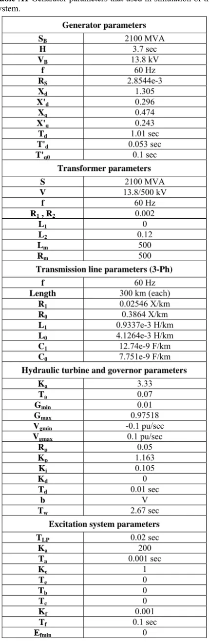
All data are in PU unless specified otherwise. Tables A1, A2 and A3 contain these data.
Table A1 Genarator parameters that used in simulation of the system.
Generator parameters
SB 2100 MVA
H 3.7 sec
VB 13.8 kV
f 60 Hz
RS 2.8544e-3
Xd 1.305
X'd 0.296
Xq 0.474
X'q 0.243
Td 1.01 sec
T'd 0.053 sec
T'q0 0.1 sec
Transformer parameters
S 2100 MVA
V 13.8/500 kV
f 60 Hz
R1 , R2 0.002
L1 0
L2 0.12
Lm 500
Rm 500
Transmission line parameters (3-Ph)
f 60 Hz
Length 300 km (each)
R1 0.02546 X/km
R0 0.3864 X/km
L1 0.9337e-3 H/km
L0 4.1264e-3 H/km
C1 12.74e-9 F/km
C0 7.751e-9 F/km
Hydraulic turbine and governor parameters
Ka 3.33
Ta 0.07
Gmin 0.01
Gmax 0.97518
Vgmin -0.1 pu/sec
Vgmax 0.1 pu/sec
Rp 0.05
Kp 1.163
Ki 0.105
Kd 0
Td 0.01 sec
b V
Tw 2.67 sec
Excitation system parameters
TLP 0.02 sec
Ka 200
Ta 0.001 sec
Ke 1
Te 0
Tb 0
Tc 0
Kf 0.001
Tf 0.1 sec
Efmin 0
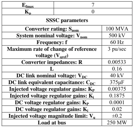
Efmax 7
Kp 0
SSSC parameters
Converter rating: Snom 100 MVA
System nominal voltage: Vnom 500 kV
Frequency: f 60 Hz
Maximum rate of change of reference voltage (Vqref)
3 pu/sec
Converter impedances: R 0.00533
L 0.16
DC link nominal voltage: VDC 40 kV
DC link equivalent capacitance: CDC 375μF
Injected voltage regulator gains: KP 0.00375
Injected voltage regulator gains: Ki 0.1875
DC voltage regulator gains: KP 0.0001
DC voltage regulator gains: Ki 0.02
Injected voltage magnitude limit: Vq ±0.2
Load at bus 250 MW
Table A2 Parameters of the LLC that used in simulation of the system as a classic controller.
LLC parameters Gain Block: Ks 54.4917
Washout Block: Tw 10
LLC Block: T1s 0.7802
F 60 Hz
T2s 0.3673
T3s 0.3051
T4s 0.3909
Table A3 Parameters of the PI controller that used in simulation of the system as a classic controller.
PI controller parameters
KP 72.9294
KI 0.01
References
[1] S. Panda, S. C. Swain, P. K. Rautray, R. K. Malik and G. Panda, “Design and Analysis of SSSC-based Supplementary Damping Controller”, Journal of Simulation Modelling Practice and Theory, Vol. 18, No. 9, pp. 1199-1213, 2010. [2] S. C. Swain, S. Mahapatra, S. Panda and S.
Panda, “Design of DE Optimized SSSC-based FACTS Controller”, Journal of Electronics and Electrical Engineering, Vol. 2, No. 4, pp. 12-27, March 2010.
[3] A. Kazemi, A. Badri and S. Jadid, “Investigation of Two Vector Control based Method for Static Synchronous Series Compensator”, Iranian Journal of Electrical & Electronics Engineering, Vol. 1, No. 4, pp. 1-6, Oct. 2005.
[4] A. S. Kannan and R. Kayalvizhi, “A Novel Design of a Fuzzy Coordinated SSSC Controller for Integrated Power Systems”, Journal on
Technicaland Physical Problems of Engineering, Vol. 3, No. 3, pp. 6-16, Sep. 2011.
[5] A. D. Falehi, “A Robust Approach based on PSO Technique to Alleviate Power System Oscillation using SSSC-based PSD Damping Controller”, Journal of Electrical Review, Vol. 88, No. 8, pp. 177-181, 2012.
[6] G. MadhusudhanaRao and B. V. SankerRam, “A Neural Network based Speed Control for DC Motor”, Journal of Recent Trends in Engineering, Vol. 2, No. 6, pp. 121-124, Nov. 2009.
[7] S. R. Jalluri and B. V. S. Ram, “A Neuro-Fuzzy Controller for Induction Machines Drives”, J. of Theoretical and Applied Information Technology, Vol. 19, No. 2, pp. 102-108, Sep. 2010.
[8] M. Neshat, A. Adeli, A. Masoumi and M. Sargolzae, “A Comparative Study on ANFIS and Fuzzy Expert System Models for Concrete Mix Design”, Journal of Computer Science Issues, Vol. 8, No. 3, No. 2, pp. 196-210, May 2011. [9] D. Nauck, F. Klawon and R. Kruse, Foundations
of Neuro-Fuzzy Systems, J. Wiley & Sons, 1997. [10] J. Vieira, F. M. Dias and A. Mot, “Neuro-Fuzzy
Systems: A Survey”, WSEAS Transactions on Systems, Vol. 3, No. 2, pp. 414-419, 2004.
[11] M. R. Homaeinezhad, E. Tavakkoli, A. Afshar, A. Atyabi and A. Ghaffari, “Neuro-ANFIS Architecture for ECG Rhythm-Type Recognition using Different QRS Geometrical-Based Features”, Iranian Journal of Electrical & Electronic Engineering, Vol. 7, No. 2, pp. 70-83, 2011.
[12] S. Tano, T. Oyama and T. Arnould, “Deep Combination of Fuzzy Inference and Neural Network in Fuzzy Inference”, J. on Fuzzy Sets and Systems, Vol. 82, No. 2, pp. 151-160, 1996. [13] R. Jang, Neuro-Fuzzy Modeling: Architectures,
Analysis and Applications, Ph.D. Thesis, University of California, Berkley, July 1992. [14] A. Ghaffari, M. R. Homaeinezhad and M.
Akraminia, “Discrimination of the Heart Ventricular and Atrial Abnormalities via a Wavelet-Aided Adaptive Network Fuzzy Inference System (ANFIS) Classifier”, Iranian Journal of Electrical & Electronic Engineering, Vol. 6, No. 1, pp. 1-19, March 2010.
[15] D. Nauck, “Beyond Neuro-Fuzzy Systems: Perspectives and Directions”, Third European Congress on Intelligent Techniques and Soft Computing, pp. 1159-1164, 1995.
[16] C. F. Juang and C. T. Lin, “An On-line Self Constructing Neural Fuzzy Inference Network and Its Applications”, IEEE Transactions on Fuzzy Systems, Vol. 6, No. 1, pp. 12-32, 1998. [17] N. Kasabov and Q. Song, Dynamic Evolving
Fuzzy Neural Networks with ‘m-out-of-n’ Activation Nodes for On-line Adaptive Systems,
Technical Report (TR99/04), Dep. of Information Science, University of Otago, March 1999. [18] Y. Q. Zhang and A Kandel, “Compensatory
Neuro-Fuzzy Systems with Fast Learning Algorithms”, IEEE Trans. on Neural Networks, Vol. 9, No. 1, pp. 83-105, Jan. 1998.
[19] T. C. Lin and C. S. Lee, “Neural Network based Fuzzy Logic Control and Decision System”, IEEE Transactions on Computers, Vol. 40, No. 12, pp. 1320-1336, Dec. 2009.
[20] A. Kazemi, M. Ladjevardi and M. A. S. Masoum, “Optimal Selection of SSSC-based Damping Controller Parameters for Improving Power System Dynamic Stability using Genetic Algorithm”, Iranian Journal of Science and Technology, Transaction B, Engineering, Vol. 29, No. B1, pp. 1-10, 2005.
[21] S. Panda, N. P. Padhy and R. N. Patel, “Power System Stability Improvement by PSO Optimized SSSC-based Damping Controller”, Journal of Electric Power Components and Systems, Vol. 36, No. 5, pp. 468-490, 2008.
[22] A. H. Niasar, M. A. S. Masoum and H. Moghbeli, “Adaptive Neuro-Fuzzy Intelligent Controller via Emotional Learning for Indirect Vector Control (IVC) of Induction Motor Drives”, 12th Iranian Conf. on Electrical Eng., pp. 1-6, 11-13, 2004. [23] R. Sivakumar, C. Sahana and P. A. Savitha,
“Design of ANFIS-based Estimation and Control for MIMO Systems”, Journal of Engineering Research and Applications, Vol. 2, No.. 3, pp. 2803-2809, May-Jun 2012.
[24] S. S. Roy, “Design of Adaptive Neuro-Fuzzy Inference System for Predicting Surface Roughness in Turning Operation”, Journal of Scientific and Industrial Research, Vol. 64, pp. 653-659, Sep. 2005.
[25] P. K. Dash, S. K. Panda, T. H. Lee, J. X. XU and A. Routray, “Fuzzy and Neural Controllers for Dynamic Systems: An Overview”, IEEE Proc. on Power Electronics and Drive Systems, Vol. 2, pp. 810-816, 1997.
[26] C. Lin and Y. Lu, “A Neural Fuzzy System with Fuzzy Supervised Learning”, IEEE Transaction on Systems, Man and Cybernetics, Vol. 26, No. 5, pp. 744-763, Oct. 1996.
[27] G. Shahgholian and A. Movahedi, “Modeling and Controller Design using ANFIS Method for Non-linear Liquid Level System”, Journal of Information and Electronics Engineering, Vol. 1, No. 3, pp. 271-275, Nov. 2011.
[28] J. Jang, “Self Learning Fuzzy Controller based on Temporal Back-Propagation”, IEEE Trans. on Neural Network, Vol. 3, No. 5, pp. 714-723, 1992.
Alireza Khoshsaadat received his B.Sc. degree in Electronic Engineering from Department of Electrical and Computer Engineering, Shahid Beheshti University (SBU), Tehran, Iran in 2009, and M.Sc. degree in Electronic Engineering from Department of Electrical Engineering, Iran University of Science and Technology (IUST), Tehran, Iran in 2011. He is currently Ph.D. student at Amirkabir University of Technology (AUT), Tehran, Iran. His research interests include modeling and design of power electronics converters, artificial intelligence-based control systems and digital control by FPGA.
Mohammad-Reza Mosavi received his B.Sc., M.Sc., and Ph.D. degrees in Electronic Engineering from Iran University of Science and Technology (IUST), Tehran, Iran in 1997, 1998, and 2004, respectively. He is currently faculty member of Department of Electrical Engineering of IUST as professor. He is the author of about 190 scientific publications on journals and international conferences. His research interests include circuits and systems design.
Javad Shokrollahi Moghani was born in Tabriz, Iran in 1956. He received the B.Sc. and M.Sc. degrees in Electrical Engineering from the South Bank Polytechnic and Loughborough University of Technology, England, in 1982 and 1984, respectively. Since 1984 until 1991 he was with the Department of Electrical Engineering, Amirkabir University of Technology, Tehran, Iran. He received his Ph.D. degree in Electrical Engineering from Bath University, Bath, England in 1995 and is back to Amirkabir University of Technology since. His research interests include electromagnetic system modeling and design using FEM, DC-DC converters and electric drives.
Arash Khoshooei received the B.Sc. degree in Electrical Engineering from Shahid Chamran University, Ahvaz in 2001 and the M.Sc. degree from Amirkabir University of Technology, Tehran, Iran in 2003. From 2006 to 2012, he was with the Department of Electrical and Computer Engineering, Jondishapur University of Technology. He is currently pursuing the Ph.D. degree at Amirkabir University of Technology (AUT), Tehran, Iran. His research interests include modeling and control of power electronics converters.