Three-Dimensional Digital Recording and Modelling Methodologies for Documentation and Reconstruction of the Newport Medieval Ship
‘A thesis submitted to the University of Wales Trinity Saint David
in fulfilment of the requirements for the degree of Doctor of Philosophy’
2015
3
Abstract:
The following thesis presents the three-dimensional digital documentation methods and modelling approaches used during the excavation and post-excavation research phases of the Newport Medieval Ship Project. The primary case study is the
Newport Medieval Ship, a large clinker-built merchant vessel discovered in 2002 in Newport, Wales, United Kingdom. The use of accurate and efficient
4
Contents
Abstract: ... 3
Contents ... 4
List of Figures ... 11
List of Tables ... 28
List of Digital Data Files Appended on Enclosed DVD ... 29
Acknowledgements ... 30
The author’s role in the Newport Medieval Ship Project ... 33
Online Digital Archive and Appended Digital Data ... 37
A note about terminology ... 38
Chapter 1: Introduction to the Newport Medieval Ship Project ... 39
Introduction ... 39
Background – Discovery and Description ... 42
Newport Medieval Ship Timber Function Codes ... 47
Description of the Hull ... 55
Outer Hull ... 57
5
Inner hull ... 62
Disarticulated Timbers and Artefacts ... 66
Summary ... 68
Chapter 2: Conceptual Approaches to Hull Form Documentation in Nautical Archaeology: The Development of in situ Archaeological Ship Recording and Post-Excavation Individual Ship Timber Recording ... 69
Introduction ... 70
The Documentation and Reconstruction Debate ... 72
Ship Find Documentation ... 78
The Rother Barge ... 79
The Nydam Bog Excavations ... 80
The Gokstad vessel ... 81
The Oseberg Ship ... 84
Ladby Excavation ... 87
Sutton Hoo ... 88
The Skuldelev Vessels ... 92
Yassi Ada 7th Century AD Shipwreck ... 96
Blackfriars 1... 99
6
Mary Rose ... 106
The Hedeby Harbour Wrecks ... 106
Red Bay Shipwrecks ... 109
Barland’s Farm Boat ... 113
Magor Pill Vessel ... 114
La Belle ... 116
Renaissance ships from Copenhagen ... 118
The Roskilde vessels ... 122
The Doel Cog ... 125
The Newport Medieval Ship ... 126
Sørenga 7 Shipwreck ... 127
The Barcode Wrecks ... 129
Summary of in situ ship find documentation techniques ... 131
Traditional Post-Excavation Ship Timber Documentation Techniques ... 135
A History of Contact Digitising In Nautical Archaeology ... 138
Contact Digitising in Practice ... 138
Using Contact Digitisers to record ship’s timbers ... 140
The Early Days: from the 1990s to 2005 ... 143
7
Chapter 3: The Documentation of the Newport Medieval Ship ... 158
Introduction ... 159
Initial Recording Trials ... 160
Recording the Newport Medieval Ship Timbers ... 165
Arranging the Workspace and Setting-Up the Contact Digitiser ... 171
Using the Contact Digitiser ... 182
Control Points ... 189
Rhinoceros3D modelling software ... 191
Templates ... 192
Toolbars and Tools ... 193
The Layering System ... 197
Layer Names and Descriptions ... 203
Reorientation and Calibration ... 220
Checking the Digital Record ... 223
Archiving ... 228
The Utility and Comparability of Data Sets Produced Using Contact Digitisers .. 232
8 Newport Ship Hull Plank Metrical Data Capture Exercise: Process and Results
... 236
Aber Wrac’h 1 and Newport Medieval Ship Hull Plank Comparison Case Study. 247 Comparison of Digitally Recorded Newport Medieval Ship Timbers Before and After Conservation Treatment ... 256
The Growth of Contact Digitising in Nautical Archaeology 2006-2014 ... 264
The Drogheda Boat and the Traditional Boats of Ireland Project ... 266
Norwegian Maritime Museum ... 268
Deutsches Schiffahrts Museum (German National Maritime Museum) ... 268
The University of Southern Denmark ... 269
The Center for Maritime Archaeology and Conservation at Texas A&M University ... 269
Doel Kogge Project in Antwerp, Belgium ... 270
The Swash Channel Wreck and Bournemouth University ... 274
Viking Ship Museum, Roskilde, Denmark ... 275
The Yenikapı Shipwreck Project ... 276
Arles-Rhône 3 Documentation Project ... 282
Faro-Rhino Archaeological Users Group (FRAUG) ... 283
9
Introduction ... 285
Digital Modelling Process Overview ... 286
Recognition of Distortion in the individual Hull timbers ... 300
Master Composites ... 305
Chapter 5: Physical Modelling Methodologies ... 322
Introduction ... 322
Rapid Prototyping Technology and Equipment ... 324
Materials ... 327
Test pieces: Identifying and Refining Ideal Production Parameters ... 328
Additive Manufacturing: The Selective Laser Sintering Process ... 331
Assembly of the Physical Scaled Model ... 336
Documentation of the physical model shape during and after assembly ... 351
Laser Scanning the Physical Scale Model ... 355
Laser Scanning Equipment and Methodology ... 358
Documentation Results ... 361
The use of Ribbands to Ghost in the Missing Areas of the Original Hull ... 366
10
Similar approaches on other projects ... 385
Prince’s Channel Wreck ... 385
Norwegian Maritime Museum – The Sørenga 7 shipwreck ... 386
Drogheda Boat Recording, Modelling and Reconstruction ... 388
The Doel Kog and the Roskilde Wrecks ... 388
Chapter 6: Conclusions... 390
The Potential of Digital Documentation and Modelling Approaches in Nautical Archaeology ... 390
Digital documentation and the Newport Ship: The production of a trustworthy and versatile dataset ... 393
The Future of In Situ Documentation ... 396
The Future of Post-Excavation Documentation ... 402
The Future of Digital Modelling and Analysis... 404
Conclusion ... 413
11
List of Figures
Figure 1. The in situ remains of the Newport Medieval Ship. The port side is to the right. ... 43
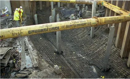
Figure 2. Excavated hull remains pierced by numerous concrete piles. Port side is to
the left. ... 44
Figure 3. Plan view of site showing disarticulated material found inside of the hull.
Dendrochronological dates for selected disarticulated timbers are also shown. ... 46
Figure 4. Removing an iron bolt from a large standing knee. ... 48
Figure 5. Dried-out composite cross-beams recovered during the excavation. Note
the hooked scarf joints. ... 49
Figure 6. Archaeologist cleaning the joggles and rebates on the outboard surface of
a framing timber. ... 50
Figure 7. Concretions obscuring the outboard surface of a hull plank. The reddish
stains are the remnants of the corroded wrought iron nails and roves. ... 51
Figure 8. Parallel inscribed lines on the inboard face of a hull plank, possibly
representing count marks. ... 51
Figure 9. Converging inscribed lines on the inboard face of a hull plank. Note the
rove impression in the upper left corner. ... 52
Figure 10. Typical filled-in timber record sheet containing a description of the
timber, along with wood science notes and outstanding actions. ... 53
Figure 11. Section view of beech keel (CT 1641) with oak garboard strake (CT1644)
12 Figure 12. View of the lapstrake hull with all inner hull timbers and framing timbers
removed. ... 58
Figure 13. A typical floor timber from amidships. Note the centreline limber hole. 59
Figure 14. Alternating pattern of asymmetric floor timbers amidships. ... 61
Figure 15. Joggled and rebated outboard face of a framing timber. Note the
well-preserved tool stop marks. ... 62
Figure 16. Typical braces found on either side of the mast step/keelson. ... 64
Figure 17. 3D rendered wireframe drawing of the forward-most section of keelson.
Note the squared treenails inserted at opposing angles to fasten the keelson to the
underlying floor timbers. ... 65
Figure 18. Framing timbers arranged in tank for wet storage and conservation
treatment. Photograph taken between water bath changes. The tanks measured 10
metres by 5 metres with a depth of 0.5 metres. ... 66
Figure 19. The Viking-age Gokstad vessel in Oslo, Norway. ... 83
Figure 20. The Viking-age Oseberg vessel in Oslo, Norway. ... 86
Figure 21. The excavation of the Ladby Ship. Individual fasteners were identified
with metal tags and strakes delineated by string ... 88
Figure 22. Excavation of the Sutton Hoo ship in 1939, looking aft. Note the rows of
concreted fasteners and shadows of the original strakes. Archaeologists worked
from the swing visible in the aft part of the vessel, in order to avoid damaging the
13 Figure 23. Stereo-photogrammetrical documentation of Skuldelev Wreck 3 and
associated barrier material. Excavation site plans were later created from the stereo
pairs.. ... 93
Figure 24. The Viking-age Skuldelev vessels in Roskilde, Denmark. ... 95
Figure 25. Artist's rendering of the Yassi Ada 7th Century Shipwreck excavation.
Note the stepped framework of angle iron covering the site and the photography
towers in the lower left and centre right. ... 97
Figure 26. Archaeologists recording the position of finds on the 7th Century AD
Yassi Ada shipwreck. The grid square measures 2m x 2m, and is further subdivided
into one hundred 200mm x 200mm squares.. ... 98
Figure 27. Excavation and documentation of the Blackfriars I vessel in 1962. The hull
remains were disassembled and raised, allowing for detailed post-excavation
documentation. ... 101
Figure 28. Documenting the in situ hull remains of the Graveney boat in Kent, England in 1970. . ... 103
Figure 29. Archaeologist using direct contact tracing to document a plank from the
Graveney boat.. ... 105
Figure 30. Full scale elevated plane tracing of timbers from the Hedeby I ship.. ... 108
Figure 31. During underwater excavations of the 24M vessel in Red Bay, Labrador,
14 Figure 33. During the excavation of La Belle, archaeologists used a Sokkia SET5E total station to plot the 3D position of all hull timbers and artefacts, prior to
recovery... 117
Figure 34. The use of a total station to measure in points on the hull of one of the
Renaissance Ships in Copenhagen.. ... 120
Figure 35. Archaeologist using the Direct Survey Method technique on a submerged
site in Cyprus. Multiple measurements are taken between fixed datums and several
points on an object, allowing for the creation of a 3D network of points describing
the spatial relationship between objects. . ... 123
Figure 36. Documenting a ship's timber using a contact digitiser at the Viking Ship
Museum in Roskilde, Denmark in 2004. ... 124
Figure 37. Archaeologist using a FaroArm contact digitiser to document a brace
from the Newport Ship. ... 139
Figure 38. The recording workshop at the Viking Ship Museum in Roskilde,
Denmark, was set up in an efficient way that allowed the timber recorder ready
access to a variety of tools besides the digitiser, including digital cameras and
specialised lighting, allowing them to simultaneously document multiple aspects of
the timber while minimising handling. ... 148
Figure 39. A Cimcore Immersion Microscribe Stinger II contact digitiser belonging to
the Netherlands Institute for Ship and Underwater Archaeology in Lelystad. ... 151
Figure 40. Archaeologist using a Cimcore Immersion Microscribe Stinger II contact
15 Figure 41. A FaroArm contact digitiser magnetically clamped to a portable heavy
steel base. ... 154
Figure 42. Newport Ship Recording Trials. Using a laser scanner to document a
stringer. ... 161
Figure 43. Newport Ship Recording Trials. Documenting a ship's timber using
elevated plane tracing. ... 162
Figure 44. Newport Ship Recording Trials. Using a contact digitiser to document a
floor timber. ... 163
Figure 45. The Newport Medieval Ship Centre. Timbers were organised by function
(planks, framing timbers, stringers, etc. and placed in tanks for storage. Note the
mobile overhead gantry, used to handle larger timbers, in the top left. ... 166
Figure 46. Four identical contact digitiser work stations were created to efficiently
record the large assemblage. ... 167
Figure 47. Sampling tar and animal hair for analysis. Multiple samples were taken
along the lands and scarfs of the planking, with the sample positions marked with
map pins. These pins (and temporary labels) were removed after documenting their
position with the contact digitiser. ... 168
Figure 48. The cover of the Timber Recording Manual, which was used to train staff
in the documentation methodology used at the Newport Ship Project. ... 170
Figure 49. Archaeologist using a contact digitiser to record one of the large struts
16 computer monitors allowed for flexible approaches to setting up the workspace.
... 172
Figure 50. FaroArm Base extension tube. This 300mm long threaded tube increased
the range of the contact digitiser considerably. ... 174
Figure 51. Contact digitiser supported by a counterbalance system suspended from
a carriage and cable. ... 175
Figure 52. The use of large LCD monitors enabled archaeologists to work at
considerable distance from the screen and still see details. ... 177
Figure 53. The use of padded slings and thick foam was essential in order to prevent
damage when moving the large timbers. ... 179
Figure 54. A mobile overhead gantry was used to lift and move the larger ship
timbers. ... 180
Figure 55. The position of the x,y, and z orientation points when setting up the work
space. ... 184
Figure 56. The pistol-grip handle and custom made probe tip holder of the FaroArm
contact digitiser. ... 185
Figure 57. Machined FaroArm contact digitiser probe tip holder with a non-marking
PDA stylus used as a probe tip. ... 186
Figure 58. Counterbalance, carriage and custom probe tip holders used in
conjunction with the FaroArm contact digitiser. ... 187
Figure 59. Using the contact digitiser to record the position of control points prior
17 Figure 60. Graphical user interface of the Rhinoceros3D modelling software. The
archaeologist can see the curves captured by the contact digitiser appear in the
drawing in real time. ... 191
Figure 61. Timber Recording Toolbar used by the Newport Ship Project. ... 193
Figure 62. Curve Degrees. Degree 1 curves pass through all control points, while
higher degree curves can deviate from the control points. ... 196
Figure 63. The layering system used by the Newport Ship Project. Note the
alphanumeric codes preceding each layer name. ... 198
Figure 64. Annotated digital drawing of the inboard face of a typical hull plank from
the Newport Ship. ... 201
Figure 65. Annotated digital drawing of the outboard face of a typical hull plank
from the Newport Ship. ... 202
Figure 66. Calibrating the FaroArm contact digitiser. This important check was
performed at least once a week, and ensured that the device was in peak operating
condition. ... 222
Figure 67. Print-out of a four-sided digitally recorded timber. The archaeological
consultant would compare the details in the drawing to the features on the timber
and note any deficiencies. ... 224
Figure 68. Annotated print-out of a two-sided timber. Any notes are incorporated in
the database, while any necessary corrections are made to the original digital
18 Figure 69. A typical hull plank from the Newport Ship. This 2D drawing has been
created from the original 3D wireframe ... 234
Figure 70. On the port side of the ship, there were areas where each successive
strake tended to have a scarf slightly further forward than the one on the strake
below. There was a clearly visible pattern between P2 and P10 and between F30
and F45. ... 239
Figure 71. Nail head impression and hole on the outboard face of a hull plank. Note
the star-shaped impression left by a maker's mark on the underside of the nail
head. ... 241
Figure 72. Four sintels or staples were used to close a crack on this hull plank. .... 242
Figure 73. Outboard tingle fastened to a hull plank. The surface between the plank
and tingle was filled with tar and animal hair and typically used to patch areas of
cracking in the original lapstrake hull planking. ... 244
Figure 74. Treenail head on the outboard face of a hull plank. The dimple was
created by a lathe during the manufacturing process. ... 245
Figure 75. Faceted head of a treenail seen on the outboard face of a hull plank. .. 246
Figure 76. Wedged Treenail head seen on the outboard face of a hull plank. ... 247
Figure 77. Using a FaroArm contact digitiser and associated laser scanner to
document a stringer from the Aber Wrac'h 1 vessel. The emitted laser from the
19 Figure 78. Laser scan data of toolmarks, rebates and fastener heads was integrated
into the wireframe drawings using Rhinoceros3D Version 5.0, which allowed both
data sets to be positioned and viewed simultaneously... 251
Figure 79. Using a FaroArm contact digitiser to document the outboard face of a
stringer recovered from the Aber Wrac'h 1 vessel. ... 253
Figure 80. Comparison of the digital records of two medieval lapstrake port side hull
planks. The top plank is from the Aber Wrac'h 1 vessel, and the bottom plank is
from the Newport Ship. Both timbers are at the same scale. ... 254
Figure 81. Recording a conserved (freeze-dried) plank from the Newport Ship. .... 258
Figure 82. Digital recording of floor timber F50_0 after PEG pre-treatment and
vacuum freeze-drying. ... 259
Figure 83. The waterlogged and post-conservation digital records of CT333 S29_4.
There was a noticeable loss of surface detail evident, especially when comparing
the extent of inscribed lines still extant on the surface of the timber. ... 260
Figure 84. Digitally recording tool stop marks on a conserved floor timber. ... 261
Figure 85. Screen capture showing the location and degree of distortion of selected
treenail axes on part of floor timber F50_0, with the waterlogged timber treenail
axes in black and the conserved timber treenail axes in red. The corresponding
treenail centres were an average of 5.85% closer together after conservation
treatment, with an average distance between corresponding centres being
20 Figure 86. Archaeologists recording the Drogheda boat timbers using a contact
digitiser. ... 266
Figure 87. Students at the University of Southern Denmark learning how to use the
contact digitiser, associated laser scanner and relevant software... 270
Figure 88. The recording tables and contact digitiser arrangement used at the Doel
Kogge Project in Antwerp, Belgium. Note the moveable clamp with mounting ring in
the lower right. ... 272
Figure 89. Archaeologist at the Doel Kogge Project using a FaroArm contact digitiser
to document a ship's timber. Note the overhead framework and associated
photographic equipment and light sources. ... 273
Figure 90. Archaeologists handling bow castle timbers from the Swash Channel
Wreck. Newport Museums and Heritage Service ... 275
Figure 91. The in situ remains of one of the Yenikapı vessels found in Istanbul, Turkey. The ships were disassembled and later documented using a contact
digitiser. ... 277
Figure 92. The FaroArm contact digitiser used by the Istanbul University recording
team at the Yenikapı excavations. The digitiser was mounted to a rail that ran the entire c.10m length of the recording table. ... 281
Figure 93. Members of the Faro-Rhino Archaeological Users Group research
network learn about the Orca Marine plugin for Rhinceros3D at the Newport Ship
21 Figure 94. Solid modelling toolbar used in Rhinoceros3D to create digital solid
models from the wireframe drawings. ... 287
Figure 95. Vector graphics wire-frame drawing of a typical hull plank scarf. The
drawing was created using a contact digitiser and Rhinoceros3D software. ... 289
Figure 96. Vector graphics wire-frame drawing of a typical hull plank scarf with
simplified or rebuilt edges visible in blue. ... 290
Figure 97. Digital solid model of a typical hull plank with various facets and features
labelled. The digital solid model was produced from the 3D wireframe drawing. . 293
Figure 98. Modelling the fastener centres. The axes for the fasteners were created
by projecting or extending a curve between the inboard and outboard centres of
each fastener. ... 294
Figure 99. Pipes are created around each of the fastener axes. ... 296
Figure 100. Rendered view of a completed digital solid model of a plank with the
cow tag number (CT 374) visible. ... 297
Figure 101. Artist's impression of medieval Newport. Perspective view of town, with
the castle, wall, bridge and town pill (inlet) clearly visible. The Newport Ship can be
seen in the centre of the image. ... 301
Figure 102. There was distortion present in selected framing timbers at the scarf
joints, with some of the distal ends deflecting downward more than 100mm from a
fair curve. It is thought that this distortion was caused by the substantial amount of
22 Figure 103. Rendered perspective view of digitally modelled timbers in the
amidships area. The mast step/keelson can be seen in the centre, flanked by braces,
stringers and ceiling planks. The brown transverse elements are framing timbers.
... 306
Figure 104. Screen capture of the Inner Hull master composite, consisting of
wireframe drawings and mesh models of the mast step/keelson, braces, stringers,
ceiling and riders, along with several miscellaneous timbers. The bow is to the left.
... 308
Figure 105. Screen capture of the Framing master composite file. This plan view
depicts the vessel with the bow to the left. ... 309
Figure 106. Planking master composite. Bow is to the left. ... 311
Figure 107. Detail of Planking master composite. Bow is to the left... 312
Figure 108. Detail of the Planking master composite showing the forward-most
section of the keel and first three strakes of planking on the starboard side. Note
the hood ends. ... 312
Figure 109. Perspective view screen capture of the Framing master composite,
showing the mast step/keelson, braces and framing. Note the filler pieces used to
bring up the level of selected floor timbers. ... 313
Figure 110. Detail of the Inner Hull master composite showing the mast
step/keelson, braces, stringers and ceiling planks. Bow is to the left. ... 315
Figure 111. Plan view of the mast step/keelson and braces. Note the pump hole.
23 Figure 112. Perspective view of the mast step/keelson and braces. Bow is to the
left. ... 318
Figure 113. Perspective view of the inverted mast step/keelson and braces. Note
the rebates on the underside of the mast step/keelson where it fits over the floor
timbers. ... 319
Figure 114. Selective Laser Sintering (SLS) machine at the Manufacturing and
Engineering Centre at Cardiff University. The machine was capable of producing
several hundred scale model ship parts in each batch. ... 326
Figure 115. Test blocks were created in order to test the precision and accuracy of
the selective laser sintering machine. Comparisons were made between the
manufactured hole diameter and the nominal hole diameter (above in mm). These
test parts were included in each batch. ... 328
Figure 116. These blocks were arranged around the build chamber to test the ability
of the machine to accurately and consistently create small features (the fastener
holes) at the extreme edges of the build area. ... 330
Figure 117. Cross-section of shelled floor timber model. Note the shelling around
each treenail hole. Shelling reduced the manufacturing time. ... 332
Figure 118. Typical layout of a layer of modelled ship timber models in the selective
laser sintering machine. Each build comprised multiple layers of model pieces. ... 333
Figure 119. Completed framing timber scale model pieces. Digital solid models of
24 University. The finished physical model pieces from each batch were packaged and
then posted back to the ship centre. ... 335
Figure 120. The first batch of modelled pieces are prepared for assembly. The 1:10
scale model pieces were held together using threaded metal micro-fasteners. .... 337
Figure 121. Modelling table with protective shield in place. Members of the public
were able to view the assembly of the model during open days. ... 338
Figure 122. The author assembling strakes of planking. The sequence of
construction of the 1:10 scale model was visually documented using time-lapse
photography. ... 339
Figure 123. Planking was added to the model until reaching strake 16 on both the
port and starboard sides. ... 340
Figure 124. Framing timbers attached to the model up to the turn of the bilge. The
bow is to the right. ... 341
Figure 125. Outboard starboard surface of the inverted model. Note the tingles
(patches) modelled in red. ... 342
Figure 126. Completed laser sintered 1:10 scale model of the extant articulated
structural hull timbers. The ceiling planks and bilge boards were digitally recorded,
but not modelled, as they were not considered to affect the hull form. Note the
disarticulated composite beam/knee struture, which has been tentatively placed.
25 Figure 127. Threaded micro-fasteners used to assemble the hull form model. The
smaller black screws were used in clench nail holes, while the larger silver screws
were used in treenail holes. ... 344
Figure 128. Archaeologist attaching framing model pieces to the planking shell.
Note the camera and tripod set up in the background to take time-lapse
photographs. ... 346
Figure 129. Attaching the severed port bow section to the model. ... 347
Figure 130. Detail of the mast step/keelson and forward-most braces on the scale
model. Compare to Figure 131. Bow is to the left. ... 350
Figure 131. Detail of the in situ mast step/keelson and forward-most braces.
Compare to Figure 130. Bow is to the left. ... 350
Figure 132. The author laser scanning the inner surface of the completed 1:10 scale
hull model. ... 352
Figure 133. Experimental fitting of digital solid model pieces into the digitally
documented scaled physical hull form shape. ... 354
Figure 134. Digital mesh model produced from laser scanning the 1:10 scale hull
form model when the planking had reached the 16th strake on both the port and
starboard sides. Note the twist in the keel. ... 356
Figure 135. Perspective view of the digital mesh model produced from laser
scanning both the inner and outer surfaces of the scaled physical hull form model.
26 Figure 136. Digital mesh model produced from laser scanning the interior surface of
the assembled hull planking (through p16 and S16). ... 361
Figure 137. 1:30 scale laser-sintered model of the articulated hull remains. Bow is to
the left. ... 364
Figure 138. Detail of the 1:30 scale laser-sintered model of the articulated hull
remains. Note the removable human figure standing in the mast step rebate. Bow is
to the left. ... 365
Figure 139. Author fitting plastic transverse ribbands to the model. ... 366
Figure 140. Transverse ribbands were threaded through the inter frame spaces,
under the stringers (and keelson in amidships area), near every fifth frame station.
... 367
Figure 141. Transverse and longitudinal ribbands tentatively fitted to the model.
The metal 'bulldog' clips were used during the fairing process and were later
replaced with more permanent plastic cable ties. ... 368
Figure 142. The plastic ribbands were aligned to existing strake runs on the outer
hull surface of the scaled physical model. ... 369
Figure 143. The first attempt to create a keel extension and adjustable stern post.
... 370
Figure 144. The second attempt to create a suitable adjustable stern post. ... 371
Figure 145. Polycarbonate sheets were eventually used in both the bow and stern
to provide adjustable attachment points for the ends of the ribbands and planking
27 Figure 146. Dry-erase markers were used to draw on potential posts and planking
termination points. These tentative lines were later reinforced by using steel flat
stock clamped to the polycarbonate plates, providing firm anchor points for the
ends of the ribbands. ... 373
Figure 147. The transom stern fitted to the physical scaled model. ... 376
Figure 148. The physical scaled model was firmly attached to the modelling table
and the starboard twist in the bow and stern was largely removed by using clamps,
screws and braces to force the physical model into a more correct shape. ... 382
Figure 149. Final fairing of the model was achieved by comparing corresponding
measurements on the port and starboard sides of the model. ... 383
Figure 150. The completed 1:10 scale physical hull form model of the Newport
Medieval Ship with ribbands ghosting-in the missing areas of the hull. ... 384
Figure 151. Composite scaled physical hull form model of the late 16th century
Barcode 6 shipwreck at the Norwegian Maritime Museum. The 1:5 scale model was
created using a combination of laser sintered framing and hand-cut cardboard
planks. The same methodological processes used on the Barcode 6 shipwreck were
used to record and model the Sørenga 7 vessel. ... 387
Figure 152. The first batches of additively manufactured scaled model parts from
the Doel Kogge project. ... 389
Figure 153. Perspective view of the minimum reconstruction of the Newport
Medieval Ship. The minimum reconstruction consists of a single deck, castles, and
28 Figure 154. The advanced digital modelling has allowed for the formulation of
detailed drawings showing a laser scan of the completed physical model fitted into
the reconstructed hull form, graphically contrasting the recovered elements of the
hull against those that were missing. ... 406
Figure 155. Drawing showing the relationship between the archeologically
recovered material and those parts of the vessel that have been reconstructed from
indirect evidence. ... 407
Figure 156. Capital or principal reconstruction of the Newport Medieval Ship. The
reconstructed vessel has two full decks, three masts, and a total displacement of
393 tons. ... 408
Figure 157. Screen capture of the 3D digital model of the composite bilge pump
found during the ship excavation. There were at least four pump locations in use at
various times during the ship’s working life. ... 411
List of Tables
Table 1. Timber function codes applied during excavation and post-excavation of
29
List of Digital Data Files Appended on Enclosed DVD
File Name File Format File Size
001_P16_S16_interior_hull_planking_final.pdf PDF 44.5 MB
001_P16_S16_interior_hull_planking_final.wrp WRP 133.0 MB
002_full_interior_hull.pdf PDF 66.2 MB
002_full_interior_hull.wrp WRP 177.0 MB
003_full_exterior_hull.pdf PDF 40.0 MB
003_full_exterior_hull.wrp WRP 81.2 MB
004_bow_decimated.pdf PDF 7.9 MB
004_bow_decimated.wrp WRP 95.6 MB
005_Total_Hull.3dm 3DM 79.7 MB
005_Total_Hull.pdf PDF 44.4 MB
005_Total_Hull.stl STL 100.0 MB
005_Total_Hull.wrp WRP 94.2 MB
NMS_Scale_Model_Doc_WF_Data _Meshes.3dm 3DM 63.2 MB
30
Acknowledgements
Since its inception, the Newport Medieval Ship Project has relied on a
multidisciplinary approach to achieve the numerous archaeological research and
conservation goals. The complexity and scale of the post-excavation research
project has necessitated the use of a variety of specialists, too numerous to
individually name. However, several people have been instrumental in enabling the
project to succeed by securing funding or providing expert guidance. These include
Nigel Nayling at the University of Wales Trinity Saint David, Fred Hocker at the Vasa
Museum, and Pat Tanner at the University of Southampton. Special mention goes
to Kate Hunter, the initial Newport Ship Project leader, for her vision and drive,
which allowed the project to flourish.
Numerous people have been employed by the Newport Medieval Ship Project since
the post-excavation research programme began in 2004. The following people have
contributed to the cleaning, recording, modelling, conservation and administrative
aspects of the Newport Ship Project: Hefin Meara, Angela Karsten, Monika
Maleszka-Ritchie, Benjamin Jennings, Matthew Simmonds, Lise Brekmoe, Vassilis
Tsiairis, Stuart Churchley, Christina Jolliffe, Rosie Edis, Phillip Matthews, Jeroen
Vermeersch, Neil Stevenson, Glyn Bateman, Sophie Adamson, Morwenna Perrott,
Erica McCarthy, Emma Routley, Marie Jordan, Mike Lewis, Oliver Blackmore and
Linda Cronin.
Funding for the ship project (and this thesis) has been provided by Newport City
31 grants from public bodies and charities and private individuals. The Welsh
Government provided substantial funding for the excavation and initial storage of
the vessel remains. A generous grant from the Heritage Lottery Fund (HLF) provided
funding for the purchase of three contact digitisers and the appointment and
training of a sizeable team of archaeologists. The HLF funding also provided support
for a substantial education and outreach programme. Grants from the Arts and
Humanities Research Council (AHRC) facilitated the digital solid modelling and
physical solid modelling phases of the project, while grants from CyMAL (Welsh
Museums, Archives and Libraries) and underpinned the successful efforts to create
digital minimum and capital reconstructions of the vessel by Pat Tanner.
Additional support, advice and constructive criticism has been provided by the
Faro-Rhino Archaeological Users Group (FRAUG) network of marine archaeological
researchers. Colleagues from around Europe, including Mike Belasus, Holger
Schweitzer, Jens Auer, Nicolas Ranchin-Dundas, Tom Lenaerts, Tori Falck, Alexandra
Grille, Alice Overmeer, Frank Dallmeijer, Christian Thomsen, Johan van Laecke,
Morten Ravn, and Vibeke Bischoff, have provided useful feedback in the
development of digital recording and modelling. Mark Starr kindly provided
detailed information regarding the early history of contact digitising at Mystic
Seaport in Connecticut.
I would like to thank several members of the Nautical Archaeology Programme
faculty at Texas A&M University (TAMU) for their long-standing support and
32 advice over the years. Fellow students (and friends) from TAMU, Justin Leidwanger
and Troy Nowak, have also offered encouragement and advice. Thanks are also due
to Rod Bale, Jemma Bezant, Colin Green, Anaïs Pajot and Chuck Meide.
The Newport Ship Advisory Panel has also provided valuable feedback and peer
review at annual meetings and in detailed correspondence, especially Sean McGrail
and Ole Crumlin-Pedersen. On a more local level, members of the Friends of the
Newport Ship have provided financial support in the form of travel and conference
grants and served as volunteers in a variety of capacities. I want to personally thank
my parents, Howard and Kathy, and especially my wife Emma, for their support and
encouragement over the years. Finally, I want to dedicate this work to my son, Rory
33
The author’s role in the Newport Medieval Ship Project
The following section briefly describes my role in the Newport Ship Project, as well
as detailing the different research phases, funding sources and publication outputs
that have occurred over the duration of the project. It is hoped that this will provide
the reader with a better understanding of the scale and complexity of the project,
and my changing role within it.
The Newport Ship is owned by Newport City Council, with the Newport Museum
having archaeological and curatorial responsibility for the find. The ship project was
originally led by Kate Hunter, an archaeological conservator, with Nigel Nayling
serving as the project’s archaeological consultant. I began working for the Newport
Medieval Ship Project in November 2004. I was hired as an archaeological Project
Officer to help develop and refine a methodology for efficiently cleaning and
accurately recording the sizeable ship timber assemblage.
I was initially hired on a one-year fixed term contract in order to take part in a pilot
study exploring the application of digital documentation technology to
archaeological ship timber recording (I had recently graduated from Texas A&M
University with an MA in Anthropology and a specialisation in Nautical
Archaeology). I was trained in contact digitising by Ivan Conrad Hansen at the Viking
Ship Museum in Roskilde, Denmark, in November 2004. After this training period in
Denmark, the remainder of the first year was spent systematically cleaning and
recording timbers from the Newport Ship. At the end of the pilot study, the results
34 comprehensive work plan and timber recording manual (Jones, 2005: 12-15, Jones,
2013).
The results of this pilot study were used in an application to the Heritage Lottery
Fund in 2005. The grant application was successful, with the HLF providing
substantial funding for an expanded programme of cleaning and recording, set to
run between April 2006 and March 2008. During this phase of the project, a large
team was assembled to undertake the cleaning and recording work. In September
2006, I was promoted to recording coordinator, with a range of responsibilities,
including training and supervising the archaeological team. I was responsible for
maintaining quality control over the recording process and liaising with the
archaeological consultant (Jones, 2009a: 36-41, Jones, 2008: 85-88).
In January 2008, I started to work on a PhD in Archaeology at the University of
Wales in Lampeter, under the supervision of Professor Nigel Nayling (who remained
the Newport Ship Project archaeological consultant). This PhD research was
supported by the Newport Museum and Newport City Council, who covered the
tuition fees. The research I was undertaking was seen as relevant and valuable to
Newport City Council, as it furthered understanding of the archaeological material. I
have continued to work in my dual roles as a full-time employee of Newport
Museum and student at the University of Wales from 2008 to the present (June
2014).
In April 2008, I was promoted to Curator of the Newport Medieval Ship Project. In
35 the archive, preparing artefactual and environmental material for specialist
analysis, and promoting the ship project through the dissemination of
archaeological information through popular and academic publications, on public
open days, and at community lectures and academic conferences. During this
period, I worked on the development of digital and physical modelling
methodologies, looking specifically at the creation of a 3D physical scale model of
the remains of the Newport Ship. This innovative research into 3D digital and
physical solid modelling became one of the main subjects of my PhD research.
The digital and physical modelling methodologies used in the Newport Ship Project
were developed with support from an Arts and Humanities Research Council Large
Research Grant called ShipShape 3D. The principal investigator for the grant was
Nigel Nayling. In my role as Curator of the ship project, I was seconded to the AHRC
ShipShape 3D research grant. Around 30% of my time was made available for the
duration of the multi-year AHRC project. The physical manufacturing costs and
assembly of the 3D model were some of the research objectives financed by the
AHRC grant. I played a key role in this research, which was documented with
several articles outlining the project methodology and results (Jones, 2009b:
111-116, Jones and Nayling, 2011: 54-60, Nayling and Jones, 2012: 319-324, Soe et al.,
2011: 757-762, and Soe et al., 2012: 443-450).
The AHRC-funded research culminated in the creation of a physical scaled model of
the hull remains as well as a series of CAD files containing digital models of all of the
36 digitally documented, using laser scanning and contact digitising technology. These
hull form shape state data sets, along with the master composites, represent the
culmination of my PhD research.
These data sets are now being used as a starting point for minimum and capital
reconstruction research. Much of this subsequent research is currently being
carried out by Pat Tanner at the University of Southampton, as part of his PhD
research into digital hull form analysis. The advanced digital modelling research has
been funded by a CyMAL grant and by Newport City Council (Jones, Nayling &
Tanner, 2013: 123-130, Jones, Nayling & Tanner, Forthcoming).
The archaeological consultant, Nigel Nayling, and I have recently completed a
comprehensive summary of the research results from the Newport Medieval Ship
Project (Nayling and Jones, 2013). An online archive, hosted by the Archaeology
Data Service, has also been deposited and is now publically accessible (Nayling and
Jones, 2014a). It is envisioned that these resources will be used as definitive sources
of primary information relating to the ship project. A further article explaining the
structure and function of the online archive, as well as a book about the Newport
37
Online Digital Archive and Appended Digital Data
The text of this thesis occasionally makes reference to digital files, which the reader
may wish to download and view while reading through the text. Selected files are
available by accessing an online archive hosted by the Archaeology Data Service
(ADS)
(http://archaeologydataservice.ac.uk/archives/view/newportship_2013/index.cfm, with a DOI: 10.5284/1020898), while other files are available on a digital video disc
(DVD) inserted in the back cover of the first volume of the thesis. The location of
each file (whether online or on enclosed disc) is noted at each relevant point in the
text. Further information about the digital archive and associated digital file
38
A note about terminology
The terminology used in nautical archaeology to describe aspects of wooden
shipbuilding is quite specialised and the use of certain words instead of others still
generates debate within the field. This thesis generally follows the terminology (and
illustrated glossary) used by J. Richard Steffy in his book Wooden Ship Building and the Interpretation of Shipwrecks (Steffy, 1994). The text, although 20 years old,
remains a standard reference in the field and the reader may wish to consult it for
Chapter 1: Introduction to the Newport Medieval Ship Project
Introduction
The Newport Medieval Ship Project has provided a rare opportunity to base the
reconstruction of a large medieval merchant vessel on archaeological remains, as
opposed to relying solely on written historical sources or contemporary medieval
imagery and iconography. The use of accurate and efficient three-dimensional
digital recording methodologies has allowed for the development of innovative
approaches to organising, analysing, modelling and disseminating data about the
individual timbers and the overall original hull form. The meticulously documented
remains of the vessel have provided the basis for further hull form research,
including the creation of a convincing and accurate minimum reconstruction and a
well-supported capital reconstruction. The utilisation of advanced technology and
engineering, in the form of Rhinoceros3D modelling software, contact digitising and
rapid prototyping has enabled the project to develop and test a variety of new
methodologies for documenting and reconstructing ancient vessels. The
abovementioned areas of research and methodological development will be
explored in greater detail below.
The following thesis provides a brief overview of the Newport Medieval Ship,
including a description of the site and detailed construction information about the
vessel itself. A review of the in situ archaeological documentation approaches has been included, helping to place the recording methods used on the Newport Ship
excavation into context. The development, use and spread of contact digitising in
40 nautical archaeology is presented in detail. The thesis goes on to cover the
recording and reconstruction processes used to document individual timbers
through to the creation of a series of master composites showing all of the digitally
recorded and modelled articulated hull timbers in their right relative positions.
Full-size digital solid models of each individual hull timber have been created from the
digital records. These digital solid models were, in turn, scaled down to 1:10 and
manufactured using an additive manufacturing technology known as selective laser
sintering. The resulting scaled physical model pieces, made from a strong and
flexible nylon plastic called polyamide-12, were fastened together to create a 3D
scaled physical model of the recovered hull elements.
The scaled physical model of the hull form, representing the post-depositional
shape state of the vessel was digitised and used as a basis for further reconstruction
efforts, both physically and digitally. As more elements were added, the changing
shape of the physical model was captured using contact digitising and laser
scanning technology. A basic preliminary set of lines was digitally extracted from
the model using the abovementioned technology.
The physical model was then used as a foundation to which plastic fairing ribbands
were attached in order to ghost-in missing areas and reveal localised and global
damage and distortion. The hull remains had been subjected to damage and
distortion during the use life, deposition, excavation, storage and subsequent
41 were identified, recorded, analysed and later accommodated/rectified in the
reconstruction efforts.
At this point in the research process, the model and ribbands were physically
manipulated (i.e. forced) into a fairer hull form. The new shape state data, captured
with the contact digitiser and point clouds created by the laser scanner, served as
the building blocks for creating idealised surfaces and hull forms for use in
hydrostatic and hydrodynamic modelling and advanced reconstruction efforts. This
data is currently being utilised in a forthcoming PhD thesis by Pat Tanner at the
University of Southampton, who is using the final digital models and 3D point data
presented here as a starting point for creating construction drawings, sail plans, and
a detailed set of sailing characteristics, including comprehensive hydrostatic and
hydrodynamic calculations.
The Newport Ship has not yet been directly identified in the historical record,
however, it should be possible, through continued careful archaeological and
historical research, to identify its role in wider European social, political, and
economic history. While these areas of research are beyond the scope of this thesis,
it is hoped that the hull form documentation and research presented here will
provide, to interested scholars, a valuable and definitive resource about the
physical nature of the ship and the processes used to uncover that information. The
detailed digital records created for each timber, as well as the scaled models and
digital reconstructions, will ideally be used as blueprints by those tasked with
42
Background – Discovery and Description
The Newport Medieval Ship was discovered during the construction of the
Riverfront Theatre and Arts Centre, immediately adjacent to the River Usk in
Newport, Wales. The ship was found inside of a sheet pile coffer dam which was
inserted around the planned area of the theatre’s orchestra pit excavations (Figure
1). The first articulated hull remains were discovered in June 2002, and the hull was
subsequently uncovered over the next 12 weeks. The ship was then documented,
disassembled and raised, with the last timbers being removed from the main site in
December 2002. The bow of the ship, lying just outside the main coffer dam, was
excavated separately in April 2003 (Nayling and Jones, 2013).
The hull remains (26m x 8m) were buried under several metres of alluvial clay,
which helped preserve the timbers, but also caused some distortion due to the
immense overlying weight. In addition to damage caused by the coffer dam clipping
off portions of the port bow quarter and starboard stern quarter, numerous long
concrete piles (0.5m x 0.5m in section) were inadvertently driven through the hull,
45 During its use-life, the Newport Ship had been brought into an inlet or pill and was
positioned roughly perpendicular to the main river, with the stern facing the river
and the bow pointed inland. The ship had been brought into the pill in a
presumably lightship (un-ballasted) state on a high spring tide. The ship had been
supported by a cradle or strut arrangement made of roughly hewn logs. The
remains of the hull were found heeled over to the starboard side and resting on the
collapsed strut structure. The ship could have been purposely heeled over for repair
work, or it may have been upright and then rapidly heeled over during a possible
collapse of the struts, with the ship quickly filling with silt and water on the next
flooding tide. It appears that several holes were drilled through the planking of the
vessel in an effort to drain it, however, the hull filled up with sediment and water
before it could be successfully drained and righted. The weight of the overlying
sediment and the eventual waterlogging of the ship timbers caused the hull to
slowly distort over the strut logs and uneven ground of the inlet. At some point
after the deposition of the ship, substantial portions of it, including the upper works
and masts, appear to have been removed or salvaged, as evidenced by crude axe
marks along the upper portions of the surviving hull. Many major components of
the ship, such as stringers and beams, were missing from the articulated hull, as
evidenced by partial existing timbers, open scarf joints, empty mortises,
compression marks, and unexplained fastener holes. Numerous disarticulated but
presumed ship timbers were also found scattered across the site, both inside and
46 Figure 3. Plan view of site showing disarticulated material found inside of the hull.
47 Table 1. Timber function codes applied during excavation and post-excavation of the Newport Medieval Ship. Toby Jones.
Ship timbers were numbered and given function codes based on their location and
purpose (Table 1). The hull was disassembled by cutting through the wooden
treenails that fastened many of the main structural components together. The
wrought iron fasteners that were used to hold the ceiling planking in place and hold Newport Medieval Ship Timber Function Codes
Function Code Description
Beam Beam
BB Bilge board
BRP# Brace (chock) to keelson port side BRS# Brace (chock) to keelson starboard side CP#.# Port ceiling plank
CS#.# Starboard ceiling plank F#.# Framing timber F#.0 Floor timber
F#.[odd number] Framing timber port side F#.[even number] Framing timber starboard side Filler Filler Board
Head Barrel/Cask Head Hoop Barrel/Cask Hoop
Keel Keel
Knee Knee
P#.# Port side hull plank
R# Rider
S#.# Starboard side hull plank
Son Keelson
Stave Barrel/Cask Stave
Stem Stem Post
STRP#.# Stringer port STRS#.# Stringer starboard Tingle Tingle/patch timber
48 the clinker hull together had largely corroded, making the removal of these timbers
relatively straightforward. Several composite timbers were fastened together with
large wrought iron bolts and treenails. These timbers were lifted intact and the
bolts later removed prior to conservation treatment at the ship conservation centre
(Figure 4).
Figure 4. Removing an iron bolt from a large standing knee. Newport Museums and Heritage
Service.
Certain oversize timbers, like the mast step, stringers and keel, were cut on site to
facilitate their safe handling, lifting and removal. Most of the waterlogged timbers
were kept wet on site and then moved to a temporary store at the Corus Steel
49 Newport Medieval Ship Centre (at Unit 22, Maesglas Industrial Estate, NP20 2NN)
on the western edge of Newport. Several disarticulated timbers were inadvertently
allowed to dry out, but were retained (Figure 5). These important structural timbers
(primarily beams) were also recorded in their dry state and included in the hull form
modelling efforts.
Figure 5. Dried-out composite cross-beams recovered during the excavation. Note the hooked scarf joints. Newport Museums and Heritage Service.
The individual waterlogged ship timbers were carefully cleaned by archaeologists
and conservators using fresh water, dental tools, and tooth brushes, along with
hammers and chisels. The latter tools were necessary to remove the concreted
remains of the wrought iron fasteners (Figure 6). These concretions, made up of
iron corrosion products, alluvial clay, animal fibre and wood tar, were
systematically removed in order to expose the well preserved original surfaces of
the hull timbers (Figure 7). In places, original construction marks, or inscribed lines,
50 At the beginning of the cleaning process, a timber record sheet was created to help
track progress and record any unusual or noteworthy features (Figure 10). This
sheet accompanied the timber throughout the cleaning, documentation, and
checking process. The information on these sheets was later scanned and entered
into the project database.
51 Figure 7. Concretions obscuring the outboard surface of a hull plank. The reddish stains are the
remnants of the corroded wrought iron nails and roves.Newport Museums and Heritage Service.
Figure 8. Parallel inscribed lines on the inboard face of a hull plank, possibly representing count
52 Figure 9. Converging inscribed lines on the inboard face of a hull plank. Note the rove impression
53 Figure 10. Typical filled-in timber record sheet containing a description of the timber, along with
54 During cleaning, samples of wood tar and animal fibre (used as luting) were
sampled for later analysis. Wood identification slides and features like barnacles
were also collected for future analysis.
After cleaning, the timbers were documented using 3D contact digitisers and
selective laser scanning and photography. The digital data was collected using a
FaroArm contact digitiser and processed using Rhinoceros3D CAD software (see
Chapter 3 for a detailed description of the digital recording process). The digital
recording of each timber was checked by a different archaeologist before being
signed off as complete. All of the digital timber records were checked by the
project’s archaeological consultant for accuracy, omissions and attention to detail.
After final checks, the timbers were cleared to enter the conservation process.
Certain timbers were documented again after undergoing conservation treatment,
55
Description of the Hull
The Newport Medieval Ship was clinker-built, and can be conceived as consisting of
three layers, the outer hull of lapstrake planking, the framing, and the inner hull,
which consists of the mast step/keelson, stringers, ceiling and riders. The entire
extant articulated structural portion of the hull was made from oak (Quercus spp.), with the exception of the keel, which was made from beech (Fagussylvatica L.) (Figure 11). The outer layer consisted of radially split oak hull planks and tingles,
while the middle layer was primarily oak framing timbers converted from compass
grown timber. The inner layer of the hull consisted of sawn oak ceiling planks and
stringers, as well as braces, riders and the mast step/keelson, all of which had been
converted from oak.
In terms of overall size and amount of surviving timber, the Newport Medieval Ship
exceeded all other archaeologically excavated ship finds in the UK, with the
exception of Mary Rose. The large size of individual timbers and the sheer amount of surviving material presented challenges in terms of moving, storing and
recording the remains. In order to get a feel for the scale of the Newport Ship
project, it is necessary to first understand the general construction of the vessel and
56 Figure 11. Section view of beech keel (CT 1641) with oak garboard strake (CT1644) still attached. Newport Museums and Heritage Service.
The basic scantlings of the remaining hull timbers are summarised below. It should
be noted that the ranges and statistical averages in the following sections are
derived from a detailed metrical data analysis programme which collected
numerous measurements from complete and undamaged timbers (See Chapter 3).
Direct measurement tools within the Rhinoceros3D modelling software were used
to collect data such as centre to centre fastener spacing and linear dimensions from
the wireframe drawings. This data was collected for individual timbers on a
standard spread sheet template and then averages were taken by ‘drilling through’
57 Outer Hull
The outer hull of the Newport Ship consisted of planking and tingles, and was made
entirely of radially split oak. There were 35 strakes of planking surviving on the
starboard side and 17 strakes on the port side (Figure 12). There were
approximately 847 planks and plank fragments. Of these, 798 fragments could be
assigned to specific planks comprising 374 outer hull planks for which individual full
function codes are known (i.e. which strake and the relative position within that
strake). There were thirteen fragments each of both port-side and starboard-side
planking which could not be assigned to a specific plank (i.e. function code was P or
S) and a further 23 fragments of outer hull planking which could not be assigned to
a specific side of the ship.
The intact planks ranged in length from 1280mm to 4511mm, with a mean length of
2965mm (longer and shorter length planks were a distinct possibility, as many were
damaged during the initial salvage and later post-depositional site-formation
phase). The plank widths, when measured at the midpoint of the length, ranged
between 170mm and 256mm, with a mean width of 212mm. The planks ranged
between 11mm and 33mm thick, with an average thickness of 24mm along the
upper edge and 19mm along the lower edge. Planks widths tapered fairly evenly
towards the ends of the vessel, with the visible width (when measured on the
inboard face) ranging from an average of 176mm at F30 to an average of 147mm at
58 Figure 12. View of the lapstrake hull with all inner hull timbers and framing timbers removed. Newport Museums and Heritage Service.
There were stop-splayed on-edge, face-nailed scarfs present on the forward and aft
ends of each plank. The scarfs had an average length of 382mm and an average
width of 210mm. There were lands on the lower inboard face and upper outboard
face of each hull plank. The outboard lands averaged 49mm in width, while the
inboard lands averaged 50mm.The planks were fastened with round-headed
square-shanked wrought iron nails driven from the outboard through pre-drilled
holes and peened over wrought iron roves. The nails were driven in along the lands
of the plank strakes at an average spacing of 175mm. The clench nails had a mean
shank dimension of 12mm square with the nail heads having a mean diameter of
43mm. The roves were sub-rectangular, with average dimensions of 43mm x
59 Framing
There were 63 extant frame stations comprising 524 framing timbers and framing
timber fragments, with many of the framing timbers fragmented from the insertion
of the concrete piles. All of the framing timbers were made from compass grown
oak, with some framing timbers (specifically floor timbers) reaching nearly five
metres in length (Figure 13).
Figure 13. A typical floor timber from amidships. Note the centreline limber hole. Toby Jones.
The typical frame consisted of a floor timber and up to three surviving futtocks on
the starboard side and up to two surviving futtocks on the port side of the vessel.
All of the amidships floor timbers had long curved scarfs, while floor timbers near
60 pattern of floor timbers extending past the turn of the bilge on the port and
starboard sides of the vessel (Figure 14). The sided dimension of the framing
timbers were fairly regular and averaged 244mm. However, the average moulded
dimension of the framing was more variable, averaging 280mm between F25 and
F44, and increasing to a maximum of 528mm in the bow, and 477mm in the stern.
The average centre to centre frame spacing was 361mm. The scantlings of the
framing timbers at a typical frame station also decreased when moving from the
centreline of the vessel towards the upper edges.
The outboard faces of the framing timbers were joggled to fit tightly against the
inboard surface of the lapstrake hull planking. Rebates were cut into these joggled
surfaces to accommodate the peened nails and roves standing proud on the
inboard faces of the hull planking. The toolmarks in these areas were
well-preserved (Figure 15). The framing timbers were attached to the hull planking with
oak treenails. One (or, less commonly, two) treenails were used at each
frame/plank intersection. Many of these treenails had been cut during the
excavation, with fragments remaining in both the planking and framing timbers.
Inscribed lines were often visible on the forward and aft faces of the framing
61
Figure 14. Alternating pattern of asymmetric floor timbers amidships. Nigel Nayling and Toby
Figure 15. Joggled and rebated outboard face of a framing timber. Note the well-preserved tool
stop marks. Newport Museums and Heritage Service.
Inner hull
The inner hull consisted of the stem, a number of stringers, four riders, twenty
braces and the mast step/keelson, along with numerous ceiling planks and bilge
boards. The mast step/keelson ran fore and aft along the centreline of the vessel,
covering frames F22 through F49. It was laterally supported by pairs of braces
treenailed into ten successive frames, running between F25 and F34 (Figure 16).
The stringers ran parallel to the mast step/keelson, with single stringer timbers
measuring up to 12.5m in length. There were eight surviving stringers on the
starboard side of the vessel and three on the port, although some of the
component timbers in each stringer had been removed during the salvage of the
vessel. It was possible that the central stringers on the first strake on either side of
63 the mast step braces, STRS1_2 and STRP1_2, were from the same tree, given that
they are the same length and have complimentary grain patterns. The stringers
were rebated to sit down over the framing timbers, and were attached to them
using treenails, which were often wedged. The mast step/keelson and associated
braces were also fastened to the underlying floor timbers/framing timbers using
treenails, however these treenails were square in section and driven into the round
drilled holes. It was interesting to note that the treenails driven into the distal
portions of the mast step/keelson were inserted in holes at each frame station that
had been deliberately drilled at opposing angles, effectively locking the keelson to
the underlying floors and preventing it from working free (Figure 17).
The four riders were found in situ in the bow of the ship, but it unclear if they were actively fastened to the hull. The stem of the ship was badly damaged by the
installation of the sheet piling and concrete piles, with the large oak timber being
shattered into eight primary pieces and numerous fragments. The many ceiling
planks were carefully coded and removed during the excavation, and their presence
indicated that the hold of the ship was meant to be dry, an observation supported
by what were interpreted as five disarticulated hatch covers, found inside of the
66 Disarticulated Timbers and Artefacts
Many of the disarticulated timbers that were found during the excavation were
retained, cleaned and recorded and considered as possibly belonging to the ship. A
total of approximately 1750 articulated hull timbers and timber fragments were
recovered during the excavation along with hundreds of disarticulated elements
(Figure 18).
Figure 18. Framing timbers arranged in tank for wet storage and conservation treatment.
Photograph taken between water bath changes. The tanks measured 10 metres by 5 metres with a depth of 0.5 metres. Toby Jones.
In addition to the intact hull and disarticulated timbers, hundreds of small finds,
artefacts and environmental samples were recovered and cleaned, recorded and
67 thesis, but summary analyses were published in 2013 (Nayling and Jones, 2013).
Further information will be included in the final Newport Ship monograph, as those
non-hull areas of research have the potential to inform about wider technological,