National Conference on Advances in Engineering and Applied Science (NCAEAS) 16th February 2017
In association with
I
nternational
Journal of
Scientific
Research in
Science and
Technology
Mitigation of Voltage Sag using DVR and PI Controller
Iftekhar Ahmad, Sohel Sheikh, Shahid Ameer Khan, Dilshad Ahmad, Maria Malik, Elisha Michael,
Arshiya Firdous, Prof. Pramod Gadge
Electrical Department, Anjuman College of Engineering and Technology, Nagpur, Maharashtra, India
ABSTRACT
This paper represents the modelling and simulation of dynamic voltage restorer (DVR) ,which is one of the most commonly known custom power device which is used for protection of sensitive loads against voltage sag. As the technological developments have been at its peak power quality improvement have become a important aspect of power system. The main function of power system is to provide their consumers a continuous power supply all the time, but in general practice it is the main concern of power system engineers. However there are some of the loads like sensitive loads (e.g. medical labs devices), in which voltage sag/swell in the supply system are not desirable. For the improvement of power quality custom power devices like dynamic voltage restorer (DVR) is simulated in power system. The main purpose of the DVR is the injection of voltage to power line and uphold the pre-sag voltage condition in the sensitive load side, it is the most efficient and effective modern custom power device used in power distribution networks. The controlling of the system is done using PI controller. The proposed DVR is modelled and simulated using MATLAB software.
Keywords: DVR, FACTS, Custom Power Device ,Sag ,Swell, Power System, Modeling of DVR.
I.
INTRODUCTION
This paper shows the systematic technique of the modeling and simulation of a Dynamic Voltage Restorer (DVR) for power quality problems, voltage sag and swell primarily based on Sinusoidal Pulse Width Modulation (SPWM) technique and PI control approach. nowadays, massive utilization of sensitive and non-linear hundreds at the purchaser end is growing day by day and as a result the power quality is an essential thing that to be considered. Power Quality is a set of electrical boundaries that lets in piece of device to characteristic in its supposed way without loss of performance or life expectancy. Power Quality problems like transients (each impulsive and oscillatory transients), interruptions, voltage sag, voltage swell, waveform distortion, voltage fluctuations, and frequency variations are common inside the machine. There are two approaches to control such problems. One solution is to achieved from client side or from the utility end. This technique is known as load conditioning. The other technique is to put in the line conditioning system or gadgets that counter act with these problems. Here the DVR we use is to
be located at the location of common coupling i.e., at the customer end. The performance of the DVR relies upon on the overall performance of the control approach worried in switching of the inverters subsequently special manage method like discrete PWM scheme using PI controller. It is based totally on the comparison between the overall performance of PI controller.
II.
METHODS AND MATERIAL
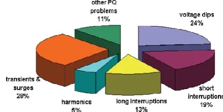
1. Power Quality Problems
swells, sparkles, harmonic distortions, impulse transients, flicker and interruptions.
Figure 1. Power Quality Problems in Percentage
2. DVR
Dynamic voltage restoration (DVR) is a way of compensating voltage sags that occur in electric power distribution system. These sags caused by faults and overloading consume power and it decrease the performance of a power devices. DVR saves power via voltage injections which can affect the phase and wave-shape of the energy being provided devices for DVR consist of static variable devices, which are series compensation equipments that use voltage source converters (VSC). The fundamental principle of the dynamic voltage restorer is to inject a voltage of required value and frequency, so that it can restore the load side voltage to the favourable amplitude and waveform even when the supply voltage is unbalanced or distorted. Commonly, it employs a gate turn off thyristors (GTO) stable power digital switches in a pulse width modulated (PWM) inverter structure. The DVR can generate or take in independently controllable real and reactive energy at the load side. In different phrases, the DVR is fabricated from a strong nation DC-AC switching electricity converter that injects three segment AC output voltages in series and in synchronism with the distribution and transmission line voltages.
3. Components of DVR
The power circuit of DVR includes following principal five elements: Voltage supply inverter (VSI), Voltage injection booster transformer, DC electricity storage
Device, low bypass harmonic filter and a as shown in Figure 2.
Figure 2. Components of DVR
A. Injection/Booster Transformer
Its primary characteristic is to step up the ac low voltage supplied by the VSI to the specified voltage. It is custom made designed transformer that attempts to restriction the coupling of noise and transient strength from the primary side to secondary. It connects the DVR to the distribution network through the HV windings. In addition to this, it also provides the isolation of the load from the system. In case of 3 ph DVR, three single phase injection transformers are used.
B. Passive Filter
A passive low pass filter consists of inductors and capacitors. it can be placed either at HV side or the inverter side of the injection/booster transformer. It is used to clear out the switching harmonic components from the injected voltage . By placing the passive filter at the inverter side , the higher order harmonics are avoided from penetrating into the transformer. When the filter is placed at the HV side , the harmonics can penetrate into the excessive HV side of the transformer , a high rating is required.Filter has a small score approximately 2% of the burden MVA related to delta-connected tertiary winding of the injection transformer.
C. Voltage Source Inverter
system. The inverter switches are commonly fired by using of a sinusoidal Pulse Width Modulation (PWM) Technique. The PWM generates sinusoidal signals through evaluating a sinusoidal wave with a saw spike wave and sending appropriate alerts to the inverter switches. Generally the score of VSI is low voltage and high current because of the usage of step up injection transformers.
D. DC Energy Storage Device
The main function is to deliver the vital energy to the VSI through a dc link for the generation of injected voltages. The various forms of strength storage gadgets are superconductive magnetic energy storage (SMES), batteries, fly wheels, supercapacitors and capacitors. The capacity of the saved power at once determines the duration of the sag which may be mitigating by using the DVR. Batteries are the not unusual choice and can be relatively powerful if a HV configuration is used. This HV string of batteries may be placed across the regulated dc bus with few or no extra circuitry. For Batteries and SMES, DC-AC conversion (inverters) is necessary, wheareas for flywheels AC to AC conversion required
4. DVR Equation
Figure 3. Equivalent Circuit diagram of DVR
The system impedance Zth depends on the fault level of
the load bus. When the system voltage (Vth) drops, the
DVR injects a series voltage VDVR through the injection
transformer so that the desired load voltage magnitudeVL can be maintained. The series injected voltage of the DVR can be written as
= - +
Where
: The magnitude of voltage across the load : The load impedance.
: The load current
: The system voltage during fault.
The Load current IL is given by
IL=(PL+jQL)/V
Taking VL as a reference the equation can be written as
α,β and δ are the corresponding angles of VDVR,ZTH,VTH
respectively and θ is the load angle. θ= tan-1(Q
L/PL)
The complex power injected by DVR is given by SDVR=VDVR×IL*
5. VI. Voltage injection methods of DVR
Voltage injection techniques of a DVR depend on the limiting elements such as; DVR power ratings, diverse situations of load, and distinctive kinds of voltage sags. Sensetive loads towards phase angel jump and some are sensitive in the direction or change in magnitude and others are tolerant to these. Thus the compensation techniques totally deponds upon the type of load.
There are four different methods of DVR voltage injection which are as follows:
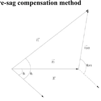
A. Pre-sag compensation method
The pre-sag technique monitors the supply voltage constantly and if it detects any disturbances in supply voltage it will inject the difference voltage among the sag or voltage at the point of common coupling and pre-fault situation, in order that the load voltage can be restored to the pre-fault condition. Compensation of voltage sags in the both phase angle and magnitude sensitive hundreds might be completed by using pre-sag compensation technique. In this method the injected active power cannot be controlled and it is decided by external conditions which include such type of faults and overload situations
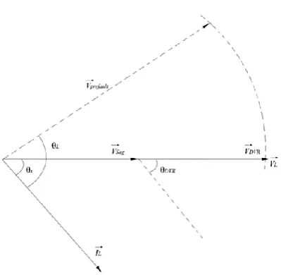
B. In-phase compensation method
Figure 5. Sag Compensation During Fault
In this technique the injected voltage is in phase with the supply side voltage regardless of the load current and prefault voltage. The phase angles of the presag and load voltage are different however the most significant criteria for power quality that is the constant magnitude of load voltage are satisfied. One of the advantage of this method is that the amplitude of DVR injection voltage is minimum for a certain voltage sag in evaluation with other strategies. Practical application of this technique is in non-sensitive loads to the jump in phase angle.
C. In-phase advanced compensation
method(IPAC)
In this method the real power spent through the DVR is reduced by minimizing the power angle δ between the sag voltage and load current. In case of pre-sag and in-phase compensation technique the active power is injected into the system all through disturbances. The active power supply is limited stored power in the DC links and this element is one of the maximum-priced parts of DVR. The minimization of injected power is finished by making the active power component zero by making the injection voltage phasor perpendicular to load current phasor.
In this method the values of load current and voltage are fixed in the system so we can change the phase of the sag voltage. IPAC technique uses only reactive power and unfortunately, not al1 the sags may be mitigated with out real power, accordingly, this approach is suitable for a limited range of sags.
D. Voltage tolerance method with minimum
energy injection
Figure 6. Sag compensation with minimum energy
III.
RESULTS AND DISCUSSION
Simulation on MATLAB
A. Parameters for system without DVR
Table 1. Parameters for system without DVR.
B. Parameters of System with DVR
Table 2. Parameter of System with DVR.
C. Power System without DVR
Single line diagram of the power system which is used to evaluate the performance of the proposed DVR control system under different fault scenarios, using the MATLAB/SIMULINK software. In this paper, two different types of loads are considered. One is the resistive-inductive (R-L) loads sudden change in load is one of the reasons of voltage sag/swell. The second one is sensitive loads which are adversely affected by voltage sags
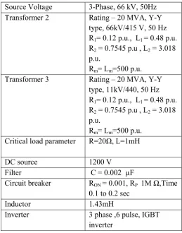
Figure 7. System without DVR Source Voltage 3-Phase, 11 kV, 50Hz
Line Inductance Line Resistance
1.33µH 0.001Ω
Transformer 1 Rating – 20 MVA, Y/∆/ ∆ type, 11 kV/66kV/66kV, 50 Hz
R1 = 0.002 p.u , L1= 0.08
p.u.
R2 = 0.12 p.u. , L2 = 0.48 p.u.
Rm = Lm = 800 p.u.
Transformer 2 Rating – 20 MVA, Y-Y type, 66kV/11 KV, 50 Hz
R1= 0.12 p.u., L1 = 0.48 p.u.
R2 = 0.7545 p.u , L2 = 3.018
p.u.
Rm= Lm=500 p.u.
Transformer 3 Rating – 20 MVA, Y-Y type, 11kV/440, 50 Hz
R1= 0.12 p.u., L1 = 0.48 p.u.
R2 = 0.7545 p.u , L2 = 3.018
p.u.
Rm= Lm=500 p.u.
Source Voltage 3-Phase, 66 kV, 50Hz Line Inductance
Line Resistance
1.33µH 0.001Ω
Transformer 1 Rating – 20 MVA, Y/∆/ ∆ type, 11 kV/66kV/66kV, 50 Hz
R1 = 0.002 p.u , L1= 0.08
p.u.
R2 = 0.12 p.u. , L2 = 0.48 p.u.
Rm = Lm = 800 p.u.
Source Voltage 3-Phase, 66 kV, 50Hz Transformer 2 Rating – 20 MVA, Y-Y
type, 66kV/415 V, 50 Hz R1= 0.12 p.u., L1 = 0.48 p.u.
R2 = 0.7545 p.u , L2 = 3.018
p.u.
Rm= Lm=500 p.u.
Transformer 3 Rating – 20 MVA, Y-Y type, 11kV/440, 50 Hz R1= 0.12 p.u., L1 = 0.48 p.u.
R2 = 0.7545 p.u , L2 = 3.018
p.u.
Rm= Lm=500 p.u.
Critical load parameter R=20Ω, L=1mH
DC source 1200 V
Filter C = 0.002 µF
Circuit breaker RON = 0.001, RP 1M Ω,Time
0.1 to 0.2 sec
Inductor 1.43mH
Inverter 3 phase ,6 pulse, IGBT
Above figure shows Single line diagram of power system feeding two parallel lines. The fault is occurring in second line for duration 0.1 to 0.2 second. All data taken for simulation are mentioned in table6.1
Figure 8. Voltage waveform
D. Power system with 3 phase fault.
This is the second test system for DVR is composed by a 13 kV, 50 Hz Generation system, feeding transmission line through a 3-winding transformer connected in Y/Δ,13/115KV/115KV. Such transmission line feed distribution network through step down transformer connected in Δ/Y, 115/11 kV. To verify the working of DVR for voltage compensation a fault is applied at point X at resistance 5 ohm for time duration of 0.1 s.
Figure 8. Power system with 3 phase fault
Figure 6.4.2 Simulation result of voltage waveform
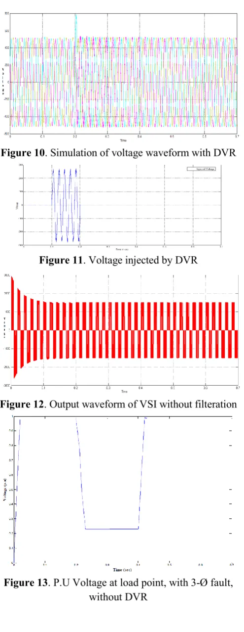
E. Power system with DVR
This is the third test system for DVR is composed by a 13 kV, 50 Hz Generation system, feeding transmission line through a 3- winding transformer connected in Y/Δ,13/115KV/115KV. Such transmission line feed distribution network through step down transformer connected in Δ/Y, 115/11 kV. To verify the working of DVR for voltage compensation a fault is applied at point X at resistance 0.066 ohm for time duration of 0.1 s. The DVR is simulated to be in operation only for the duration of the fault.
Figure 10. Simulation of voltage waveform with DVR
Figure 11. Voltage injected by DVR
Figure 12. Output waveform of VSI without filteration
Figure 13. P.U Voltage at load point, with 3-Ø fault, without DVR
Figure 14. P.U Voltage at load point, with 3-Ø fault, with DVR
IV.
CONCLUSION
The DVR with the proposed controller can improve the Voltage profile of the power system during different kinds of disturbances. A DVR model will develop with all the necessary components and controllers in order to demonstrate its effectiveness in maintaining a fast voltage regulation at any bus bar. By simulation process under the MATLAB (Simulink) environment, a DVR will be modelled efficiently. Voltage sag has been simulated by the application of a sudden load in the existing feeder. The sag so generated has been compensated using the modelled DVR .But more efficient results are expected with use of PWM inverter and PI controller for control purpose.
V.
REFERENCES
[1]. RavillaMadhusudanl, Student Member, IEEE, and
G. RamamohanRao "Modeling and Simulation of a Dynamic Voltage Restorer (DVR) for Power Quality Problems Voltage Sags and Swells” IEEE- International Conference On Advances In Engineering, Science And Management (ICAESM -2012) March 30, 31,2012.
[2]. 2Shabnam Rukhsar and Dr. D.P. Kuthari
"Application of DVR for Power Quality Improvement” International Research Journal of Engineering and Technology (IRJET) Volume: 02 Issue: 03 June-2015.
[3]. R V D Rama Rao, 2Dr.Subhransu Sekhar Dash,
VOLTAGE RESTORER USING HYSTERESIS BAND VOLTAGE CONTROL Journal of Electrical Engineering
[4]. ManishaUddhavDaund ,Prof. PankajGautam and
Prof.A.M.Jain EXPLORATION OF VOLTAGE SAG AND ITS MITIGATION TECHNIQUES International Conference on Electrical, Electronics, and Optimization Techniques (ICEEOT) – 2016.
[5]. T AppalaNaidu "The Role Of Dynamic Voltage
Restorer(DVR) in Improving Power Quality” International Conference on Advances in Electrical, Electronics, Information, Communication and Bio-Informatics (AEEICB16)
[6]. Shweta Singh, VivekanandRai, Awadhesh Kumar
and KishanBhusanSahay "Simulation and
Comparison of DVR and D-STATCOM for Voltage Sag Mitigation”
[7]. Ansal, K. Ravikumar, P.ParthibanTransformerless
Dynamic Voltage Restorer for Voltage Sag Mitigation 2016 Biennial International Conference on Power and Energy Systems:Towards Sustainable Energy (PESTSE)
[8]. N.H. Woodley, Senior Member, IEEEPittsburgh,
PA 15235 USA L. Morgan, Member, IEEE A. Sundaram, Member, Experience With An Inverter-BasedDynamic Voltage Restorer lEEETransactions on Power Delivery, Vol. 14, No. 3, July 1999.
[9]. RavillaMadhusudan‘Modeling and Simulation of a
Dynamic Voltage Restorer (DVR) for Power Quality ProblemsVoltage Sags and Swells’ IEEE- International Conference On Advances In Engineering, Science And Management (ICAESM -2012) March 30, 31,2012.
[10]. Reza Sedaghati1, Mehdi Ghasemi2 and Mahdi
Hayatdavudi3 "Performance Study of Dynamic Voltage Restorer (DVR) in order to Power Quality Improvement
[11]. A. A. D. RanjithPerera, and S. S. Choi Performance
Improvement of the Dynamic Voltage Restorer With Closed-Loop Load Voltage and Current-Mode Control MahindaVilathgamuwa, Senior Member, IEEE, , Member, IEEE2002.
[12]. H.P. Tiwari and Sunil Kumar Gupta International
Journal of Innovation, Management and
Technology, Vol. 1, No. 3, August 2010 ISSN: 2010-0248 "Dynamic Voltage Restorer against Voltage Sag” 2010.
[13]. K. VenkateswararaoInternational Electrical
Engineering Journal (IEEJ) Vol. 3 (2012) No. 2, pp. 745-750 ISSN 2078-2365 Page 745 Pudiet. al., Power Quality Enhancement using Custom Power Devices Power Quality Enhancement using Custom Power Devices PudiSekhar 2012.
[14]. Keith Corzine, VahidDargahiMedium Voltage
Dynamic Voltage Restorer (DVR) Based on DFCM Converter for Power Quality Improvement Vahid Dargahi1, Student Member, IEEE, ArashKhoshkbar Sadigh2, Member, IEEE, and Keith Corzine1, Senior Member, IEEE 1 Microgrid and Power Electronics Laboratory, Holcombe Department of Electrical and Computer Engineering, Clemson University, Clemson, SC 29634, USA.
[15]. S.DeepikaM.SaranyaV.Poorani2015 International
Conference on Advanced Computing and Communication Systems (ICACCS -2015), Jan. 05 – 07, 2015, Coimbatore, INDIA PI CONTROLLER BASED DYNAMIC SAG COMPENSATOR WITH PV PANEL S.DeepikaM.SaranyaV.Poorani Assistant professor, EIE SNS College of Technology SNS College of Technology SNS College of Technology Coimbatore, India 2015.
[16]. Mohammed Abdul Ahad2016 Biennial
International Conference on Power and Energy Systems:Towards Sustainable Energy (PESTS E)Performance Analysis of DVR, DSTATCOM andUPQC For Improving The Power Quality WithVarious Control StrategiesMohammed Abdul
Ahad YahiyaDept. of Electrical and
ElectronicsUnder Graduate, JNTU Hyderabad, India2016.
[17]. N.G.Hingorani and L.Gyugyi (1999),