Abstract
Haptic devices have been applied in interactive operation to perform contact tasks. To explore the haptic perception characteristics of typical push-pull and rotation operation, an experimental system was built by incorporating a three degrees of freedom (3-DOF) haptic device and the virtual environment. In this system, the haptic device is used to provide motion commands to control the avatar in the virtual environment and to exert haptic feedback on the human operator generated by three motors. In order to evaluate the main influential factors of interactive system based on haptic devices, ergonomic assessments are designed and experimentally implemented. Preliminary studies on the factors including restoring force, guidance force, speed of the virtual avatar, and the arm length have been conducted. The results are of great significance for the design of a haptic device and haptic interaction system by analyzing the specific requirements of ergonomics.
Keywords:Haptic device, Haptic feedback, Interactive operation, Ergonomics assessments
1 Introduction
The development of many applications of interactive oper-ation requires flexible haptic master to perform contact tasks. These tasks include interaction with computer-aided design models, telerobotic surgery, micro/nano-manipula-tion, undersea salvage, and space telerobotic exploration and maintenance, decontamination, and decommissioning of chemical and nuclear facilities [1,2].
The execution of these tasks by a human operator is affected by his/her level of perception of the interaction objects [3]. This perception can be enhanced by audio, visual, and haptic cues. While visual cues are certainly mandatory and audio cues beneficial at times, haptic cues can significantly improve the flow of information from the environment to the human operator for many tasks requiring dexterity [4]. Haptic devices are the most popular devices to provide haptic feedback in interactive manipulations. As a medium between environments and human users, haptic interfaces transmit and display hap-tic stimuli [5]. With precisely controlled forces and tor-ques exerted on the manipulator’s fingertips, hand, or arm, subtle sensations are able to be perceived, thus a high level of immersion is constructed. In the past
decades, several types of haptic master devices featuring the feedback function have been proposed, some of which are commercially available devices and some are
experimental prototypes [6, 7]. The PHANToM, which
is the most commonly used haptic device, can generate force feedback along six degrees of freedom (6-DOF)
motions using motors [8]. The Xitack IHP of Xitack
SA, which has been proposed for virtual reality applica-tions, has 4-DOF force feedback functions [9]. With the Dual ArmWork Platform (DAWP) at Argonne National
Laboratory [10], one of the key improvements the
Cobotic Hand Controller can provide to DAWP oper-ation is the implementoper-ation of virtual surfaces, or vir-tual constraints on motion, as suggested by Faulring [11]. Such haptic devices can reproduce the constraints or guidance and can vastly simplify execution of a con-tact task. While guidance or constraints can be imple-mented in the existing system, an active haptic device allows for the reproduction of these guidance or con-straints for the human operator and may reduce opera-tor’s fatigue while increasing efficiency by eliminating unneeded or wrong motions in workspace. Large im-provements on existing devices can only be achieved by a proper match between the performance of the device and human haptic abilities. To find out how the users can complete the operation with a haptic device by * Correspondence:[email protected];[email protected]
School of Instrument Science and Engineering, Southeast University, Nanjing 210096, China
creating synthetic haptic experiences, quantitative hu-man studies should be carried out. To determine the nature of these approximations, or, in other words, to find out what we can get away with in creating syn-thetic haptic experiences, ergonomics studies are essen-tial. Understanding of such influencing factors as the guidance force, the reset force, the speed of the virtual avatar, and the arm length is critical for proper design specification of the hardware and software of haptic interfaces.
Current trend in design of haptic masters is to meet the need for designs with safety, high performance, suf-ficient workspace, enough force and torque, high stiff-ness, and small inertia [12–14]. By their nature, haptic devices operate in contact with a human operator.
Greater research effort on the operator’s perception
and overall performance using the haptic devices could accelerate the development of haptic interaction tech-nology [15–17]. In these researches, the haptic percep-tion of the users was optimized and evaluated using haptic devices. Human factors as well as others that affect the design specifications of force-reflecting haptic interfaces were also of a concern [18].
In this paper, we introduced a novel three degrees of freedom (3-DOF) haptic device. Concerned with quanti-tative measures of influencing factors that affect the overall performance, the design specifications of haptic interaction system are presented. The remainder of the paper is organized as follows. Mechanical design and kinematical analysis of the haptic device are presented in Section 2. Construction of a haptic interaction sys-tem based on the proposed haptic device is presented
in Section 3. Experimental method and construction
are presented in Section 4, and the performance of the
proposed system is verified experimentally in Section5. The paper is then concluded in Section6.
2 Three DOF haptic device 2.1 Mechanical design
Mechanical design of haptic devices is to meet the need for designs with sufficient workspace, enough force and
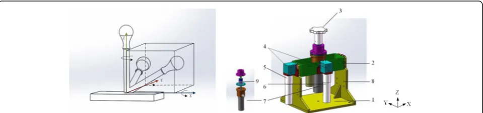
torque, high stiffness, small inertia, and mechanical de-coupling. However, some of these requirements, such as large stiffness and small inertia, are conflicting in nature [19,20]. Due to the multi-criteria and multi-domain func-tional and performance requirements of high-performing haptic devices, it is not sufficient to develop such a device by sub-optimizing the requirements from each separate discipline. The main design objectives of our device are to obtain a large workspace and mechanical decoupling and, at the same time, provide enough torque feedback. A parallel haptic device for interactive operation is de-signed which mainly consists of three mutually orthog-onal translatiorthog-onal axes that have lower inertia and better stiffness. The assembly drawing of this device is presented in Fig.1.
The haptic device mainly consists of the base, the cuboid frame and cylindrical sleeve, the handle, three actuators, and photoelectric encoders. The proposed structure is similar to a three-axis gyroscope in which three axes are orthogonal and intersect at a fixed point (coordinate origin). The cuboid frame is mounted hori-zontally on the base and can be rotated around theX-axis. The cylindrical sleeve is mounted vertically to be rotated around theY-axis. The handle is mounted coaxial with the
Z-axis actuator in the cylindrical sleeve and can be rotated around theZ-axis. In this way, each kinematic freedom is independent and there is no motion interference which means kinematic coupling is mechanically avoided.
While haptic devices usually work at a low speed and provide high torque, corresponding reducers are equipped to increase the output torque and to reduce the rotational speed. Three DC motors manufactured by Maxon Corporation are used to generate the force/ torque feedback. The device is capable of rendering con-tinuous forces up to 25 N in theX-andY-axes and torque of 0.5 Nm around theZ-axis.
2.2 Kinematics analysis
The kinematic diagram of the designed haptic device is described in Fig.2. The motion of the haptic device to any point in the workspace can be decomposed into
motion components on x-o-z plane and y-o-z plane respectively.
Assuming that the length of the handle bar is l(from
the intersection point to the end of the handle), the rota-tion angle around the Z-axis is θ3, and the rotation
an-gles on the x-o-z plane and y-o-z plane are θ1 and θ2
respectively, the coordinate of the end of the handle isP (Px, Py, Pz), then the relationship between the coordin-ate of the endP, the length of the handle bar l, and the rotation angles of the handle is (ignoring minor deform-ation of the bar),
Px¼ ffiffiffiffiffiffiffiffiffiffiffiffiffiffiffiffiffiffiffiffiffiffiffiffiffiffiffiffiffiffiffiffiffiffiffiffiffiffiffiffiffiffiffiffiffiffiffiffiffiffiffil tanθ1
1þðtanθ1Þ2þðtanθ2Þ2
q ð1Þ
Py¼ ffiffiffiffiffiffiffiffiffiffiffiffiffiffiffiffiffiffiffiffiffiffiffiffiffiffiffiffiffiffiffiffiffiffiffiffiffiffiffiffiffiffiffiffiffiffiffiffiffiffiffil tanθ2 1þðtanθ1Þ2þðtanθ2Þ2
q ð2Þ
Pz¼ ffiffiffiffiffiffiffiffiffiffiffiffiffiffiffiffiffiffiffiffiffiffiffiffiffiffiffiffiffiffiffiffiffiffiffiffiffiffiffiffiffiffiffiffiffiffiffiffiffiffiffil
1þðtanθ1Þ2þðtanθ2Þ2
q ð3Þ
θ3¼θ3 ð4Þ
The rotational ranges of the haptic device about the
X-,Y-, Z-axes are designed as−60°~60°, −60°~ 60°, and
−90°~ 90° respectively and the distance from the center of rotation to the end of the handle is 150 mm, so the motion space of the haptic device can be deduced to be
a spherical surface from formula (1–3) and its
work-space is up to 259.72 mm × 259.72 mm × 93.30 mm, as is drawn in Matlab as Fig.3.
3 Method and construction
3.1 Force-feedback system based on a haptic device The system consists of the human operator, the haptic device, the virtual environment which integrates with the graphical refresh model, the sampler, the virtual controller,
the force rendering module, and the motion capture/force
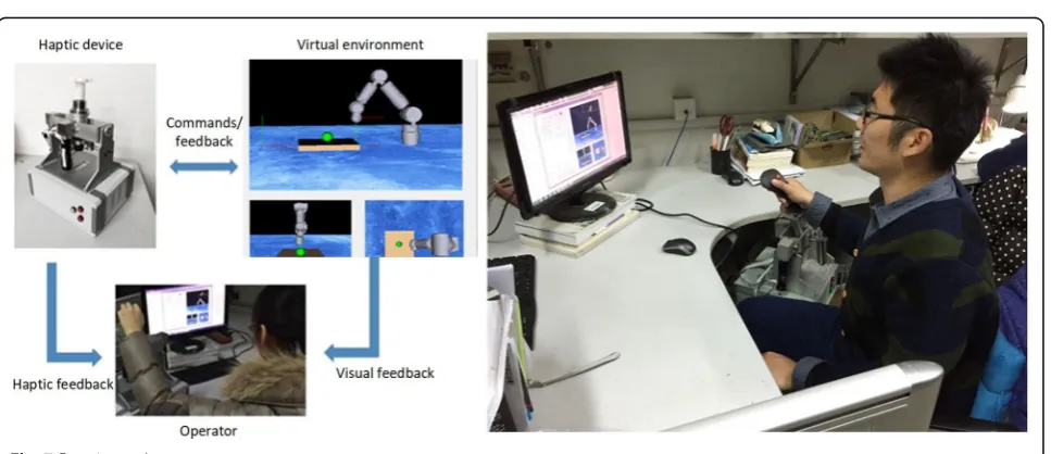
output model. Figure 4 shows the schematic diagram of
the system. In this system, the haptic device is utilized to acquire the motion of the operator’s hand to control the avatar in VR (virtual reality) and to provide force feedback to the operator so that he/she can feel the interactive force between the avatar and the virtual objects. The virtual en-vironment is used to create a digital model of the physical world in the computer. The goal of force rendering is to calculate the virtual force based on the kinematics and dy-namics model of different tasks and to convert the calcu-lated virtual forces to match the capabilities with the haptic device for stable force feedback. The motion cap-ture and force output model is to acquire the motion command (xm) and output the virtual force (fv) when a human operator operates the haptic device. The virtual controller is to program and control the avatar according to a predefined algorithm. The sampler model is to sample the pose of the avatar and the virtual objects, and the graphical refresh model is to renew the geometric model of the virtual environment which is shown to the human operator.
One of the major goals in this system is to provide the operator with force and visual feedback. The graphic model maintains the information about the geometric states of the avatar and the environment. Collision detec-tion is conducted while performing tasks in the virtual Fig. 2Kinematical diagram of the designed haptic device
Fig. 3Working space of the developed haptic device
environment. This allows the virtual objects to deform and give counterforce to the avatar. This force generated in the virtual environment exerts on the operator at the same time. Then the operator holding the haptic device feels the counterforce acting on the avatar and watches the motion of the virtual objects on the screen. The com-bination of visual and force feedback makes the operator feel the interaction of the virtual objects.
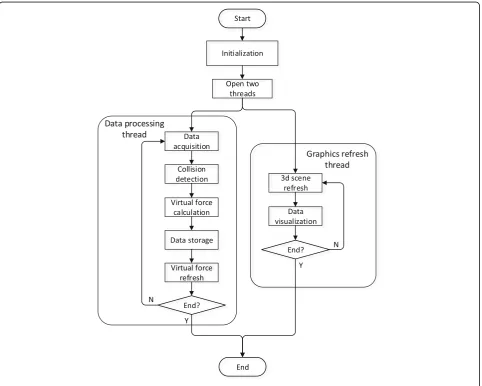
In order to improve the frequency of force feedback, the virtual environment module is divided into two loops, one is for visual display and the other is for force feedback. Since the two loops can be processed inde-pendently, the virtual force can be rendered at a high frequency of 500~1 kHz to ensure the continuity and stable perception for the human operator. The graphics refresh loop is to complete the collision detection and the collision response (including deformation calcula-tion and graphics rendering) at a lower frequency of tens of hertz.
3.2 Software design
The whole software is developed in Microsoft Visual Studio2008 platform, based on MFC (Microsoft Foun-dation Class) framework and Measurement Studio. OpenGL (Open Graphics Library) is used as a graphical interface to render the 3D virtual scene and to complete the dynamic element loading. The overall flowchart of the software is shown in Fig.5.
There are several different functional areas in the soft-ware interface. According to the function of each mod-ule of the force feedback system, the layout of the whole software is designed in detail. The first is the serial mode setting area. Before opening the serial port, the operator needs to set the serial port parameters by pulling down the menu on the serial port baud rate and serial number to choose to improve the software versatility and com-patibility. The second is data storage area which includes the rotation angles about each axis, the location and speed of the virtual avatar, and the feedback force information of
Fig. 6Software interface of the force feedback system
each degree of freedom. The third is data visualization area. In order to understand the feedback information in real time intuitively, the operator can click the monitor button to pop up a new window to display the three de-grees of freedom and virtual force feedback in dials and
waveforms. The fourth is virtual scene selection area. Three different virtual environments are designed in the software, namely the flexible ball scene model, virtual ro-botic task scene, and ball tracking scene. The operator can switch according to their own needs to operate in the Fig. 8Experimental tasks.aVirtual robotic scenario.bBall tracking scenario
corresponding scenario. The last is operation mode selec-tion area. The haptic device can be used for posiselec-tion con-trol or speed concon-trol. The operator can quickly switch between the position control mode and the speed control mode in this area. The overall software interface is shown in Fig.6.
fort and efficiency, so understanding of the operator’s op-erating habits is necessary to design a haptic device that is efficient, comfortable, and in line with people’s operating habits. In order to experimentally evaluate the influence of the design parameters, we built a prototype of VR-based haptic interaction system. Several ergonomic experiments are designed and performed. Effective data collected is uti-lized to statistically analyze the characteristics and effi-ciency while operating with the developed haptic device.
The experimental system consists of the developed haptic device, the virtual environment, and the operator, as shown in Fig. 7. The operator can control the avatar and sense the force feedback of the virtual environment, 6 28.394 28.200 25.624 55.664 52.983 52.648
7 23.462 21.954 18.694 53.469 52.694 48.691
8 23.489 20.645 19.369 49.648 44.669 45.893
9 19.762 19.239 17.425 51.673 50.945 50.694
10 21.694 20.469 20.964 55.644 52.469 50.442
Table 2Analysis of variance the maximum operating angle in six movement directions
Sum of the squares df Mean square F Significance
X+ (°)
Inter-group 279.912 2 139.956 4.651 0.018
Intra-group 812.525 27 30.094
Sum 1092.437 29
X−(°)
Inter-group 526.287 2 263.144 6.465 0.005
Intra-group 1099.021 27 40.704
Sum 1625.308 29
Y+ (°)
Inter-group 473.750 2 236.875 10.219 0.000
Intra-group 625.872 27 23.180
Sum 1099.622 29
Y−(°)
Inter-group 836.978 2 418.489 5.376 0.011
Intra-group 2101.904 27 77.848
Sum 2938.882 29
Z+ (°)
Inter-group 1769.057 2 884.528 6.194 0.006
Intra-group 3855.782 27 142.807
Sum 5624.839 29
Z−(°)
Inter-group 1160.788 2 580.394 2.300 0.120
Intra-group 6814.036 27 252.372
Sum 7974.824 29
such as contact force, frictional force, and guidance force, through the haptic device.
4.2 Experimental tasks
In this study, we mainly analyze several factors which play a significant role in the haptic interaction system, including the guidance force, the restoration force, the operating speed, and the arm length. Ten healthy volun-teers aged 20–30 years (habitual use of the right hand) participated in the experiments. The experiments consist of two parts. The first part is the virtual robotic task sce-nario shown as Fig.8awhich is designed to test the typ-ical operation of grasping and releasing. In this task scenario, the operator should control the virtual arm through the haptic device to grasp the green ball on the yellow plane, then move it to the red ball and release. Catching or releasing the ball is switched by the button
on the handle of the haptic device. In this experiment, no guidance is provided and the operator should plan their own path according to the information available. The second part is a ball tracking scenario shown in Fig.9bwhich is designed to test the typical operation of trajectory tracking. This is a path-guided operational task. The operator should control the blue ball through the haptic device to track the pink ball following the preset path. Once the blue ball touched the pink ball, the latter moved to the next positon and the operator should go on tracking. The entire process consists of six such cycles.
A variable-controlling approach is applied in the ex-periment to analyze the effects of each factor on the interactive operation. The first factor is the guidance force (fg) provided by the motors to guide the operator to move toward the target. Suppose the guidance force
a
b
c
d
e
f
of 0 N, 2 N, and 4 N is for conditions a1, a2, and a3 re-spectively. The second factor is the restoration force (fr) exerted by the motors which drives the haptic device back to the originating pose after operating or in the non-operating state. Suppose the restoration force of 0 N, 2 N, and 4 N is for conditions b1, b2, and b3 re-spectively. The third is the speed of the virtual avatar which is set at 0.5 cm/s, 1.5 cm/s, and 2.5 cm/s for con-ditions c1, c2, and c3 respectively.
Among all these control factors, a1, b1, and c2 are the default control factors. During the experiments, when the influence of a variable is studied, the con-trol factor of this variable is changed, and other vari-ables are the default factors. For example, three groups of experiments under conditions of a1 × b1 × c2, a2 × b1 × c2, and a3 × b1 × c2 should be carried out to study the effect of the guidance force in the virtual robotic scenario and the ball tracking scenario
respectively. So each subject needs to do 18
experiments, and the experimental sequences of each subject were randomly arranged.
5 Results and analysis 5.1 Effects of the guidance force
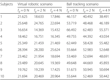
In order to investigate the influence of the guidance force on the operation efficiency of the interactive sys-tem, three levels of 0 N, 2 N, and 4 N were applied in the experiment. The average time for completing the de-signed task was recorded, as is shown in Table1.
According to the statistical data in Table 1, a task
completion time histogram of each operator with three levels of guidance force in two scenarios is shown in Fig.9.
As can be seen from Fig. 9, the overall distribution
of task completion time in three cases is consistent although the task completion time of ten subjects is slightly different. The guidance force will shorten the task completion time in both two scenarios. In the
a
b
c
d
e
f
case of the virtual robot scenario, task completion time was reduced by 15.3% at most and 8% on aver-age with 2 N guidance force compared with no guid-ance force. When 4 N guidguid-ance force was available, task completion time was shortened by 20.3% at most and 12.7% on average. In the ball tracking sce-nario, task completion time reduction was 10.77% at most and 6.7% on average with 2 N guidance force compared with no guidance force. When 4 N guide
force was available, task completion time was short-ened by 16.60% at most and 10.6% on average. The result indicates that the guidance force can give the operator helpful hint to improve the operation effi-ciency and to shorten the task completion time. Al-though task completion time is averagely shortened with 4 N guide force compared with 2 N guide force, further experiments should be carried out to study the optimal guidance force for different subjects and different tasks.
5.2 Relationship between the restoration force and the operating range
To study the effect of the restoration force on the haptic interactive operation, the restoration force was set at three grades that include elastic force of the rubber bands only, elastic force plus 2 N motor output, and elastic force plus 4 N motor output. Other variables were the default factor. Univariate
analysis of variance was used to analyze. Table 2
shows the result of variance analysis of the
Table 3Variance analysis of virtual avatar motion
Sum of the squares df Mean square F Significance
X+ (°)
Inter-group 199.247 2 99.624 4.004 0.030
Intra-group 671.833 27 24.883
Sum 871.080 29
X−(°)
Inter-group 250.083 2 125.041 2.350 0.115
Intra-group 1436.942 27 53.220
Sum 1687.025 29
Y+ (°)
Inter-group 124.523 2 62.261 2.013 0.153
Intra-group 835.071 27 30.929
Sum 959.593 29
Y−(°)
Inter-group 354.916 2 177.458 2.142 0.137
Intra-group 2236.635 27 82.838
Sum 2591.551 29
Z+ (°)
Inter-group 1412.462 2 706.231 4.761 0.017
Intra-group 4005.187 27 148.340
Sum 5417.648 29
Z−(°)
Inter-group 1083.262 2 541.631 1.721 0.198
Intra-group 8496.079 27 314.670
Sum 9579.341 29
Table 4Homogeneous test of variance under conditions of different avatar speeds
Levene statistic (°) df1 df2 Significance
X+ 1.019 2 27 0.375
X− 1.806 2 27 0.184
Y+ 0.985 2 27 0.386
Y− 2.259 2 27 0.124
Z+ 0.495 2 27 0.615
maximum operating angle (in degree) in three de-grees of freedom.
In the result of the variance analysis given in Table2,
the sum of the squared variance, the mean square, theF
value, and the probability P of the groups are given. It can be seen from the significance level P< 0.05 that
there was a significant difference in the mean value be-tween groups in the positive and negative directions of
the X- and Y-axes and the positive direction of the
Z-axis at the 0.05 level.
Figure 10 shows the histogram of the range of the
movement of the hand in the positive and negative
2.00 −2.01300 2.23082 0.375 −6.5903 2.5643
X−(°) 1.00 2.00 −3.68900 3.26252 0.268 −10.3831 3.0051
3.00 −7.07000 3.26252 0.039 −13.7641 −.3759
2.00 1.00 3.68900 3.26252 0.268 −3.0051 10.3831
3.00 −3.38100 3.26252 0.309 −10.0751 3.3131
3.00 1.00 7.07000 3.26252 0.039 .3759 13.7641
2.00 3.38100 3.26252 .309 −3.3131 10.0751
Y+ (°) 1.00 2.00 2.33300 2.48711 .357 −2.7701 7.4361
3.00 4.98700 2.48711 0.055 −.1161 10.0901
2.00 1.00 −2.33300 2.48711 0.357 −7.4361 2.7701
3.00 2.65400 2.48711 0.295 −2.4491 7.7571
3.00 1.00 −4.98700 2.48711 0.055 −10.0901 .1161
2.00 −2.65400 2.48711 0.295 −7.7571 2.4491
Y−(°) 1.00 2.00 −5.47200 4.07034 0.190 −13.8236 2.8796
3.00 −8.28400 4.07034 0.052 −16.6356 .0676
2.00 1.00 5.47200 4.07034 0.190 −2.8796 13.8236
3.00 −2.81200 4.07034 0.496 −11.1636 5.5396
3.00 1.00 8.28400 4.07034 0.052 −.0676 16.6356
2.00 2.81200 4.07034 0.496 −5.5396 11.1636
Z+ (°) 1.00 2.00 10.28330 5.44684 0.070 −.8927 21.4593
3.00 16.65510 5.44684 0.005 5.4791 27.8311
2.00 1.00 −10.28330 5.44684 0.070 −21.4593 .8927
3.00 6.37180 5.44684 0.252 −4.8042 17.5478
3.00 1.00 −16.65510 5.44684 0.005 −27.8311 −5.4791
2.00 −6.37180 5.44684 0.252 −17.5478 4.8042
Z−(°) 1.00 2.00 −8.10550 7.93309 0.316 −24.3829 8.1719
3.00 −14.69300 7.93309 0.075 −30.9704 1.5844
2.00 1.00 8.10550 7.93309 0.316 −8.1719 24.3829
3.00 −6.58750 7.93309 0.414 −22.8649 9.6899
3.00 1.00 14.69300 7.93309 0.075 −1.5844 30.9704
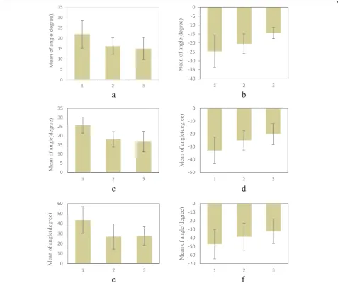
directions of the X, Y, and Z under the conditions of three grades of restoration force. The abscissa in
Fig. 11 is 1, 2, and 3, representing the motor
restor-ation force of 0 N, 2 N, and 4 N respectively and the vertical axis represents the maximum motion range in degree (°).
As can be seen from Fig.10, the restoration force has an important effect on the operating range of the haptic device in all directions. The greater the restoration force, the smaller the corresponding operating range. This is possibly because the restoration force constraints the free motion of the operator to some extent. So the res-toration force should be minimized in the condition that the restoration is ensured.
5.3 Relationship between the speed of the avatar and the operating range
In this experiment, the speed of the virtual avatar is set at 0.5 cm/s, 1.5 cm/s, and 2.5 cm/s respectively and the other factors are set as default factors. Three groups of the operable range were recorded in degree (°) and one-way analysis of variance (ANOVA) was used to study the effects of different conditions. The results are shown in Table3.
It can be seen from the significance level (P< 0.05)
that the intra-group means along X-axis positive
dir-ection and Z-axis positive direction are significantly
different (P< 0.05) while the differences in other di-rections are not significant. Furthermore, the differ-ences of the measurement data were compared with the homogeneity test of variances, and the results in-dicated there was no significant difference between
the variance of each group at the 0.05 level; that is,
the variance is homogeneous, as is shown in Table 4.
Least significant difference (LSD) multiple compari-son procedure was used for further analysis. In
Table 5, the experimental mean values were compared
while the avatar in VR moved at different speeds. When the significance level was less than 0.05, there was a significant difference between the two groups. The results show that there is a significant difference in operating range in the six directions when the vir-tual object moved at the lowest speed and the highest speed, which indicates that the speed of the virtual object has an effect on the amplitude of the haptic device.
Figure 11 shows the histogram of the operating
range of the haptic device in the positive and negative directions of X,Y, and Z-axis under the conditions of
three grades of avatar speed. The abscissa in Fig. 12
is 1, 2, and 3, representing the avatar speed of 0.5 cm/s, 1.5 cm/s, and 2.5 cm/s respectively. The vertical axis represents the maximum operating angle in degrees in the corresponding direction.
It can be seen from Fig.11that the moving speed of the virtual avatar has a certain influence on the operating range in each direction. The larger the moving speed, the smaller the operating range in the corresponding motion direction.
5.4 Relationship between the arm length and the operating range
In the experiment, the length of the right arm (the dis-tance from the scapula to the palm) of each subject was
measured. Figure 12 shows the scatter plot of the
rela-tionship between the operating range and the arm length. The abscissa is the arm length and the ordinate is the average operating range of multiple experiments.
Method of correlation analysis was applied to study the relevance. In this paper, the Spearman correlation coefficient was used to analyze the relationship between the arm length and the operating range. The results are shown in Table6.
From Table 6, the operating range correlates with the arm length in the X-axis andY-axis positive direction at the 0.05 significant level. Because theX-axis positive dir-ection is to move the handle of the haptic device to right and the Y-axis positive direction is to move forward, it can be deduced that the operating range and the arm Fig. 12The scatter plot of the relationship between the operating
range and the arm length
Table 6Operation space range and arm length correlation coefficient table
X+ (°) X−(°) Y+ (°) Y−(°) Z+ (°) Z−(°)
Spearman rank correlation coefficient
Arm length (cm) Correlation coefficient 0.638 −0.413 0.675 −0.122 0.626 0.371
Sig.(double sides) 0.047 0.235 0.032 0.783 0.053 0.291
length are positively correlated when the handle is moved away from the body and the correlation coeffi-cients are 0.638 and 0.655 respectively.
5.5 Differences in operating range along different directions
Table 7shows the operating ranges of the experimenter
in each direction in each experiment, i.e., the maximum operating angle.
As can be seen from Table 7, the maximum range
along X and Y negative direction is greater than that
along the positive direction. X negative direction repre-sents moving the handle to the left and positive direc-tion represents moving the handle to the right. Similarly,
Ynegative direction represents moving the handle close
to the operator and the positive direction represents moving the handle away from the operator. It can be concluded that the motion of the operator’s handle to-ward himself/herself is greater than moving away from himself/herself. This means that asymmetric control interval is necessary for a haptic device-based system.
5.6 Determination of operating range and operation speed
Three sets of experiments were taken to study the oper-ating range of the haptic device while the moving speed
of the swing from left to right is about−11.49~10.33 cm, the magnitude of the swing forwards or backwards is
about −15.32~13.06 cm, and the wrist rotation angle
range is−41.60°~39.09°.
In the experiment, the speed at which the operator operates the handle is recorded at the same time, so the maximum operating speed of the operator can be
ob-tained by the above method. Table8shows the operating
speed of the subjects in each direction in experiments, in degrees per second.
Since the moving speed and the reset force of the virtual avatar have no significant effect on the operating speed, all the experimental results are averaged and the maximum operating speed in different directions can be obtained. The operating speed in theX,Y, andZ-axes is−109.18°/ s~98.38°/s, −99.73°/s~92.06°/s, −310.60°/s~300.75°/s re-spectively. Converted the speed to translation in the workspace, the operating speed from left to right is
−57.17~51.51 cm/s, the operating speed forwards
and backwards is −52.22~48.20 cm/s. That is, the
operators are used to operating the haptic device at such speed and this should be considered while an interactive system is designed using a haptic device.
Ergonomics is actually the study of the relationship between people, machines, and the environment, aim-ing at safety, health, comfort, and efficiency opti-mization. The research content can be the study on human factors, the optimization of the human-machine system design, improvements of operations, analysis of the environment, and so on. As for the haptic Fast 16.194 −20.453 18.010 −25.108 27.031 −38.595
Large 15.013 −14.405 16.755 −20.160 27.707 −32.169
Table 8Operation speed data statistics
Direction X+ (°/s) X−(°/s) Y+ (°/s) Y−(°/s) Z+ (°/s) Z−(°/s)
Class
Speed of virtual object
Slow 102.333 −111.000 101.999 −103.666 381.943 −347.221
Medium 83.333 −113.333 76.333 −100.333 280.555 −305.555
Fast 89.524 −108.095 71.428 −76.666 255.952 −259.920
Reset force
Small 99.333 −101.666 104.332 −101.999 387.499 −348.610
Fast 98.000 −106.333 90.333 −112.333 255.555 −312.500
interaction system, not only precise measurement and reliable force feedback but also ergonomics research is
required to adapt to the operator’s physiology and
psychology. Ergonomic experiments and assessments are important to choose proper parameters in designing a comfort and efficient haptic device and the inter-action system.
6 Conclusions
In this study, a 3-DOF haptic device was designed to provide three DOF force feedback to human operators. VR-based interactive system using the developed device was built and ergonomic experiments were conducted. The effective data collected by the force feedback handle system was used for statistical analysis. The characteris-tic efficiency and workspace were mainly analyzed. Stat-istical analysis was used to study the influencing factor including the guiding force, the reset force, the speed of the virtual object, and the arm length. The experimental results can provide evidence for how to design and optimize the haptic device and the haptic interactive sys-tem. Besides the factors explored in this research,
hu-man factors such as the huhu-man operator’s character,
proficiency, perceptual and behavior habits, and the mechanical factor such as the shape of the handle and the size of the haptic device will also influence the haptic interaction. These factors would be explored further.
Abbreviations
DOF:Degrees of freedom; LSD: Least significant difference; MFC: Microsoft Foundation Class; OpenGL: Open Graphics Library; VR: Virtual reality
Acknowledgements
The authors thank the editor and anonymous reviewers for their helpful comments and valuable suggestions.
Funding
This paper is supported by the National Key Research and Development Program of China (No. 2016YFB1001301), NSFC 61673114 and Shanghai Aerospace Science and Technology Innovation Fund SAST2017-021.
Availability of data and materials
We can provide the data.
Authors’contributions
All authors take part in the discussion of the work described in this paper. HL organized the research. AS and BL joined in the design of the haptic device and conducted calibration experiments. BX and HZ participated in the formulation of main design targets. This writing was finished by HL and supervised by AS. All authors approved the final version of this paper.
Authors’information
Hui-Jun Li received her B.S. degree in measurement and control in 1999, and M.S. degree in condensed matter physics in 2002 from Zhengzhou University, Zhengzhou, and Ph.D. degree in measurement and control from Southeast University, Nanjing, in 2005. She is currently an associate professor with the School of Instrument Science and Engineering, Southeast University, Nanjing. Her research interests are on teleoperation, space robot, and rehabilitation robot.
Ai-Guo Song received the B.S. degree in automatic control and the M.S. degree in measurement and control from the Nanjing University of Aeronautics and Astronautics, Nanjing, China, in 1990 and 1993, respectively, and the Ph.D.
degree in measurement and control from Southeast University, Nanjing, China, in 1996. From 1996 to 1998, he was an Associate Researcher with the Intelligent Information Processing Laboratory, Southeast University. From 1998 to 2000, he was an Associate Professor with the Department of Instrument Science and Engineering, Southeast University. From 2000 to 2003, he was the Director of the Robot Sensor and Control Laboratory, Southeast University. From April 2003 to April 2004, he was a Visiting Scientist with the Laboratory for Intelligent Mechanical Systems, Northwestern University, Evanston, IL, USA. He is currently a Professor with the School of Instrument Science and Engineering, Southeast University. His current interests include teleoperation, haptic display, Internet telerobotics, and distributed measurement systems.
Bo-Wei Li received her B.S. degree in measurement and control in 2013 from Nanjing University of Science and Technology and M.S. degree in condensed matter physics from Southeast University, Nanjing, in 2016. She is currently an engineer engaging in the development of human-machine interface and related algorithms.
Bao-Guo Xu received his B.S. degree in measurement and control from China University of Mine and Technology, Xuzhou, China, in 2004 and Ph.D. degree in measurement and control from Southeast University, Nanjing, China, in 2009. He is currently an Associate Professor in the School of Instrument Science and Engineering, Southeast University. His interests include brain computer interface and rehabilitation robot.
Hong Zeng received the Ph.D. degree in computer science from Hong Kong Baptist University, Hong Kong, in 2010. He is currently an Associate Professor with the State Key Laboratory of Bioelectronics, Robot Sensor and Control Laboratory, School of Instrument Science and Engineering, Southeast University, Nanjing, China. His current research interests include bioRobot/ bioMechatronic interfaces, haptic interaction systems and cortically coupled human-machine collaboration.
Ethics approval and consent to participate
Not applicable.
Consent for publication
Not applicable.
Competing interests
The authors declare that they have no competing interests.
Publisher’s Note
Springer Nature remains neutral with regard to jurisdictional claims in published maps and institutional affiliations.
Received: 15 July 2018 Accepted: 6 September 2018
References
1. A. Bolopion, S. Régnier, A review of haptic feedback teleoperation systems for micromanipulation and microassembly[J]. IEEE Trans. Autom. Sci. Eng.
10(3), 496–502 (2013)
2. T. Sasaki, K. Kokubo, H. Sakai, Hydraulically driven joint for a force feedback manipulator[J]. Precis. Eng.47, 445–451 (2017)
3. C. Pacchierotti, L. Meli, F. Chinello, et al., Cutaneous haptic feedback to ensure the stability of robotic teleoperation systems[J]. Int. J. Robot Res.
34(14), 1773–1787 (2015)
4. F. Oscari, R. Oboe, O.A. Daud Albasini, et al., Design and construction of a bilateral haptic system for the remote assessment of the stiffness and range of motion of the hand[J]. Sensors16(10), 1633 (2016)
5. Laycock S D, Day A M. Recent developments and applications of haptic devices[C], Computer Graphics Forum. Oxford: Blackwell Publishing, Inc, 2003, 22(2): 117–132.
6. D. Borro, J. Savall, A. Amundarain, et al., A large haptic device for aircraft engine maintainability [J]. IEEE Comput. Graph. Appl.24(6), 70–74 (2004) 7. R.J. Adams, M.R. Moreyra, B. Hannaford, inProc of the Asme Winter Annual
Meeting Haptics Symposium. Excalibur, a three-Axis force display[J] (2010) 8. M.C. Çavuşoğlu, D. Feygin, F. Tendick, A critical study of the mechanical and
Massachusetts, USA; 2015.
14. H. Qin, A. Song, Y. Liu, et al., Design and calibration of a new 6 DOF haptic device[J]. Sensors15(12), 31293–31313 (2015)
15. B. Sauvet, T. Laliberte, C. Gosselin, Design, analysis and experimental validation of an ungrounded haptic interface using a piezoelectric actuator[J]. Mechatronics45, 100–109 (2017)
16. I. Sarakoglou, N. Garcia-Hernandez, N.G. Tsagarakis, et al., A high performance tactile feedback display and its integration in teleoperation[J]. IEEE Trans. Haptics5(3), 252–263 (2012)
17. X. Sun, U. Sellgren, K. Andersson, Situated design optimization of haptic devices[J]. Procedia CIRP50, 293–298 (2016)
18. H.Z. Tan, M.A. Srinivasan, B. Eberman, et al., Human factors for the design of force-reflecting haptic interfaces[J]. Dyn. Syst. Control55(1), 353–359 (1994) 19. R. Ellis, O. Ismaeil, M. Lipsett, Design and evaluation of a high-performance
haptic interface. Robotica14, 321–327 (1996)