ISSN (e): 2250-3021, ISSN (p): 2278-8719
Vol. 09, Issue 5 (May. 2019), ||S (IV) || PP 47-55
Design Implementation of a Power Electronic Bidirectional
DC/DC converter Interface with Dual Battery Energy Storage for
Hybrid Electric Vehicle System using Fuzzy Controller
Miss. Vaishnavi S. Yadao
1, Prof. Nilesh Chamat
2, Prof. Piyush Bahad
3,
1(Department of Electrical Engineering, BIT, BALLARPUR, India) 2(Department of Electrical Engineering, BIT, BALLARPUR, India) 3
(Department of Electrical Engineering, JIT, RTMNU Nagpur, India)
Abstract:
Power Electronic Interface plays a very important role in clean vehicle technologies. This paper proposes a unique bidirectional dc-dc converter, which can interface main energy storage (ES1) and auxiliary energy storage (ES2), and also dc bus of different voltage levels for numerous applications in hybrid electric vehicle systems. This proposed topology is capable of delivering power from low voltage dual source to dc link i.e Powering mode known as Step Up mode and also delivering power from high voltage dc link to dual source i.e regenerating mode known as Step Down mode. Additionally, the proposed system can control power flow between any two low voltage sources known as buck and boost mode. The proposed topology and its control strategy are designed and analyzed for 1kw prototype system using MATLAB/Simulink. The simulation results related to this are presented and discussed.Keywords:
Bidirectional dc/dc converter (BDC), dual battery storage (ES1 & ES2), Fuel Cell Hybrid Electric Vehicle (FCV/HEV).I.
Introduction
Due to the rising concerns about environmental issues, such as urban pollution and climate change as well as depleting energy resource issues, automobile manufacturers are being forced to shift their attention towards clean vehicle technologies. These days Hybrid Electric Vehicle can be an alternative to internal combustion engine vehicles due to advancement in battery technologies, power electronic interface and control strategies. Hybrid Electric Vehicles can provide better solution to reduce the environmental impact of transports because of low emissions and also reduce energy dependency.
In the literature, limited research work on integrated power electronic interface (IPEI) has been reported to interface a low voltage energy source to electric motor in electric vehicles & plug in hybrid electric vehicle [5]-[9]. Multi-input and multi output dc-dc converters are investigated for hybrid energy storage systems [10]-[12]; however these converters are not able to provide isolation between HV dc-link, HV traction battery & LV loads. In addition, these topologies require more components and have lower efficiency in comparison to stand alone converters. Three port isolated resonant and non resonant dc-dc converters are investigated for potential onboard charging in PEVs [13]-[15]. However, they are not suitable for vehicle to grid application due to their unidirectional operation. Moreover these topologies are not able to provide high voltage gain. Schaltz et al. sufficiently divide the load power among the fuel cell stack, the battery & the ultra capacitors based on two proposed energy management strategies [4]. Thounthong et al. studied the influence of fuel cell (FC) performance and the advantages of hybridization for control strategies [3]. Battery storage devices helps in improving the slow response time for fuel cell stack by supplying peak power during accelerating the vehicle [1]. Ehsani et al. reviewed the vehicle dynamics to achieve optimal torque speed characteristics of electric propulsion system. Super-capacitors which are high power density component reduce peak power transients during accelerating and regenerative braking [16]. It means super-capacitors can store regenerative energy during deceleration & release it during acceleration, & thus supplies an additional power.
devices have different voltage levels. These bidirectional DC-DC converters can be of isolated & non-isolated types.
The manuscript proposes a new BDC topology for FCV/HEV power systems. It consist of two operating mode; lower voltage powering mode and a high voltage regenerating mode. Apart from this, the proposed topology can independently control power flow between any two low voltage sources known as buck/boost mode. The proposed system presents a detailed analysis of all f its operation modes with its experimental results. This can operate over a wide range of voltage levels.
The main objectives of this proposed converter are as follows: 1) Controls power flow between dc bus & the two low voltage sources 2) It also independently controls power between the two low voltage sources. 3) Interfaces more than two dc sources for different voltage levels.
4) It produces a voltage difference that is desired between its high & low side within reasonable duty cycle. 5) The reduced switch voltage stress is due to the increased voltage gain.
6) Oscillations can be reduced using fuzzy controller.
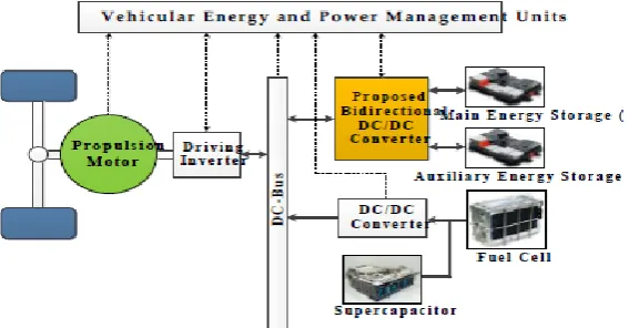
Fig 1: Typical schematic diagram for a FCV/HEV power system.
This manuscript is organized as follows:
Converter topology and operating modes are presented in section II. Section III presents the converter control scheme using fuzzy controller. The simulation & experimental results are presented in section IV. Section V gives the conclusion of this study.
II.
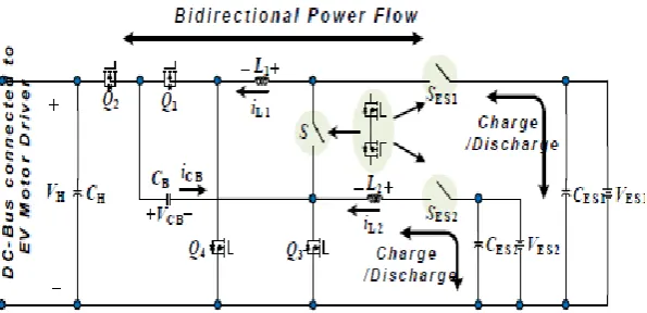
Topology And Operation Mode
Table1: Conduction status of devices for different operating modes. The four operating modes are as follows:
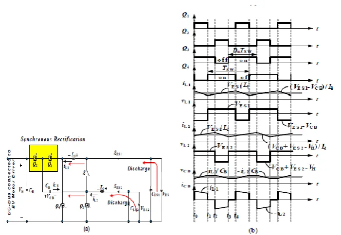
1] Low Voltage Dual Source Powering Mode:
Fig 3(a) & 3(b) shows the circuit and waveforms for this mode respectively. Here the switch S is turned off and the switches SES1, SES2 are turned on and the low voltage dual sources are supplying energy to dc bus and load. This mode can be explained in four states as follows:
a) State 1 [t0 < t < t1]: In this state Q1 & Q3 are turned on & Q2 & Q4 are turned off. In this state inductor current iL1 decreases linearly from its initial value whereas iL2 increases.
b) State 2 [t1 < t < t2]: In this state Q3 & Q4 are turned on & Q1 & Q2 are turned off. In this state inductor current iL1 and iL2 increases.
c) State 3 [t2 < t < t3]: In this state Q2 & Q4 are turned on & Q1& Q3 are turned off. In this state inductor current iL1 increases linearly from its initial value whereas iL2 decreases.
Fig 3: Low voltage dual source powering mode (a) Circuit diagram (b) Waveforms
2] High Voltage DC Bus Energy Regenerating Mode:
Fig 4(a) & 4(b) shows the circuit and waveforms for this mode respectively. Here the switch S is turned off and the switches SES1, SES2 are turned on and the kinetic energy stored in motor drive during braking operation is feedback to the low voltage dual source. This mode can be explained in four states as follows:
a) State 1 [t0 < t < t1]: In this state Q1 & Q3 are turned on & Q2 & Q4 are turned off. In this state inductor current iL1 decreases linearly from its initial value whereas iL2 increases.
b) State 2 [t1 < t < t2]: In this state Q3 & Q4 are turned on & Q1 & Q2 are turned off. In this state inductor current iL1 and iL2 increases.
c) State 3 [t2 < t < t3]: In this state Q2 & Q4 are turned on & Q1& Q3 are turned off. In this state inductor current iL1 increases linearly from its initial value whereas iL2 decreases.
d) State 4 [t3< t <t4]: In this state Q3 & Q4 are turned on & Q1 & Q2 are turned off. In this state inductor current iL1 and iL2 increases.
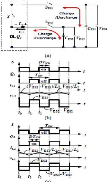
3] Low Voltage Dual Source Buck/Boost Mode:
Fig 5(a) shows the circuit and 5(b) & 5(c) shows waveforms for buck and boost mode respectively. In this state the energy transfer between main energy storage and auxiliary energy storage is observed and vice-versa. When duty cycle of S is controlled then power transfer from main to auxiliary storage takes place indicating converter in buck mode and when duty cycle of Q3 is controlled then vice-versa happens indicating converter in boost mode.
Fig 5: Low voltage dual source Buck/Boost mode (a) Circuit diagram (b) Waveforms for Buck mode (c) Waveforms for boost mode
III.
Converter Control
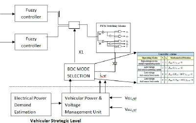
Fig. 6: Block diagram of the closed-loop control scheme
IV. Simulation And Experimental Results
(a)
(b)
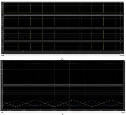
Fig. 7.Measured waveforms for low-voltage dual-source-powering mode: (a) gate signals; (b) output voltage and inductor currents.
(b)
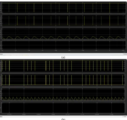
Fig.8. Measured waveforms for high-voltage dc-bus energy-regenerating mode: (a) gate signals; (b) output voltage and inductor currents.
(a)
(b)
V.
Conclusion
A Bidirectional DC-DC converter has been developed which interfaces low voltage dual energy storage and high voltage dc bus and also permits energy transfer between low voltage dual sources. The circuit diagram and its various operating modes are studied and explained in detail along with its simulation results using fuzzy controller and it can be observed that oscillations are reduced using this controller. Higher efficiencies can be achieved using this proposed model and can be applied in Hybrid Electric Vehicle System.
References
[1]. A. Khaligh and Z. Li, "Battery, ultracapacitor, fuel cell, and hybrid energy storage systems for electric, hybrid electric, fuel cell, and plug-in hybrid electric vehicles: State of the art," IEEE transactions on Vehicular Technology, vol. 59, no. 6, pp. 2806-2814, 2010. [2]. M. Ehsani, K. M. Rahman, and H. A. Toliyat, "Propulsion system design of electric and hybrid vehicles," IEEE Transactions on
industrial electronics, vol. 44, no. 1, pp. 19-27, 1997.
[3]. P. Thounthong, V. Chunkag, P. Sethakul, B. Davat, and M. Hinaje, "Comparative study of fuel-cell vehicle hybridization with battery or supercapacitor storage device," IEEE transactions on vehicular technology, vol. 58, no. 8, pp. 3892-3904, 2009
[4]. E. Schaltz, A. Khaligh, and P. O. Rasmussen, "Influence of battery/ultracapacitor energy-storage sizing on battery lifetime in a fuel cell hybrid electric vehicle," IEEE Transactions on Vehicular Technology, vol. 58, no. 8, pp. 3882-3891, 2009.
[5]. S. S. Raghavan, O. C. Onar, and A. Khaligh, ―Power electronic interfaces for future plug-in transportation systems,‖ IEEE Power Electron. Soc. Newsletter, vol. 23, Third Quarter 2010.
[6]. Y.-J. Lee, A. Khaligh, and A. Emadi, ―Advanced integrated bidirectional AC-DC and DC-DC converter for plug-in hybrid electric vehicles,‖ IEEE Trans. Veh. Technol., vol. 58, no. 8, pp. 3970–3980, Oct. 2009.
[7]. M. Pahlevaninezhad, P. Das, J. Drobnik, P. K. Jain, and A. Bakhshai, ―A new control approach based on the differential flatness theory for an AC/DC converter used in electric vehicles,‖ IEEE Trans. Power Electron., vol. 27, no. 4, pp. 2085–2103, Apr. 2012. [8]. Z-Source Inverter for Fuel Cell Vehicles, Oak Ridge Nat. Lab., Oak Ridge, TN, USA, Sep. 2005.
[9]. S.Miaosen, ―Z-source inverter design, analysis, and its application in fuel cell vehicles,‖ Ph.D. dissertation, Michigan State Univ., East Lansing, USA, 2007.
[10]. H.Wu, K. Sun, S. Ding, and Y. Xing, ―Topology derivation of nonisolated three-port dc-dc converters from DIC and DOC,‖ IEEE Trans. Power Electron., vol. 28, no. 7, pp. 3297–3307, Jul. 2013.
[11]. W. Li, J. Xiao, Y. Zhao, and X. He, ―PWM plus phase angle shift (PPAS) control scheme for combined multiport dc/dc converters," IEEE Trans. Power Electron., vol. 27, no. 3, pp. 1479–1489, Mar. 2012.
[12]. J. G. Pinto, V. Monteiro, H. Goncalves, and J. L. Afonso, ―On-board reconfigurable battery charger for electric vehicles with traction-to-auxiliary mode,‖ IEEE Trans. Veh. Technol., vol. 63, no. 3, pp. 1104–1116, Mar. 2014.
[13]. Y. K. Lo, S. C. Yen, and T. H. Song, ―Analysis and design of a double output series-resonant dc-dc converter,‖ IEEE Trans. Power Electron., vol. 22, no. 3, pp. 952–959, May 2007.
[14]. Y. Hu, W. Xiao, W. Cao, B. Ji, and D. John Morrow, ―Three-port dc-dc converter for stand-alone photovoltaic systems,‖ IEEE Trans. Power Electron., vol. 30, no. 6, pp. 3068–3076, Jun. 2015.
[15]. J. Zeng, W. Qiao, and L. Qu, ―An isolated three-port bidirectional dc-dc converter for photovoltaic systems with energy storage,‖ IEEE Trans. Ind. Appl., vol. 51, no. 4, pp. 3493–3503, Jul./Aug. 2015.
[16]. T. Bhattacharya, V. S. Giri, K. Mathew, and L. Umanand, "Multiphase bidirectional flyback converter topology for hybrid electric vehicles," IEEE Transactions on Industrial Electronics, vol. 56, no. 1, pp. 78-84, 2009.
[17]. H. Krishnaswami and N. Mohan, "Three-port series-resonant DC–DC converter to interface renewable energy sources with bidirectional load and energy storage ports," IEEE Transactions on Power Electronics, vol. 24, no. 10, pp. 2289-2297, 2009. [18]. Y.-C. Liu and Y.-M. Chen, "A systematic approach to synthesizing multi-input DC–DC converters," IEEE Transactions on Power
Electronics, vol. 24, no. 1, pp. 116-127, 2009.
[19]. K. Gummi and M. Ferdowsi, "Double-input dc–dc power electronic converters for electric-drive vehicles—Topology exploration and synthesis using a single-pole triple-throw switch," IEEE Transactions on Industrial Electronics, vol. 57, no. 2, pp. 617-623, 2010.