Speed Control of Three Phase Induction Motor
using Real Time Interface
D. Santhoshkumar V. Vimala
Assistant Professor PG Scholar
Department of Electrical & Electronics Engineering Department of Electrical & Electronics Engineering Vivekanandha institute of Engineering & technology for Vivekanandha institute of Engineering & technology for
Women, Tiruchengode, Namakkal District-637205. Women, Tiruchengode, Namakkal District-637205.
Abstract
It is very important to control the speed of induction motors in industrial and engineering applications. Efficient control strategies are used for reducing operation cost too. This paper presents a direct flux and torque control of three phase induction motor drive using PI and Fuzzy logic controller. The Direct Flux and Torque Control (DTC) is one of the most excellent direct control strategies of stator flux and torque ripple of Induction Motor Drive(IMD). The conventional method of DTC uses PI controller for speed regulation where speed is reduced under transient and dynamic state. This drawback was eliminated in proposed system by regulating the speed with the help of PI controller and torque controlled by fuzzy logic controller. The control system is based on DTC operating principles. This speed control process can be interfaced with MATLAB in real time.
Keywords: Fuzzy Logic controller, DTC technique, Torque ripple, interface, speed controller
________________________________________________________________________________________________________
I. INTRODUCTION
The induction motor, which is the most widely used motor type in the industry, has been favoured because of its good self-starting capability, simple and rugged structure, low cost and reliability. Induction Motors (IM) currently provide a very wide speed range, mechanically robust. The utility of induction motor is more than 70% in the electrical energy generation worldwide. A small improvement in efficiency wound significant energy savings are to be obtained. The Induction Motor (IM), especially the squirrel-cage type, is widely used in electrical drives and is responsible for most of the energy consumed by electric motors.
During last four decades AC drives are become more and more popular, especially induction motor Drives (IMD), because of robustness, high efficiency, high performance, and rugged structure ease of maintenance so widely used in industrial application, such as paper miles, robotics, steel miles, servos, transportation system, elevators, machines tools etc. The IMD control methods can be divided into two methods such as, scalar and vector control. The general classification of the variable frequency controls is presented and proposed control technique was shown in thick line in Fig.1. The scalar control is operating in steady state and controls the angular speed of current, voltage, and flux linkage in the space vectors.
Thus, the scalar control does not operating in the space vector position during transient state. The vector control, which is based on relations valid for dynamic states, not only angular speed and magnitude but also instantaneous position of current, voltage, and flux linkage of space vector are controlled. In the vector control, one of the most popular control method for induction motor drives, known as Field Oriented Control (FOC)is presented by F.Blaschke(Direct FOC) and Hasse (Indirect FOC) in early 1970’s, and FOC gives high performance, and high efficiency for industrial applications [1].
In this FOC, the motor equations are transformed into a coordinate system that rotates in synchronism with the rotor flux vector control [2]. The FOC is good in high dynamic performance, low stator flux and torque ripples, switching frequency, and maximum fundamental component of stator current, but FOC method has some drawbacks, such as requirement of two co-ordinate transformations, current controllers, and high machine parameter sensitivity. This drawback was eliminated using the new strategies for torque and flux ripple control of IMD using DTC was proposed by Isao Takahashi and Toshihiko Noguchi, in the mid 1980’s [3].Comparing with FOC, DTC has a simple control scheme and also very less computational requirements, such as current controller, and co-ordinate transformations are not required. The main feature of DTC is simple structure and good dynamic behaviour and high performance and efficiency [4,5,6].
regulator of IMD with the proposed technique using MATLAB/SIMULINK.MATLAB software is executed, then the motor will start to run and the speed will be controlled by means of interface with motor in real time.
Fig .1: Classification of induction motor control methods.
II. DIRECT TORQUE AND FLUX CONTROL OF IMD
The conventional DTC of IMD is supplied by a three phase, two level voltage source inverter (VSI). The main aim is to directly control of stator flux linkage or rotor flux linkage and electromagnetic torque by selection of proper voltage switching states of inverter.
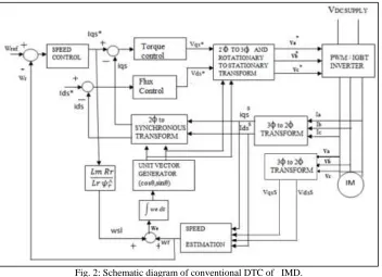
Fig. 2: Schematic diagram of conventional DTC of IMD.
The schematic diagram of conventional DTC of IMD is shown Fig. This schematic diagram consists of a torque and flux hysteresis band comparators (T, Ψ), voltage vector sector selection, stator flux and torque estimators (Ψs, Te), induction motor, speed controller, and voltage source inverter (VSI).
Pulse Width Modulation:
advantage of PWM is that power loss in the switching devices is very low. When a switch is off there is practically no current, and when it is on, there is almost no voltage drop across the switch. Power loss, being the product of voltage and current, is thus in both cases close to zero. PWM also works well with digital controls, which, because of their on/off nature, can easily set the needed duty cycle.PWM has also been used in certain communication systems where its duty cycle has been used to convey information over a communications channel.
Pulse Width Modulator:
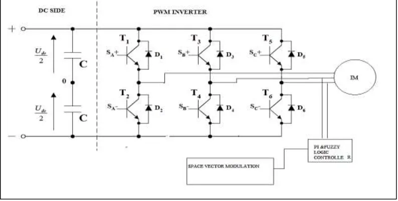
The structure of a typical 3-phase power inverter is shown in Figure 3.4, where VA VB, VC are the voltages applied to the star-connected motor windings, and where VDC is the continuous inverter input voltage.
Fig. 3: Basic scheme of 3-phase inverter
The six switches can be power BJT, GTO, IGBT etc. The ON-OFF sequence of all these devices must respect the following conditions: Three of the switches must always be ON and three always OFF. The upper and the lower switches of the same leg are driven with two complementary pulsed signals. In this way no vertical conduction is possible, providing care is taken to ensure that there is no overlap in the power switch transitions.
Voltage Source Inverter (VSI)
The three phase and two level VSI is shown in Fig.3, it has eight possible voltage space vectors, in those six active voltage vectors (U1-U6) and two zero voltage vectors (U7,U8), according to the combination of the switching modes are Sa, Sb, and Sc. When the upper part of switches is ON, then the switching value is ‘1’ and when the lower switch is ON, then the switching value is ‘0’.
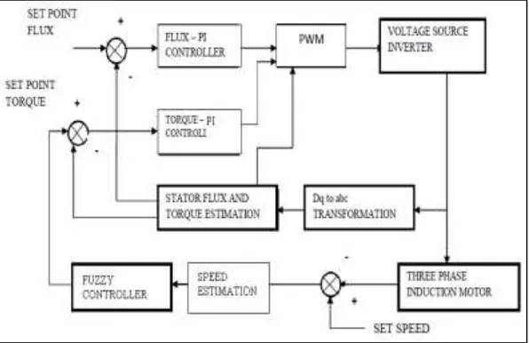
Fig. 4: Block Diagram of VSI
DTC Control:
dt d dt d i i R V V s s s s s s s
s r sin
r s r s T r
s L L
M J L L M T
As shown above in Equation which shows the torque produced is dependent on stator flux magnitude, rotor flux magnitude, and phase angle between the stator and rotor flux vectors. From equation torque the induction motor equation can be approximated by ignored the stator resistance.
III. SWITCHING TABLE FORMATION
The vectors Vi+1 or Vi-1 are selected to increase the amplitude of flux, and Vi+2 or Vi-2 to decrease it when flux is in sector I. If V0 or V7 is selected, then the rotation of flux is stopped and the torque decreases whereas the module of flux remains unchanged. Which shows that the choice of the vector tension depends on the sign of the error of flux is independent of its amplitude.
Table – 1
Switching table for DTC basis Sector
I II III IV V VI Flux Torque
F=1
T=1 V2 V3 V4 V5 V6 V1 T=0 V7 V0 V7 V0 V7 V0 T=-1 V6 V1 V2 V3 V4 V5
F=0
T=1 V3 V4 V5 V6 V1 V2 T=0 V0 V7 V0 V7 V0 V7 T=-1 V5 V6 V1 V2 V3 V4
Obviously, the exit of the corrector of flux must be a Boolean variable. One adds a band of hysteresis around zero to avoid unwanted commutations when the error of flux is very small. Indeed, with this type of corrector in spite of its simplicity, one can easily control and maintain the end of the vector flux in a circular ring form. The voltage vector switching table receives the input signals from change in flux hysteresis controller, change in torque hysteresis controller and another signal from space vector modulation block, hence develops the appropriate control voltage vector switching states for PWM inverter according to the Table.
Proposed Fuzzy Logic Controller:
IV. FUZZY CHARACTERISTICS
The fuzzy controller is characterized as follows:
1) Seven fuzzy sets for each input and output variables, 2) Fuzzification using continuous universe of discourse, 3) Implication using Mamdani's ‘min’ operator, 4) De-fuzzification using the ‘centroid’ method.
Fuzzification: the control process of converting a numerical variable (real number) convert to a linguistic variable (fuzzy number) is called fuzzification.
De-fuzzification: the rules of the FLC generate required output variable in a linguistic variable (Fuzzy Number), according to the real world requirements, linguistic variables have to be transformed to crisp output (Real number).
Database: the database stores the definition of the membership Function required by fuzzifier and defuzzifier [11].
A FLC converts a linguistic control strategy into an automatic control strategy and fuzzy rules are constructed by expert knowledge or experience database. Firstly, the input torque e ΔT (k) and the change in torque error * e ΔT (k) have been placed of the torque to be the input variables of the FLC. Then the output variable of the FLC is presented by the control of change in torque e ΔT . To convert these numerical variables into linguistic variables, the following seven fuzzy levels or sets are chosen as: NL (negative large), NM (negative medium), N (negative small), ZE (zero), PS (positive small), PM (positive medium), and PL (positive large) as shown in Fig.7.
Fuzzy Variables:
In the crisp variables of the torque error and change in torque error are converted into fuzzy variables e ΔT (k) and * e ΔT (k) that can be identified by the level of membership functions in the fuzzy set. The fuzzy sets are defined with the triangular membership functions.
Fuzzy Control Rules:
In the fuzzy membership function there are two input variables and each input variable have seven linguistic values, so 7x7=49 fuzzy control rules.
V. SIMULATION AND RESULTS
The conventional and proposed DTC MATLAB models were developed for 3hp IMD and the VSI input DC link voltage is 540V. The parameter values of IMD as shown in Table 6.The simulation results of proposed DTC for forward motoring operation as shown in Figs, it represents the stator current, stator flux, developed torque at no-load and full load, speed, and stator dq-axis for proposed DTC of IMD.
Fig. 7: Speed response of IMD.
The speed response of three phase induction motor shown in the Fig. It gives better performance with the range of 1500 rpm.
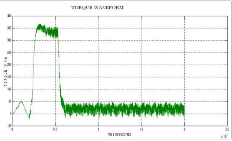
Fig. 8: Torque response
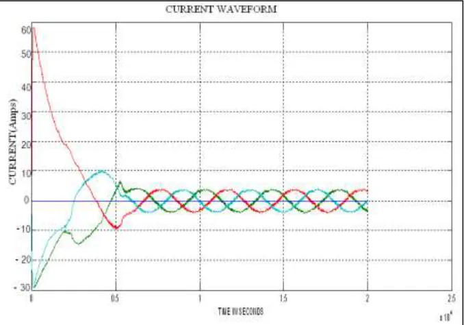
The resultant torque of the three phase induction motor is shown in the figure. That shows torque ripples reduction with the use of fuzzy logic controller. It gives better performance over the conventional method. The simulation diagram includes the Vector control block, space vector PWM, Speed and torque control of three phase Induction motor. The simulations results are rotor speed waveform, electromagnetic torque waveform, Stator current waveform are shown. Simulation results show robustness of the proposed method to system parameters variations
VI. CONCLUSION
control the limits of the torque and flux. The simulation result of both conventional and proposed techniques was carried out for DTC of three-phase IMD, among both of them proposed control technique is superior for good speed regulator, low stator flux linkage, and torque ripples under transient and dynamic state operating conditions. The simulation result shows the low stator flux linkage, torque ripples and good speed regulator, with the proposed DTC technique than conventional DTC technique.
REFERENCES
[1] F. Blaschke, “The principle of field-orientation as applied to the trans vector closed-loop control system for rotating-field machines”, Siemens Rev., vol. 34,
pp. 135-147, 1988.
[2] G.S. Buja, M.P.Kazmierkowski, “DTC of pwm inverter-fed AC motors – A Survey”, IEEE Trans. on Ind. Elec., volume 54, no. 4, 2004.
[3] I. Takahashi and T. Noguchi, “A new quick response and high efficiency control strategy of an induction motor”, IEEE Trans. Ind. Appl., vol. 22,no. 5, pp.
820-827, 1986.
[4] M. Dependrock, “Direct self-control (DSC) of inverter-fed induction machine”, IEEE Trans. on Power Electronics, volume 22, no. 5, pp. 820- 827,
September/October 1986.
[5] Tang L., Zhong L., Rahman M.F., Hu Y., “A novel direct torque controlled interior permanent magnet synchronous machine drive with low ripple in flux
and torque and fixed switching frequency”, IEEETransactions on Power Electronics, 19(2), p.346-354, 2004.
[6] I. Takahashi and Y. Ohmori, “High-performance direct torque control of induction motor”, IEEE Trans. Ind. Appl., vol. 25, no. 2, pp. 257-264,1989.
[7] P. Vas, Sensorless vector and direct torque control, Oxford University Press, 1998.
[8] C. F. Hu, R. B. Hong, and C. H. Liu, “Stability analysis and PI controller tuning for a speed –sensorless vector-controlled induction motor drive”, 30th Annual
Conference of IEEEIndus. Elec., Society, 2004, IECON, vol.1, 2-6 Nov. 2004, pp. 877-882, 2004.
[9] M.N. Uddin, T. S. Radwan, and M. A. Rahman, “Performance of fuzzylogic- based indirect vector control for induction motor drive”, IEEETrans. Ind. Appl.
Vol. 38, no. 5, PP. 1219-1225, September/Oct. 2002.
[10] B.K.Bose, “Modern Power Electronics and AC Drives”, Prentice Hall Indic, 2006.
[11] Suresh Mikkili, A.K. Panda “PI and Fuzzy Logic Controller based 3- phase 4-wire Shunt active filter for mitigation of Current harmonics with Id-Iq Control
Strategy”, Journal of power Electronics (JPE), vol. 11, No.6, Nov. 2011.
[12] AnasMohdNazlee, Nor Hisham Hamid, Fawnizu Azmaid Hussin, and Noohul Basheer Zain Ali. (2010), “Space Vector PWM for PMSM Simulation Using
Matlab Simulink “, IEEE Trans.
[13] Bimal K .Bose, (2011), ‘‘Modern Power Electronic and Ac Drives”, Prentice-Hall PTR, Book, pp .29-30 and pp56-73.
[14] M. Lazim, M. Al-khishali, A. Isa, "Space Vector Modulation Direct Torque Speed Control Of Induction Motor," The 2ndInternational Conference on Ambient