International Journal of Civil & Environmental Engineering IJCEE-IJENS Vol:12 No:04 70
Abstract— Numerical fire simulations (in terms of Computational Fluid Dynamics (CFD)) are becoming increasingly pervasive in fire safety analysis, because they offer many benefits beyond those offered by traditional methods. Nevertheless, such simulations are time-consuming and require a relatively large amount of computation power for use in engineering applications. Therefore, compared to other methods, the use of numerical fire simulations for construction projects is not as common as it should be given their benefits. Moreover, the results of a fire safety analysis affect the different parties of a project, such as the architects, structural engineers, or project managers. While these parties are usually unfamiliar with numerical fire simulations, they require easy access to the results of such simulations, which are usually conducted by a fire safety engineer. These aspects have led us to the present research on the development of new IT solutions for convenient deployment of numerical fire simulations, including suitable data preparation and data transmissions. This
paper presents a novel distributed cloud-computing
infrastructure to simplify the use of the numerical fire simulations for construction projects and encourage “fire safety teamwork” among the different parties involved in a project. Using this cloud system, clients can carry out numerical fire simulations on their own regardless of their location or device. The simulation module described herein runs on a computer cluster in order to increase the system performance.
Index Term— Numerical Fire Simulation, Computational Fluid Dynamics, Parallel Computing, Cloud Computing.
I.
I
NTRODUCTIONNumerical simulations have become an essential aspect of different engineering fields. However, working with numerical simulations requires a high level of computer performance and hardware resources. Therefore, programmers have attempted to solve this issue by using new technologies such as “parallel computing,” “cloud computing,” and “distributed computer infrastructures.” One of the important fields widely deploying numerical simulations is fire safety engineering. Numerical fire simulations are time-consuming and expensive, and consequently, their deployment is limited to buildings with a high level of security or with complex architecture [1]. Nevertheless, owing to the rapid development of hardware and software solutions in recent years, fire safety engineers frequently use numerical methods to simulate fire scenarios and analyze the safety aspects of buildings. The most important aspects of fire safety numerical simulations are the spreading of smoke and fire inside a building, the local variations in
temperature and pressure, changes in soot density and toxic gas concentration, and macroscopic evacuation analyses on the behaviors of the building occupants [2]. In these cases, the building objects essentially determine the geometric boundary conditions of the fire scenarios.
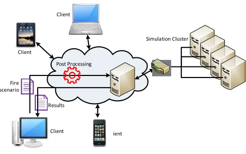
Different companies with different responsibilities are involved in construction projects. The digital data transmission described herein is mainly conducted using external data storage devices or simple non-automated solutions through Internet resources such as email or FTP connections. In fire-safety-related collaborations, the results of numerical fire simulations are also important for the other parties of a construction project. For instance, based on these results, architects may customize the building escape routes, or structural engineers may use suitable fire-resistive materials for the building elements. Because fire simulation results are normally available only at the simulation computer, the data transmission in such cases requires considerable effort. To overcome these issues, a comprehensive distributed infrastructure for numerical fire simulations is needed. Such a distributed system should offer special services for performance sharing, data preparation, and self-organized data transmissions. These services should be delivered through a cloud-computing implementation. Not only should the cloud system accelerate the work process during the construction project but the different parties involved in the project should also work closer together and encourage teamwork. We have prototyped the Numerical Fire Simulation Cloud (NFSC) as a distributed computer infrastructure for numerical fire simulations in a cloud. Fig. 1 shows the concept of this cloud system. Since numerical simulations include time-consuming routines and demand a large amount of computational power, the simulation module used in the new distributed system is based on a computer cluster. This module, i.e., a fire simulation cluster, is offered by services suitable for realizing a cloud computer that is accessible to all individual construction project parties through the Internet.
A Cloud System for Numerical Fire Simulations
Fire scenario
Post Processing
Simulation Cluster
Results
Client Client
Client
Client
Fig. 1. Concept of the Numerical Fire Simulation Cloud (NFSC)
Fig. 2 shows the activities of this concept sequence diagram.
:Client :Fire Scenario :Cloud
create()
modify() upload()
start
Results Results
Post Processing
Fig. 2. Activities of the Numerical Fire Simulation Cloud (NFSC)
II. RELATED WORK
Although cloud computing is a new IT technology, its deployment has been steadily increasing in different engineering fields, including civil engineering.
projects have dealt with CFD simulations and cloud computing. One of these projects is “Caedium” developed by “Symscape” [3]. Caedium offers the ability to outsource intensive numerical CFD simulations to a cloud service. However,
not offer cloud service, and the clients need to have a Windows Azure account. Another interesting cloud project
engineering is “Autodesk 360” [4]. Autodesk 360 is a cloud-computing platform that offers access to storage, a collaboration workspace, and several cloud services. Energy and structural analyses, a conceptual design
(Building Information Modeling) management solutions are some of the services provided by Autodesk 360. Nevertheless, there are no services available for fire simulations and safety analyses in this cloud-based platform. The authors in [ introduced a hybrid simulation and visualization approach
Simulation Cluster
Numerical Fire Simulation Cloud (NFSC)
this concept through a UML
:Simulation Cluster
start()
Results
Processing
Simulation
the Numerical Fire Simulation Cloud (NFSC)
Although cloud computing is a new IT technology, its steadily increasing in different civil engineering. Some ambitious with CFD simulations and cloud computing. “Caedium” developed by “Symscape” ]. Caedium offers the ability to outsource intensive numerical , this system does to have a Windows ting cloud project for civil ]. Autodesk 360 is a computing platform that offers access to storage, a collaboration workspace, and several cloud services. Energy conceptual design, and BIM management solutions are services provided by Autodesk 360. Nevertheless, for fire simulations and safety based platform. The authors in [5] rid simulation and visualization approach in
which a mobile application (“SimAnroid”) side and a simulation server is hosted in a cloud. concept, the authors considered only
forest fires in their fire simulations, space such as a building. Therefore, unsuitable for fire safety analyses of
project similar to SimAnroid is “LandView”
provides GIS-based open-air fire simulations using Windows Azure [6]. As a result, there is a lack of
cloud-computing systems for numerical fire simulations emphasizes the need for the system proposed in this paper.
III. FIRE MODELS For the simulation of fire scenarios, we ignition at the fire source, as well as the building, using appropriate methods [ three fire models are employed for this purpose.
A. Physical Fire Models (Real Experiments) As real experiments, physical fire models prototypes. They represent real case simplifications and scales [8], and are
laboratories (Fig. 3). Through such experiments, fire behavior can be explained in fundamental terms
experiments, mathematical equations can be
the fire scenarios. Physical fire models are complex, expensive and limited because of the geometric
Consequently, these kinds of models simulation of partial aspects of a fire scenario behavior of the fire source [8].
Fig. 3. A real fire experiment at the National Institute of Technology (NIST)
B. Zone Fire Models
In zone models, the fire area is
homogeneous zones (layers). This division is usually between a hot upper layer, including the smoke
cold gases (Fig. 4). The basic assumption here is that the model a mobile application (“SimAnroid”) runs on the client side and a simulation server is hosted in a cloud. Using this only open-air fires such as and not fires in an enclosed e, this development is also of construction projects. A to SimAnroid is “LandView” by GCS, which simulations using Windows is a lack of well-known for numerical fire simulations, which the system proposed in this paper.
ODELS
simulation of fire scenarios, we need to model the fire the fire development inside using appropriate methods [7]. The following three fire models are employed for this purpose.
Physical Fire Models (Real Experiments)
fire models are fire scenario . They represent real cases that consider possible and are conducted in controlled . Through such experiments, fire behavior mental terms [9]. In these types of equations can be used to simulate hysical fire models are complex, expensive, and limited because of the geometric constraints. of models are used only for the simulation of partial aspects of a fire scenario, particularly the
National Institute of Standards and
International Journal of Civil & Environmental Engineering IJCEE
properties such as temperature or density are approximated through each zone [10]. Between these zones
equations is defined to solve the zone fire model. These equations utilize the conservation of mass (continuity equation), the conservation of energy (the first law of thermodynamics), the ideal gas law, and the
density and internal energy [11]. A zone fire model is suitable for simple issues and can be solved manually
assumption that the fire properties are the same throug
zone is not valid for arbitrarily large spaces or for long, narrow spaces such as corridors and shafts [12]. Furthermore,
their extreme simplicity, zone fire models do not deliver a realistic representation of fire scenarios in constructions with complex architecture, and are therefore not suitable for safety analyses of such cases [13].
Flue Gas Layer
Cold Air Layer
Ventilation
Fire Source Plume Thermal Interface
Fig. 4. Zone fire model with two zones
C. CFD Fire Models
Computational Fluid Dynamics (CFD) deals with computer-aided solutions for fluid dynamics equations in field models. Currently, the use of CFD methods is increasing in various engineering fields, which is particularly due to the latest developments in the hardware and software industry has resulted in the development of computers
performance. The idea to use computer power for numerical fire simulations is not new. The first applications of CFD techniques in fire engineering appeared in the late 1970s [14]. Compared to zone models, CFD fire model accurate, make three-dimensional simulations
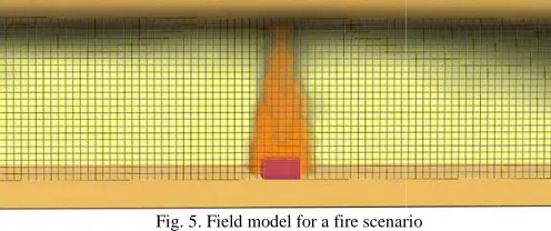
consider more of the processes involved in a fire scenario [ (Fig. 5).
Fig. 5. Field model for a fire scenario To build a model for fire scenarios, we should
only model the fire source but also the development process of
International Journal of Civil & Environmental Engineering IJCEE-IJENS Vol:12 No:04
temperature or density are approximated zones, a system of defined to solve the zone fire model. These the conservation of mass (continuity (the first law of the definitions of zone fire model is suitable manually. However, the assumption that the fire properties are the same throughout each valid for arbitrarily large spaces or for long, narrow ]. Furthermore, owing to zone fire models do not deliver a realistic representation of fire scenarios in constructions with a not suitable for the
Zone 1
Zone 2
Fire Source Plume
ones
Computational Fluid Dynamics (CFD) deals with dynamics equations in field models. Currently, the use of CFD methods is increasing in various engineering fields, which is particularly due to the latest developments in the hardware and software industry, and resulted in the development of computers with higher performance. The idea to use computer power for numerical fire simulations is not new. The first applications of CFD appeared in the late 1970s [7], CFD fire models are more possible, and can a fire scenario [15]
cenario
should be able to not model the fire source but also the development process of
the fire and smoke. To this end, various approaches utilized numerical methods. One famous approach introduced by Yeoh and Yuen [7],
the following aspects for modeling a fire source: • energy release process
• radiation • soot production • solid pyrolysis
To model the development of fire and smoke inside building, they recommend consider the following processes:
• fluid flow • heat transfer • turbulence
For a simulation of a fire scenario,
simulation area (domain) into a number of small control volumes (finite elements). As a result, a mesh
The CFD solver then uses certain conservation equations (Navier–Stokes) to solve the
simultaneously at each mesh intersection (or in the middle of each finite element) [16]. In the case of fire simulations following unknowns should generally
• velocity and its three components • temperature
• pressure • density
For this aim, the CFD solver defines mathematical equations based on the conservation laws for mass, momentum energy, as well as equations of state for ideal gases. Basically, the aim of a CFD simulation is to solve these equations for each mesh intersection. As the simulation of a fire scenario inside a building is a complex process, CFD methods are a
solution. Several fire simulators are overview of these simulators is given in [ [19], Fire Dynamics Simulator (FDS) [ Kobra3D [22] are the most commonly
CFD fire simulations. The evaluation criteria for these programs are as follows:
• Suitability of CFD fire simulations • Validation
• Ongoing development (age • Price
• Open source (partly or completely) • Distribution/popularity
In this work, we used FDS for numerical simulations in the cloud environment. This program
practical fire problems in fire safety engineering
designs for handling fire and smoke. FDS assumes that fl such as smoke moving during a fire are turbulent with a high Reynolds number (similar to meteorological
assumption makes it possible for FDS to employ Navier–Stokes equations to solve the
free program developed by the National Institute of Standards and Technology (NIST) in the US
cross-platform software. FDS can be controlled through IJENS Vol:12 No:04 72
, various approaches have numerical methods. One famous approach was who suggested considering ling a fire source:
To model the development of fire and smoke inside a they recommend consider the following processes:
the CFD solver divides the simulation area (domain) into a number of small control volumes (finite elements). As a result, a mesh is constructed. uses certain conservation equations the required unknowns simultaneously at each mesh intersection (or in the middle of n the case of fire simulations, the
generally be determined [17]: its three components
this aim, the CFD solver defines mathematical equations based on the conservation laws for mass, momentum, and as well as equations of state for ideal gases. Basically, the aim of a CFD simulation is to solve these equations for each simulation of a fire scenario inside a CFD methods are a suitable based on CFD methods. An is given in [18]. SMARTFIRE or (FDS) [20], Star-CD [21], and commonly deployed programs for The evaluation criteria for these
CFD fire simulations for buildings
Ongoing development (age and generation)
Open source (partly or completely)
command line, and its input file is a simple plain-text file. Therefore, it is possible to generate FDS input files from third-party applications. In addition, FDS allows simulations to be executed on distributed infrastructures through a Message Passing Interface (MPI) [23]. These properties allow the implementation of an interface within the cloud, as well as precision between the compute nodes of the simulation cluster. The idea here is to create fire scenarios (FDS input files) on a client device, connect to a cloud computer through a network device, send the FDS input files to the cloud computer, and begin the simulation at that location. Behind this cloud is a computer cluster responsible for running the simulations.
IV. NUMERICAL FIRE SIMULATIONS IN A CLOUD
A. Overview of Cloud Computing
Cloud computing can be defined as a computer system that delivers applications or hardware resources as services over the Internet [24]. It can also be considered as a pool of configurable computing resources such as applications, servers, and storage [25]. The most important characteristic of cloud computing is that the computing itself takes place “in the cloud” [26]. Furthermore, the deployment of such a system is independent of the client location or device. Cloud computing services can be categorized as follows [25]:
• Software as a Service (SaaS) • Infrastructure as a Service (IaaS) • Platform as a Service (PaaS)
The authors in [24] count business continuity and service availability as opportunities of cloud computing. For this reason, large software providers are investing massively in IT solutions that involve cloud computing. For instance, Amazon with its AWS (Amazon Web Services) [27], Google with its AppEngine [28], and Microsoft with Windows Azure [29] offer powerful cloud systems for the development or deployment of various services. Furthermore, the video game industry (e.g., Sony with PlayStation [30] and Microsoft with Xbox [31]) is also investing in cloud systems for online gaming or customer database maintenance. Nevertheless, the massive collection of data in cloud systems has made them attractive targets to hackers. For instance, the credit card data theft from the PlayStation cloud in April 2011 caused a loss of $3.1bn for Sony [32], [33]. Therefore, security aspects must be considered in the implementation of cloud computers. Therefore, NFSC uses a user authorization system as well as a special secure data transmission, which will be discussed in a later section. NFSC has a distributed system architecture based on a Client–Server model. The server components of this system are provided as services in the cloud, allowing clients to share information, resources, and software. NFSC can be considered an Infrastructure as a Service (IaaS) which offers a computer cluster and a relational database as its infrastructure. Furthermore, it includes software service (SaaS) allowing the clients to run and control the fire simulations as well as access the simulation results. Moreover, the data transmissions of this
system are self-organized. Thus, clients can use the cloud services and computing resources without having to deal with the hardware and software configurations behind them. Based on the advantages of cloud computing, and after a thorough discussion on this subject, the authors in [34] suggested developers to design their next-generation systems to be deployable in a cloud computing environment.
B. Cluster Infrastructure for Numerical Fire Simulations As mentioned above, the resulting control volumes (cells) in CFD fire models are usually very small (between 5 and 25 cm). This leads to a large number of mesh intersections in the CFD model of a building or building section. Consequently, the number of equations will also be large, and solving these equations demands a high level of computational power. To overcome this issue, we must use either supercomputers or parallel computing in a cluster. Supercomputers are generally expensive and require extensive maintenance. Therefore, they are not suitable for typical numerical fire simulation issues. The authors in [35] pointed out that issues pertaining to the problem size, accuracy requirements, and storage restrictions of numerical fire simulations are steadily increasing. Owing to these facts, an efficient numerical simulation of realistic fire scenarios can only be obtained on high-performance computers with multi-processor architecture. However, this is not suitable for normal engineering use. Therefore, the idea of computer clusters is suitable for our aim. Although it is not easy to configure computer clusters, cluster maintenance is generally easier and the costs are usually cheaper than those required by a supercomputer are. Moreover, a computer cluster can consist of common PCs and is scalable, and thus its use for any medium-sized construction project is possible.
The applications of our distributed infrastructure for fire simulations are offered as services in a cloud computer to reduce the difficulties of their use. Hence, fire safety engineers do not need to deal with the configurations behind the distributed system and are also able to simulate fire scenarios with a strong infrastructure. Furthermore, cloud clients (different project parties) are able to access the simulation results from anywhere using the Internet.
International Journal of Civil & Environmental Engineering IJCEE
[37]. Thus, employing a computer cluster can
carried out more quickly. The hardware architecture of a computer cluster can be classified into the following four categories:
• SISD (Single Instruction, Single Data) • SIMD (Single Instruction, Multiple Data) • MISD (Multiple Instruction, Single Data) • MIMD (Multiple Instruction, Multiple Data) This classification was first presented in 1966 by Michael J. Flynn [38], and is therefore also called Fynn’s taxonomy. processing units in SIMD clusters have identical task (instruction) that should be carried out at
partitions [39]. SIMD clusters are suitable for numerical fire simulation issues, because in this kind of simulation, the calculation task at each mesh intersection is identical (single instruction), but the input data vary (multiple data).
C. Performance Measurement
Since not any part of a calculation task can be divided into subtasks to be conducted simultaneously, the performance of p processing units will not be identical to the p-fold performance of a single processor. Hence, the performance of a computer cluster for a specific problem size can be determined
its parallelizable and non-parallelizable parts
called overhead. Thus, a non-parallelizable part has to be processed sequentially. Moreover, the management of subtasks, i.e., their splitting and summing up, as well as the communication between the processing units,
computer performance [40]. There are generally two performance measures that can be employed for
of parallel systems: speedup and efficiency [41
1) Speedup
The speedup Sp is the ratio of the time required
specific problem on a single processing unit to the solution time required for the same problem on a cluster with p processing units with similar properties as the single processing unit In equation (1), t1 is the solution time on a single processing
unit, tp is the solution time on p processing units
specific problem with a fixed size.
p
p C t t t
t
C/ )/( / ) /
(
Sp = 1 = 1
2) Efficiency
The efficiency Ep can be employed to determine how
single processing unit is invested in a computer cluster. In other words, Ep is the average utilization of p allocated processing
units [41]. It should be noted that when ignoring
an efficiency of 100% is only expected from a single processing unit, and that parallel systems cannot generally achieve rate.
p Sp/ Ep =
International Journal of Civil & Environmental Engineering IJCEE-IJENS Vol:12 No:04
ter can allow tasks to be . The hardware architecture of a computer cluster can be classified into the following four
SISD (Single Instruction, Single Data) SIMD (Single Instruction, Multiple Data)
Instruction, Single Data) MIMD (Multiple Instruction, Multiple Data)
1966 by Michael J. also called Fynn’s taxonomy. The have identical tasks at different data for numerical fire simulation issues, because in this kind of simulation, the calculation task at each mesh intersection is identical (single
(multiple data).
Since not any part of a calculation task can be divided into subtasks to be conducted simultaneously, the performance of p fold performance of a single processor. Hence, the performance of a computer cluster for a specific problem size can be determined based on parallelizable parts, which are also parallelizable part has to be sequentially. Moreover, the management of their splitting and summing up, as well as the , requires greater ]. There are generally two be employed for an evaluation
41].
required to solve a specific problem on a single processing unit to the solution time er with p processing processing unit [37]. is the solution time on a single processing is the solution time on p processing units, and C is a
(1)
can be employed to determine how usefully a single processing unit is invested in a computer cluster. In other is the average utilization of p allocated processing ignoring the I/O effort, a single processing generally achieve this
(2)
D. Case Study: Performance Measur
Since increasing the number of processing units always lead to a higher level of performance task requires a different number of
parallelization. Hence, the hardware architecture of
cluster used in the NFSC must be scalable. This means that the number of processing units should be variable. Depending on the problem size and boundary conditions in the fire scenario, a different cluster scale is required. To clarify this fact
the system performance, we conducted a series of simulation tests and measured the NFSC performance
These tests were carried out for three
each with fixed cell numbers and various simulation times and processing units. We then calculated
for each case. It should be noted that the concept of should be suitable for daily use in
way to gain a wider acceptance of numerical fire simulations for such projects. Therefore, the tests at this stage are carried out using common PCs that are available in any construction company. Five office PCs each with
Quad Processor and 4 GB RAM simulation cluster described herein combined using a Gigabit Network Switch.
The fire scenarios tested each have a different level of difficulty (different numbers of cells and objects). The complexity of the fire scenario significantly affects
power. In scenarios with various building objects, vortices will appear, and consequently, more computation power
Furthermore, a detailed definition of the burning materials in a fire scenario will require a greater computational performance Therefore, the optimal number of processing units
for each fire scenario varies.
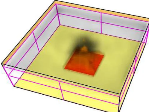
Scenario 1 contains a simple fire source in an open environment with 25600 cells (Fig.
in this scenario and the fire source burns simulation time for scenario 1 is set to 60 s 25 cm.
Fig. 6. Scenario 1: An open
IJENS Vol:12 No:04 74
Measurement of NFSC Since increasing the number of processing units does not
level of performance, each simulation task requires a different number of units to achieve an optimal parallelization. Hence, the hardware architecture of a computer NFSC must be scalable. This means that the number of processing units should be variable. Depending on the problem size and boundary conditions in the fire scenario, a different cluster scale is required. To clarify this fact and verify , we conducted a series of simulation performance for each simulation.
hree different fire scenarios, each with fixed cell numbers and various simulation times and calculated the speedup and efficiency for each case. It should be noted that the concept of the NFSC in construction projects as a acceptance of numerical fire simulations . Therefore, the tests at this stage are carried are available in any construction office PCs each with a 2.5 GHz Intel Core 2 Quad Processor and 4 GB RAM were employed for the described herein. The compute nodes were a Gigabit Network Switch.
have a different level of difficulty of cells and objects). The complexity of the affects the required calculation ower. In scenarios with various building objects, vortices will more computation power is needed. Furthermore, a detailed definition of the burning materials in a will require a greater computational performance. refore, the optimal number of processing units employed
fire source in an open-air environment with 25600 cells (Fig. 6). There is no ventilation in this scenario and the fire source burns continuously. The simulation time for scenario 1 is set to 60 s, and the cell size is
Scenario 2 simulates a fire source in a small library (Fig. 7 This scenario contains two openings (doors) that
burning process. Moreover, the books and shelves have a detailed material definition. Scenario 2 contains 332800 cells with the same cell size as in scenario 1. The simulation time for all tests under this scenario is set to 10 s.
Fig. 7. Scenario 2: A fire in a small library
The third scenario models a fire inside a building. Unlike other scenarios, this scenario contains several
openings that make simulating the spreading
smoke more complicated (Fig. 8). There are 1689600 cells generated for this scenario, which is considerable
that in the other test cases. The simulation time here is set to 10 s.
Fig. 8. Scenario 3: Fire inside a building
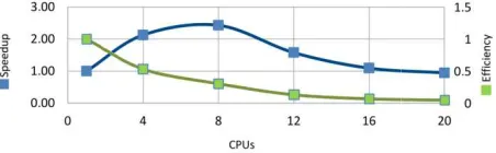
The tests were carried out with a variable number (1, 4, 8, 12, 16, and 20 CPUs). For all test cases the speedup and efficiency, the results of which Figs. 9 through 11.
Fig. 9. Speedup and efficiency for scenario 1
ource in a small library (Fig. 7). that accelerate the . Moreover, the books and shelves have a detailed material definition. Scenario 2 contains 332800 cells, cell size as in scenario 1. The simulation time for
ibrary
a building. Unlike the several rooms and ing of the fire and There are 1689600 cells considerable higher than ation time here is set to 10
building
variable number of processors and 20 CPUs). For all test cases, we calculated of which are shown in
Speedup and efficiency for scenario 1
Fig. 10. Speedup and efficiency for scenar
Fig. 11. Speedup and efficiency for scenario 3
The test results show that the optimal cluster size depends on the model characteristics. Scenario 1 includes a small number of cells, and its boundary conditions are simple.
scenario, the fire source burns in an open is stable. There is no ventilation or
turbulence effects are extremely small. Although employing more processing units for this simple scenario generally decreases the duration of the simulation
can be achieved using eight processing units. Scenario 2 simulates a small library
as obstacles, books as the burning material (doors) for ventilation, and therefore there
areas in this scenario. Furthermore, scenario 2 has more cells than scenario 1. Because of these conditions, the simulation tasks are larger and more extensive
scenario 1. Thus, for this scenario, more processing units should be deployed to obtain the optimum
In comparison to the first two scenarios
scenario 3 is extremely high, and hence, the problem size here is much larger. For this reason, this scenario requires computing power to achieve a higher speedup.
It should be noted that despite acceptable values for
the achieved efficiencies of all three scenarios are not high. Parallelization generally results a reduction
increasing the number of processors
efficiency reduction in these case studies is high a comparison of the calculated efficiency after
simulation of the thermal fluid–structure interaction on a computer cluster. The calculation in this example can be considered equal to a fire simulation. These results show that the reductions in efficiency in our test cases are
This is not because of the system design of the algorithm of FDS. One reason for
these tests is that FDS was not originally developed for parallel simulation. Therefore, if user
simulations simultaneously, they have to define extra meshes for each required process. This means that paralle
Speedup and efficiency for scenario 2
up and efficiency for scenario 3
show that the optimal cluster size depends on the model characteristics. Scenario 1 includes a small number and its boundary conditions are simple. Under this fire source burns in an open-air environment and or obstacles. Therefore, the turbulence effects are extremely small. Although employing more processing units for this simple scenario generally he simulation, the maximum speedup
processing units.
including walls and shelves burning material, and openings fore there are more turbulence areas in this scenario. Furthermore, scenario 2 has more cells than scenario 1. Because of these conditions, the simulation and more extensive compared to those in . Thus, for this scenario, more processing units
the optimum speedup.
two scenarios, the number of cells in and hence, the problem size here this scenario requires greater computing power to achieve a higher speedup.
International Journal of Civil & Environmental Engineering IJCEE
combined with mesh separation. For instance processing tasks, we have to divide the simulation
different meshes. The next difficulty here is that the mesh transition in FDS is a slow process. Hence, a greater number of meshes results more system overhead, and consequently efficiency.
Fig. 12. Efficiency in the numerical simulation of a thermal fluid interaction [42]
V. CONCLUSIONS
This work introduced the concept of a distributed computer infrastructure for numerical fire simulations in a cloud (NFSC). This cloud system is designed to gain
acceptance of CFD fire simulations in the daily practice of fire safety engineering. NFSC offers numerical fire simulations as a service to its clients. The simulation service in NFSC runs on a computer cluster for a higher level of computing performance. Offering numerical fire simulations and making the results available to the clients, i.e., the different
construction project, a strong and robust computing infrastructure can be accessed from any location
addition, with this system, the clients are not forced to deal with the complex configurations of parallel computing
transmissions between remote computers. Since the concept of NFSC is relatively simple, it can be realized using
software on normal PCs. This makes the system flexible and employable for many construction projects.
Our case studies with NFSC show that this concept is a suitable solution for reducing the simulation time of
tasks. Nevertheless, the utilization of hardware resources is low. Thus, this system is particularly suitable for companies that want to deploy their pre-existing hardware resources to build a cloud system for their own numerical fire simulations. As future work, we will work on applications
users to work with the NFSC on their mobile devices applications should make it possible for users
simulations and access the simulation results. Our second objective is the visualization of simulated fire scenarios on mobile devices. Moreover, we are working on
for NFSC using HTML5 technology to offer an interactive modification of the building elements.
REFERENCES
[1] U. Rüppel, P. Abolghasemzadeh, BIM-based immersive evacuation
simulations, in: IKM 2009, digital proceedings, Weimar, 2009.
International Journal of Civil & Environmental Engineering IJCEE-IJENS Vol:12 No:04
combined with mesh separation. For instance, to run 12 divide the simulation area into 12 different meshes. The next difficulty here is that the mesh a greater number of and consequently, less
thermal fluid–structure
the concept of a distributed computer infrastructure for numerical fire simulations in a cloud system This cloud system is designed to gain greater in the daily practice of fire merical fire simulations as a service to its clients. The simulation service in NFSC runs on a a higher level of computing performance. and making the results erent parties of a construction project, a strong and robust computing location at any time. In are not forced to deal with the complex configurations of parallel computing or data Since the concept of using open-source PCs. This makes the system flexible and
SC show that this concept is a suitable on time of large simulation tasks. Nevertheless, the utilization of hardware resources is suitable for companies existing hardware resources to numerical fire simulations. future work, we will work on applications that will allow
on their mobile devices. Such ers to control the simulations and access the simulation results. Our second objective is the visualization of simulated fire scenarios on mobile devices. Moreover, we are working on a Web interface NFSC using HTML5 technology to offer an interactive
based immersive evacuation simulations, in: IKM 2009, digital proceedings, Weimar, 2009.
[2] P. Abolghasemzadeh, Integration von numerischer Brandsimulation in
die digitale Gebäudemodellierung für die Anwendung im Einsatzfall, in: 5. Anwender-Treffen der FDS-Usergroup, 2011, pp. 43
[3] Symscape, Caedium, Available:
http://www.symscape.com/product/caedium
[4] Autodesk, Autodesk 360, Available: https://360.autodesk.com
[5] E. Mancini, G. Wainer, K. Al-Zoubi, O. Dalle, O., Simulation in
Cloud Using Handheld Devices, in: 12th IEEE/ACM International Symposium on Cluster, Cloud and Grid Computing, 2012, pp. 867
[6] GCS Research, LandView, Available:
http://globe.gcs-holdings.net/landview/
[7] G. H. Yeoh, K. K. Yuen, Computational Fluid Dynamics in Fire
Engineering: Theory, Modelling and Practice, Butterworth 2009.
[8] D. Hosser, Leitfaden Ingenieurmethoden des
zurFörderung des Deutschen Brandschutzes eV (vfdb)
[9] N. De Mestre, E. Catchpole, D. Anderson, R. Rothermel, Uniform
propagation of a planar fire front without wind, Combustion Science and Technology 65 (4-6), 1989, pp. 231–244.
[10] W. Davis, N. I. o. Standards, T. (US), The Zone Fire Model JET: A Model
for the Prediction of Detector Activation and Gas Temperature in the Presence of a Smoke Layer, US Dept. of Commerce, Technology Administration, National Institute of Standards and Technology, 1999.
[11] G. P. Forney, W. F. Moss, Analyzing and exploiting numeric
characteristics of zone fire models, Fire Science and Technology 14 (1/2), 1994, pp. 49–60.
[12] W. D. Walton, P. H. Thomas, Estimating temperatures in compartment
fires, in: SFPE handbook of fire protection engineering, 3rd Edition, National Fire Protection Association Quincy, MA, 2002, pp. 3
[13] P. Abolghasemzadeh, U. Rüppel, Pseudo Real
building information models using a Pre
database, in: 2nd International Conference on Computational Engineering (ICCE 2011), Darmstadt, 2011, pp. 140
[14] K. Yang, L. Chang, UNDSAFE-I: A computer code for buoyant flow in
an enclosure, University of Notre Dame Technical 79002-77-1, 1977.
[15] U. Schneider, H. Kirchberger, Evakuierungsberechnungen bei
Brandereignissen mittels Ingenieurmethoden, in: Brandschutz 2006/07, Muttenthaler, Petzenkirchen, Austria, 2006, p. 14.
[16] J. R. Mawhinney, G. G. Back, Water mist
SFPE handbook of fire protection engineering, 3rd Edition, National Fire Protection Association Quincy, MA, 2002, pp. 4
[17] H. Czichos, M. Hennecke, Hütte: Das Ingenieurwissen, 33rd Edition,
Springer, 2008.
[18] S. M. Olenick, D. J. Carpenter, An updated international survey of
computer models for fire and smoke, Journal of Fire Pro Engineering 13 (2), 2003, p. 87.
[19] U. o. G. FIRE SAFETY ENGINEERING GROUP, SMARTFIRE
INTRODUCTION, Available: http://fseg.gre.ac.uk/smartfire/
[20] N. US Department of Commerce, FDS
http://fire.nist.gov/fds/
[21] CD-adapco,STAR-CD,
http://www.cd-adapco.com/products/star cd/index.html
[22] IST, Kobra-3D,
http://www.ist-net.de/downpages/kobra
[23] K. McGrattan, B. Klein, J. Floyd, S. Hostikka, Fire Dynamics Simulator
(Version 5) - User’s Guide, US Dept. of Commerce, National Institute of
Standards and Technology
http://www.fire.nist.gov/bfrlpubs/fire07/PDF/f07053.pdf
[24] M. Armbrust, A. Fox, R. Griffith, A. Joseph, R. Katz, A. Konwinski, G.
Lee, D. Patterson, A. Rabkin, I. Stoica, et al., A view of cloud computing, Communications of the ACM 53 (4) (2010) 50
[25] P. Mell, T. Grance, The NIST definition of cloud computing (draft), NIST
special publication 800, 2011, p. 145
http://docs.ismgcorp.com/files/external/Draft on.pdf
[26] M. Malathi, Cloud computing concepts
Technology (ICECT), 2011 3rd International Conference on, Vol. 6, 2011, pp. 236 –239.
[27] Amazon, Amazon Web Services, Available:
[28] Google, Google
http://code.google.com/intl/en/appengine/
IJENS Vol:12 No:04 76
P. Abolghasemzadeh, Integration von numerischer Brandsimulation in die digitale Gebäudemodellierung für die Anwendung im Einsatzfall, in:
Usergroup, 2011, pp. 43–57.
http://www.symscape.com/product/caedium
https://360.autodesk.com
Zoubi, O. Dalle, O., Simulation in the Cloud Using Handheld Devices, in: 12th IEEE/ACM International Symposium on Cluster, Cloud and Grid Computing, 2012, pp. 867–872.
view/
G. H. Yeoh, K. K. Yuen, Computational Fluid Dynamics in Fire Engineering: Theory, Modelling and Practice, Butterworth-Heinemann,
ngenieurmethoden des Brandschutzes, Verein utschen Brandschutzes eV (vfdb), 2009.
N. De Mestre, E. Catchpole, D. Anderson, R. Rothermel, Uniform propagation of a planar fire front without wind, Combustion Science and
244.
W. Davis, N. I. o. Standards, T. (US), The Zone Fire Model JET: A Model or the Prediction of Detector Activation and Gas Temperature in the Presence of a Smoke Layer, US Dept. of Commerce, Technology Administration, National Institute of Standards and Technology, 1999. G. P. Forney, W. F. Moss, Analyzing and exploiting numerical characteristics of zone fire models, Fire Science and Technology 14 (1/2),
W. D. Walton, P. H. Thomas, Estimating temperatures in compartment fires, in: SFPE handbook of fire protection engineering, 3rd Edition,
Association Quincy, MA, 2002, pp. 3–171. P. Abolghasemzadeh, U. Rüppel, Pseudo Real-Time fire simulations with building information models using a Pre-Simulated fire scenario database, in: 2nd International Conference on Computational Engineering
11), Darmstadt, 2011, pp. 140–141.
I: A computer code for buoyant flow in an enclosure, University of Notre Dame Technical Report TR
U. Schneider, H. Kirchberger, Evakuierungsberechnungen bei ttels Ingenieurmethoden, in: Brandschutz-Jahrbuch 2006/07, Muttenthaler, Petzenkirchen, Austria, 2006, p. 14.
J. R. Mawhinney, G. G. Back, Water mist fire suppression systems, in: fire protection engineering, 3rd Edition, National Fire Protection Association Quincy, MA, 2002, pp. 4–311.
H. Czichos, M. Hennecke, Hütte: Das Ingenieurwissen, 33rd Edition,
S. M. Olenick, D. J. Carpenter, An updated international survey of fire and smoke, Journal of Fire Protection
U. o. G. FIRE SAFETY ENGINEERING GROUP, SMARTFIRE
http://fseg.gre.ac.uk/smartfire/
N. US Department of Commerce, FDS-SMV official website, Available:
Available:
adapco.com/products/star cd/index.html
, Available:
net.de/downpages/kobra-3D.html
K. McGrattan, B. Klein, J. Floyd, S. Hostikka, Fire Dynamics Simulator User’s Guide, US Dept. of Commerce, National Institute of
Technology, 2009, Available:
http://www.fire.nist.gov/bfrlpubs/fire07/PDF/f07053.pdf
th, A. Joseph, R. Katz, A. Konwinski, G. Lee, D. Patterson, A. Rabkin, I. Stoica, et al., A view of cloud computing,
of the ACM 53 (4) (2010) 50–58.
finition of cloud computing (draft), NIST
800, 2011, p. 145, Available:
http://docs.ismgcorp.com/files/external/Draft-SP-800-145_cloud-definiti
M. Malathi, Cloud computing concepts, in: Electronics Computer nology (ICECT), 2011 3rd International Conference on, Vol. 6,
, Available: http://aws.amazon.com/
AppEngine, Available:
[29] Microsoft, Windows Azure, Available: http://www.windowsazure.com/
[30] Sony, PlayStation, Available: http://playstation.com
[31] Microsoft, XBOX, Available: http://www.xbox.com/
[32] BBC, Data theft hurts sony’s image, Available:
http://www.bbc.co.uk/news/business-13205057
[33] BBC, Sony confirms $3.1bn annual loss, Available:
http://www.bbc.co.uk/news/business-13557431
[34] M. Armbrust, A. Fox, R. Griffith, A. D. Joseph, R. Katz, A. Konwinski,
G. Lee, D. Patterson, A. Rabkin, I. Stoica and M. Zaharia, Above the Clouds: A Berkeley View of Cloud Computing, Dept. Electrical Eng. and Computer Sciences, University of California, Berkeley, Rep. UCB/EECS, 2009.
[35] S. Kilian, M. Münch, A new generalized domain decomposition strategy
for the efficient parallel solution of the FDS-pressure equation part I, ZentrumfürInformationstechnik Berlin, 2009.
[36] T. Rauber, G. Rünger, Architektur paralleler Plattformen, in:
ParalleleProgrammierung, eXamen.press, Springer Berlin Heidelberg,
2007, pp.9–111, 10.1007/978-3-540-46548-5 2, Available:
http://dx.doi.org/10.1007/978-3-540-46548-5_2
[37] V. Kumar, A. Grama, A. Gupta, G. Karypis, Introduction to parallel
computing: design and analysis of algorithms, Vol. 400,
Benjamin/Cummings, 1994.
[38] M. J. Flynn, Very high-speed computing systems, Proceedings of
theIEEE 54 (12) (1966) 1901–1909.
[39] I. Foster, Designing and building parallel programs: concepts and
toolsfor parallel software engineering, Addison-Wesley, 1994.
[40] L. Lämmer, Parallelisierung von Anwendungen der
Finite-Element-Methode im Bauingenieurwesen, Ph.D. Thesis,
TU-Darmstadt, 1997.
[41] D. Eager, J. Zahorjan, E. Lazowska, Speedup versus efficiency in parallel
systems, Computers, IEEE Transactions on 38 (3), 1989, pp. 408–423. doi: 10.1109/12.21127.
[42] P. Pironkov, Numerical Simulation of Thermal Fluid-Structure
![Fig. 12. Efficiency in the numerical simulation of a thermal fluidinteraction [42] thermal fluid–structure](https://thumb-us.123doks.com/thumbv2/123dok_us/1379642.1648545/7.612.47.294.140.221/efficiency-numerical-simulation-thermal-fluidinteraction-thermal-fluid-structure.webp)
