VOLUME 3, ISSUE 3, Mar. -2017
21 | P a g e
“ANALYSIS OF GRAPHITE/EPOXY/COCONUT COIR COMPOSITE
MATERIAL USING FINITE ELEMENT METHOD IN COMPARISON WITH
EXPERIMENTAL SOLUTION”
MR. J. K. ROMANDepartment of Mechanical Engineering, VVPIET, Solapur
PROF. S. M. SHAIKH
Department of Mechanical Engineering, VVPIET, Solapur
ABSTRACT:
In this research paper composite material is manufactured by using hand layup method and mechanical properties are investigated. By using natural fibers with the epoxy and graphite fibers, the mechanical properties of the composite material show better results. Tensile strength and bending strength after testing found is very high as compared other composite material with natural fibers.
At the end it is found that this graphite/ epoxy/ coconut coir composite material is feasible for the mechanical application. Also it is found that tensile and bending strength is high.
INTRODUCTION:
Composite material is one of the best alternative for other materials. The advantage is this is the light weight and very strong. Composite material is the constitution of matrix and fibers. By adding number of layer of matrix and fibers, the mechanical strength is increased.
By varying thickness and number of layer and composition of fiber and matrix the higher strength is obtained. Reinforcement of fiber is used to improve the mechanical strength.
MANUFACTURING OF COMPOSITE MATERIAL: SAMPLE SPECIMEN PREPARATION BY HAND LAYUP METHOD:
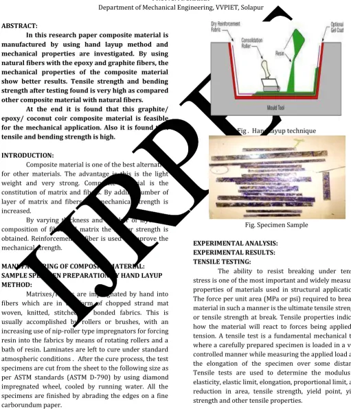
Matrixes/Resins are impregnated by hand into fibers which are in the form of chopped strand mat woven, knitted, stitched or bonded fabrics. This is usually accomplished by rollers or brushes, with an increasing use of nip-roller type impregnators for forcing resin into the fabrics by means of rotating rollers and a bath of resin. Laminates are left to cure under standard atmospheric conditions . After the cure process, the test specimens are cut from the sheet to the following size as per ASTM standards (ASTM D-790) by using diamond impregnated wheel, cooled by running water. All the specimens are finished by abrading the edges on a fine carborundum paper.
Fig . Hand layup technique
Fig. Specimen Sample
EXPERIMENTAL ANALYSIS: EXPERIMENTAL RESULTS: TENSILE TESTING:
VOLUME 3, ISSUE 3, Mar. -2017
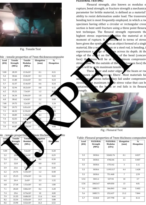
22 | P a g e Fig . Tensile Test
Table : tensile properties of 7mm thicknesscomposite
Load (KN)
Tensile Strength
(MPa)
Tensile Modulus
(MPa)
Elongation (mm)
% Elongation
5.00 28.39 13.9x10³ 0.1 0.21
5.4 30.66 13.8x10³ 0.3 0.22
5.6 31.80 13.6x10³ 0.4 0.23
5.7 32.37 13.4x10³ 0.6 0.24
5.8 32.94 10.2x10³ 0.8 0.32
6.2 35.21 7.3x10³ 1.2 0.48
6.4 36.34 5.04x10³ 1.8 0.72
6.8 38.62 4.3x10³ 2.2 0.88
7.00 39.75 3.2x10³ 3.1 1.24
7.00 39.75 3.01x10³ 3.3 1.32
7.1 40.32 2.19x10³ 4.6 1.84
7.2 40.89 1.23x10³ 8.3 3.32
7.4 42.03 1.05x10³ 10 4.00
7.6 43.16 0.963x10³ 11.2 4.48 7.9 44.87 0.919x10³ 12.2 4.88
Table : tensile properties of 10mm thickness composite
Load (KN)
Tensile Strength
(MPa)
Tensile Modulus
(MPa)
Elongation (mm)
% Elongation
5.00 20.00 7.6x10³ 0.1 0.28
5.2 20.8 7.5x10³ 0.3 0.29
5.4 21.6 7.3x10³ 0.6 0.30
5.7 22.8 7.1x10³ 0.8 0.32
5.9 23.6 5.9x10³ 1.0 0.40
6.2 24.76 5.16x10³ 1.2 0.48
6.3 25.15 3.93x10³ 1.6 0.64
6.6 26.4 2x10³ 3.3 1.32
6.8 27.18 1.51x10³ 4.5 1.80
7.1 28.20 0.86x10³ 8.2 3.28
7.4 29.6 0.74x10³ 10 4.00
7.9 31.55 0.68x10³ 11.6 4.64 8.2 32.54 0.55x10³ 14.7 5.88 8.6 33.90 0.52x10³ 16.3 6.52
FLEXURAL TESTING:
Flexural strength, also known as modulus of rupture, bend strength, or fracture strength a mechanical parameter for brittle material, is defined as a material's ability to resist deformation under load. The transverse bending test is most frequently employed, in which a rod specimen having either a circular or rectangular cross-section is bent until fracture using a three point flexural test technique. The flexural strength represents the highest stress experienced within the material at its moment of rupture. It is measured in terms of stress, here given the symbol.When an object formed of a single material, like a wooden beam or a steel rod, is bending, it experiences a range of stresses across its depth. At the edge of the object on the inside of the bend (concave face) the stress will be at its maximum compressive stress value. At the outside of the bend (convex face) the stress will be at its maximum tensile value.
These inner and outer edges of the beam or rod are known as the 'extreme fibers'. Most materials fail under tensile stress before they fail under compressive stress, so the maximum tensile stress value that can be sustained before the beam or rod fails is its flexural strength.
Fig : Flexural Test
Table :Flexural properties of 7mm thickness composites
Load (KN)
FLEXURAL Strength
(MPa)
FLEXURAL Modulus
(GPa)
Elongation (mm)
% Elongation
5.5 3030.6 52602.76 0.1 0.037
5.5 3030.6 4782.06 1.1 0.407
5.5 3030.6 1753.42 3 1.11
5.5 3030.6 1195.517 4.4 1.628
5.5 3030.6 751.468 7 2.59
5.52 3041.6 527.94 10 3.7
5.56 3063.67 409.050 13 4.81
5.6 3085.71 366.843 14.6 5.402
5.6 3085.71 252.637 21.2 7.844
VOLUME 3, ISSUE 3, Mar. -2017
23 | P a g e Table :Flexural properties of 10mm thickness
composites
FINITE ELEMENT ANALYSIS: FEA RESULT:
SOLUTION USING ANSYS:
1) ANSYS is finite element analysis software which enables engineers to perform the following tasks: 2) Build computer models or transfer CAD models of structures, products, components or systems.
3) Apply operating loads or other design performance conditions.
4) Study physical responses such as stress levels, temperature distribution or electromagnetic field. 5) Do prototype testing in environments where it otherwise would be undesirable or impossible.
6) The ANSYS program has a comprehensive graphical user interface (GUI) that gives users easy, interactive access to program functions, commands, documentation and reference material. A menu system helps users navigate through the ANSYS program.
7) Users can input data using a mouse, a keyboard, or a combination of both
ANALYSIS OF COMPOSITE MATERIAL BY USING ANSYS:
1) The solid model of composite material is created in CATIA V5. It is is a feature based modeling (FBM) software. Many CAD packages use FBM method. It is easy and gives model tree for completed part, so that modification at any point at any branch can be passed through whole model.
2) Thus FBM is suited for parameterization of model. It will be helpful to generate similar models from existing one just by changing the parameter values.
3)It is proposed to use FBM using CATIA V5 because of its user friendly and availability of parametric functions. 4)The fig shows the specimen of composite model in CATIA V5
Fig : CAD model of specimen of composite
The CAD model of composite specimen was saved in .igs format for importing it into ANSYS
workbench for the analysis purpose.
The material used for the composite specimen is epoxy/graphite/coconut coir which isotropic behavior.
ELEMENT TYPE SELECTION: HEXAHEDRON TYPE: HEXAHEDRON ELEMENT DESCRIPTION:
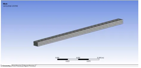
In computational solutions of partial differential equations, meshing is a discrete representation of the geometry that is involved in the problem. Essentially, it partitions space into elements (or cells or zones) over which the equations can be approximated. Zone boundaries can be free to create computationally best shaped zones, or they can be fixed to represent internal or external boundaries within a model. The basic 3-dimensional element is the tetrahedron, quadrilateral pyramid, triangular prism, and hexahedron. They all have triangular and quadrilateral faces.
A hexahedron, a topological cube, has 8 vertices, 12 edges, bounded by 6 quadrilateral faces. It is also called a hex or a brick. For the same cell amount, the accuracy of solutions in hexahedral meshes is the highest. The pyramid and triangular prism zones can be considered computationally as degenerate hexahedrons, where some edges have been reduced to zero. Other degenerate forms of a hexahedron may also be represented.
Fig : Meshed Geometry
Load (KN)
FLEXUR AL Strength
(MPa)
FLEXURAL Modulus
(GPa)
Elongation (mm)
% Elongation
5.2 1404 1698.66 0.1 0.037
5.28 1425.6 862.39 0.2 0.074
5.28 1425.6 143.73 1.2 0.44
5.3 1431 108.2 1.6 0.592
5.3 1431 52.4 3.3 1.22
5.3 1431 38.4 4.5 1.665
5.3 1431 32.66 5.3 1.961
5.3 1431 28.38 6.1 2.257
5.34 1441.8 27.25 6.4 2.368
5.36 1447.2 21.35 8.2 3.034
5.4 1458 17.63 10 3.7
5.4 1458 17.126 10.3 3.811
5.42 1463.4 15.26 11.6 4.292
5.42 1463.4 14.878 11.9 4.403
5.46 1474.2 12.133 14.7 5.439
5.48 1479.6 11.25 15.9 5.883
5.5 1485 11.022 16.3 6.031
5.52 1490.4 10.9951 16.4 6.068
VOLUME 3, ISSUE 3, Mar. -2017
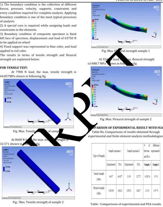
24 | P a g e 1) The boundary condition is the collection of different
forces, pressure, velocity, supports, constraints and every condition required for complete analysis. Applying boundary condition is one of the most typical processes of analysis.
2) A special care is required while assigning loads and constraints to the elements.
3) Boundary condition of composite specimen is fixed left face of specimen, displacement and load of 63750 N to be applied on wheel
4) Fixed support was represented in blue color, and load applied in red color.
The results in terms of tensile strength and flexural strength are explained below:
FOR TENSILE TEST:
At 7900 N load, the max. tensile strength is 44.857MPa shown in following fig.
Fig :Max. Tensile strength of sample 1
At 8600 N load, the max. tensile strength is 32.571 shown in following fig.
Fig : Max. Tensile strength of sample 2
FOR FLEXURAL TEST:
At 5700 N load, the max. Flexural strength is 3062.4 MPa shown in following fig
Fig :Max. Flexural strength sample 1
At 5540 N load, the max. flexural strength is1488.7 MPa shown in following fig
Fig :Max. Flexural strength of sample 2
COMPARISON OF EXPERIMENTAL RESULT WITH FEA:
Table No. Comparisons of results obtained through experimental and finite element analysis methodologies:
Table : Comparisons of experimental and FEA results
VOLUME 3, ISSUE 3, Mar. -2017
25 | P a g e
RESULT AND DISCUSSION:
Finite element analysis results of composite testing are discussed on the basis of tensile and flexural strength is as follows:
MAXIMUM TENSILE AND FLEXURAL STRENGTH:
1) For tensile test (sample 1) max. load is 7.9 KN and tensile strength is 44.857 MPa.
2) For tensile test (sample 2) max. load is 8.6 KN and tensile strength is32.571 MPa .
3) For flexural test (sample 1) max. load is 5.7 KN and flexural strength is 3062.4 MPa .
4) For flexural test (sample 2) max. load is 5.54 KN and flexural strength is 1488.7 MPa
CONCLUSION:
The results of present study showed that a useful composite with good properties could be successfully developed using coconut coir fiber and graphite as reinforcing agent for the epoxy resin matrix. From this, several conclusions can be drawn regarding to mechanical properties of composite to the effect of fiber proportion, namely tensile, flexural properties.
As the epoxy resin reinforced with coir and graphite fibers, the tensile strength and flexural strength was high for 7mm composite with fibers proportion 30% coir and 15% graphite. 10mm composite shows less tensile and flexural strength where fiber proportion is 40% coir and 20% graphite. The young’s modulus of 7mm composite was good because there is a great bond between the matrix and resin material, and have a more load carrying capacity when compared with other 10mm thick composite and it considered as the optimum thickness and fiber proportion. Presence of optimum fiber proportion and composite thickness in the composite increased the young’s modulus and strength. This was because of the presence of great bond between the fiber and the matrix material in the case of 7mm fiber reinforced composite which transferred more load. This material shows very high flexural strength and flexural modulus as compared to other composite materials used for preparing panels of automotive instruments panel. Because of high flexural strength this material is good for automotive instrument panel as compared to other composite like, like Glass fiber and banana fiber with epoxy resin, Coconut shell and palm fruit, Glass & graphite with epoxy, Epoxy with bark cloth, Abaca fiber with epoxy etc.
By FEA analysis, maximum tensile strength for 7mm composite is 44.857 MPa. Maximum tensile strength for 10mm composite is 32.571 MPa .
By FEA analysis, maximum flexural strength for 7mm composite is 3062.4 MPa. Maximum flexural strength for 10mm composite is 1488.7 MPa .
REFERENCES:
1) Samson Rwawiire, BlankaTomkova , Jiri Militky , Abdul Jabbar ,BanduMadhukar Kale: “Development of a biocomposite based on green epoxy polymer andnatural cellulose fabric (bark cloth) for automotive instrument panel applications. 2015 Elsevier Ltd.
2) Rajendra Kumar,Tejeet Singh and Harwindersinh-“Natural Fibers Polymeric Composites with Particulate Fillers – A review report”, International Journal of Advanced Engineering Research and Applications ISSN (online): 2454-2377 Vol. – 1, Issue – 1 May – 2015.
3) D. Chandramohan& .K. Marimuthu– “a review on natural fibers. IJRRAS 8 (2) ● August 2011
4) PiyooshThori, Pawan Sharma, Manish Bhargava- “an approach of composite materials in industrial
machinery: advantages, disadvantages and
applications .IJRET eISSN: 2319-1163 | pISSN: 2321-7308
5) ahmedelmarakbi: advanced composite materials for auto motive applications is bn: 978-1-118-42386-8. 6) Maya Jacob John, Rajesh D. Anandjiwala-“ Recent
developments in chemical modification and
characterization of atural fiber‐reinforced
composites”,
researchgate.net/publication/227629263
7) Majid Ali: “Coconut Fibre – A Versatile Material and its Applications in Engineering Second International Conference on Sustainable Construction Materials and Technologies June 28 - June 30, 2010, University Politecnic adelle Marche, Ancona, Italy. 8) G.Rathnakar1 , Dr. H.K.Shivanand-“ Fibre Orientation
and Its Influence on theFlexural Strength of Glass fibre and Graphitefibre reinforced polymer composites. IJIRSETVol. 2, Issue 3, March 2013.
9) S. I. Durowaye1,*, G. I. Lawal1, M. A. Akande1, V. O. Durowaye2 – “Mechanical Properties of Particulate Coconut Shell and Palm Fruit Polyester Composites” , International Journal of Materials Engineering 2014, 4(4): 141-147