Mahua Biodiesel: A Future Alternative Fuel
Jakeer Husain Rahena Anjum
Department of Science & Humanities Department of Science & Humanities Farah Institute of Technology, Chevella, JNTUH, India -
501503
Farah Institute of Technology, Chevella, JNTUH, India - 501503
Nagalli Raghu Jai Sagar
Department of MechanicalEngineering Department of MechanicalEngineering Farah Institute of Technology, Chevella, JNTUH, India –
501503
Farah Institute of Technology, Chevella, JNTUH, India - 501503
Bushra Anjum Department of Physics
Gulbarga University Gulbarga 585106 Karnataka, India
Abstract
All natural reserves being depleted fast due to over consumption. Almost 90% of the world’s energy needs are met by the non-renewable sources of energy like coal, oil and natural gas. This is of concern globally as the future generations would definitely be at threat. And this is the ringing alarm bell. The results of performance characteristics of a single cylinder, four stroke, computerized Kirloskar make CI Engine by using mahua (Madhuca indica) oil biodiesel and its 60% blend with diesel fuel have been presented in this paper. Short-term engine performance tests were conducted using diesel, mahua oil biodiesel and its 60% blend.
Keywords: Biodiesel, Physiochemical properties, Mahua bio-diesel
_______________________________________________________________________________________________________
I. INTRODUCTION
Reducing transportation emissions is one of the most vital steps in fighting global warming and solutions to the transportation problem are already available. Our nation needs to shift away from fossil fuel-powered vehicle dependence and the suburban sprawl that accompanies it and toward alternative fuels, alternative and public transportation, and better land-use patterns to begin reducing our country’s total vehicle miles travelled each year. The Centre is working on all aspects of the transportation problem, from advocating for increased fuel economy standards to challenging new sprawl developments, using existing laws and working for new regulations to restrict vehicle emissions and take advantage of alternative-fuels technology for the benefit of the planet. [1]
Biodiesel
Biodiesel is monoalkyl ester of long chain fatty acids produced from the transesterification reaction of vegetable oil with alcohol in the presence of catalyst & can be used as fuel. Biodiesel is made from animal fats or vegetable oils, renewable resources that come from plants such as, soybean, sunflowers, corn, olive, peanut, palm, coconut, safflower, canola, sesame, cottonseed, etc. Once these fats or oils are filtered from their hydrocarbons and then combined with alcohol like methanol, biodiesel is brought to life from this chemical reaction. These raw materials can either be mixed with pure diesel to make various proportions, or used alone[2-4]
Mahua
II. EXPERIMENTAL METHODS: PROCESS OF EXTRACTING (SEED TO POWER)
Extraction of oil:
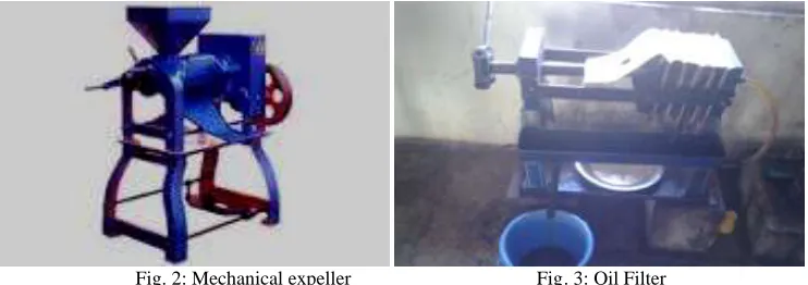
The extraction of oil from Mahua seeds was done by using mechanical expeller using methanol as solvent.
Mechanical Expeller (production scale):
The Steps are as follows
1) Seeds are crushed using mechanical expeller to get oil. (Mechanical expeller is of capacity 30kg/hr, 3passes). 2) For a batch 5kg of seeds are taken to crush, each batch of seeds passed 5times to obtain complete oil. 3) Oil obtained was collected in a glass reagent container by filtering it with filters.
4) Filtered oil left for 10-12hrs for settling of minute dust particles. 5) After filter and settling, oil stored in a reagent glass bottles.
Seed (Clean dry seeds)
Oil Cake
Expeller
Filter
Filtered Oil
Alcohol (CH3OH)
+
Catalyst (NaOH)
Glycerin
Transesterification
Purification
Biodiesel
Washing
Soap/pears/candle
Drying
Pure Biodiesel
Fig. 2: Mechanical expeller Fig. 3: Oil Filter
III. EXPERIMENTAL SET-UP
The various components of experimental set up are described below. Shows Fig. shows the photograph of the experimental set up. The important components of the system are
The Engine:
The Engine chosen to carry out experimentation is a single cylinder, four stroke, vertical, water cooled, direct injection computerized Kirloskar make CI Engine. This engine can withstand higher pressures encountered and also is used extensively in agriculture and industrial sectors. Therefore this engine is selected for carrying experiments.
Dynamometer:
The engine has a DC electrical dynamometer to measure its output. The dynamometer is calibrated statistically before use. The dynamometer is reversible i.e., it works as monitoring as well as an absorbing device. Load is controlled by changing the field current. Eddy-Current Dynamometer's theory is based on Eddy-Current (Fleming's right hand law). The construction of eddy-current dynamometer has a notched disc(rotor) which is driven by a prime mover(such as engine, etc.) and magnetic poles(stators) are located outside with a gap. The coil which excites the magnetic pole is wound in circumferential direction. When current runs through exciting coil, a magnetic flux loop is formed around the exciting coil through stators and a rotor. The rotation of rotor produces density difference, then eddy-current goes to stator. The electromagnetic force is applied opposite to the rotational direction by the product of this eddy-current.
Smoke meter:
Smoke measurement is made using an “OPAX2000II/DX200P” of Neptune Equipment Pvt. Ltd. Ahmedabad. The measurement is based on the principle of light absorption by particle. Photo electronic smoke detection is based on the principle of optical detection. It is also known as the "scattered" light principle. An alarm condition occurs when smoke particles. enter the light path and a part of the light is "scattered" by reflection and refraction onto a sensor. This type of detector is best for areas where dense smoke may occur, as in ductwork. The equipment allows test on a continuous mode, average and peak levels. The measured operating values are shown as three digital either in light absorption coefficient that is in ABS „K‟ units from 0.00 to 9.99 are in Bosch units (or) in percentage from 0% to 99.9%.The measurements are made in Bosch units at continuous mode. Fig. shows the actual photo of smoke meter attached to the engine at the exit.
Exhaust Gas Analyzer:
All emissions like Carbon monoxide, Carbon dioxide, Un-Burnt Hydrocarbons, Nitrogen oxide and unused oxygen are found in 5 gas emission analyzer of model “5G -10 , PLANET EQUIPMENT” is used. In this cable one end is connected to the inlet of the analyzer and the other end is connected at the end of the exhaust gas outlet. Continuous charging of the analyzer is essential to work in an effective way .Fig. show the actual photos of Exhaust Gas Analyzer attached to engine at the exit. The measuring method is based on the principle of light absorption in the infrared region, known as "non-dispersive infrared absorption". The broadband infrared radiation produced by the light source passes through a chamber filled with gas, generally methane or carbon dioxide. This gas absorbs radiation of a known wavelength and this absorption is a measure of the concentration of the gas. There is a narrow bandwidth optical filter at electric detector.
IV. EXPERIMENTAL PROGRAMME
Fig. 4: Experimental set up of computerized C.I. Engine with smoke meter
For 60% Biodisel
Fig. 5: Experimental set up of computerized C.I. Engine with smoke meter Graph no IP, BP & FP
V. CALCULATED RESULT DATA
Speed (rpm) Load (kg) IP (kW) BP (kW) FP (kW) 3035.00 -0.12 56.88 -0.08 56.96 3029.00 7.18 64.55 4.69 59.86 3007.00 13.87 66.38 9.00 57.38 3028.00 20.96 72.97 13.69 59.28 3038.00 28.16 75.35 18.46 56.89
Torque (Nm) BP (kW) FP (kW) IP (kW) BMEP (bar) IMEP (bar) BTHE (%) ITHE (%) Mech Eff. (%) -0.24 -0.08 56.96 56.88 -0.02 16.01 -0.33 245.96 -0.13 14.79 4.69 59.86 64.55 1.32 18.20 12.88 177.23 7.27 28.58 9.00 57.38 66.38 2.56 18.86 19.96 147.19 13.56 43.17 13.69 59.28 72.97 3.86 20.58 24.66 131.46 18.76 58.02 18.46 56.89 75.35 5.19 21.19 27.52 112.35 24.50
VI. CONCLUSION
ACKNOWLEDGMENTS
The First author is working as faculty in the Department of S&H and grateful to the management of Farah Institute of Technology, Chevella for the financial support in the research work.
REFERENCES
[1] Kaygusuz K and Kaygusuz A 2002, Renewable Energy, Volume 25, Issue 3, pp 431-453, doi: 10.1016/S09601481(01)00075-1. [2] Maishanu SM, Musa M and Sambo AS, 1990, Nigerian Journal of Solar Energy, 9: 183-194.
[3] Buren AV, 1979, a Chinese Biogas Manual. Intermediate Technology Publications Ltd. 11- 24. [4] Arvanitoyannis IS, Kassaveti A and Stefanatos S, 2007, Int. J. Food Sci. Tech. 42 (7): 852 – 867. [5] Bhat P.R., Chanakya H.N. and Ravindranath N.H., 2001, J. Energy Sustainable Dev. 1:39 –41.