Veerappan et al. World Journal of Engineering Research and Technology
COMPARISON OF THE SPEED AMONG DIGITAL, OPTICAL AND
HYBRID IMAGE PROCESSORS FOR REAL TIME APPLICATIONS
Dr. J. Veerappan*1 and Dr. R. Ganesan2 1
Professor, Department of ECE, Vel Tech High Tech, Chennai. 2
Professor, Department of EIE, Saveetha Engineering College, Chennai.
Article Received on 30/10/2019 Article Revised on 20/11/2019 Article Accepted on 10/12/2019
ABSTRACT
Selection of a conventional Digital Image Processor (DIP) / Optical
Image Processor (OIP) / Hybrid Image Processor (HIP) depends upon
its processing speed. The processing speed is a major constraint to
increase the input frame rate which affects the output quality of the real
time processing. In this paper, the processing time and maximum input frame rate for real
time operation of DIP, OIP and HIP are found out and compared. It is inferred that both OIP
and HIP are highly applicable for real time processing whereas DIP is applicable only after
reducing their input frame rate.
KEYWORDS: DIP, HIP, OIP and Real-time processing.
1. INTRODUCTION
In image processing, the emphasis must be given to the term, “Real Time Applications”. If
any process is completed within the rate of incoming signal, then it is said to be suitable for
real time applications.[1-3] The frequency domain Image processors may be viewed in three
broad senses viz, Optical domain Image Processor (OIP) using optics,[4,5] Digital domain
Image Processor (DIP) using computers.[6,7] and Hybrid Image Processor (HIP) using both
optics and computers.[8,9]
At present, the Digital domain Fourier Transform (DFT) and Inverse Digital domain Fourier
Transform (IDFT) in DIP consume much time, in signal/image processing, is a
World Journal of Engineering Research and Technology
WJERT
www.wjert.org SJIF Impact Factor: 5.924
*Corresponding Author Dr. J. Veerappan
Professor, Department of
ECE, Vel Tech High Tech,
constraint.[10,11] The presence of inherent errors due to sampling, quantizing and aliasing
process.[12] in DFT also affects the quality of the output.
The salient feature of Optical domain Fourier Transform (OFT) in OIP is that it produces
spectra of given image within a few nanoseconds whereas DFT in DIP produces the same in
the order of milliseconds. This is because OFT is a simultaneous process rather than DFT
which is under pixel by pixel processing.[13] i.e., the spectra of the entire image can be
obtained by manipulating the pixels simultaneously which is in a single step so that entire
processing speed of OIP is similar to light propagation speed which is higher than real time
video frame rate (25 Frames Per Second (FPS)). But the real time application of DIP is only
possible by reducing their input frame rate according to their processing speed.[14]
Hybrid Image Processor (HIP) is one of the high processing speed real time image processors
which are nothing but replacement of DFT by OFT in DIP.[15] A survey of literature reveals
that there is no work carried out on the comparison of the speed analysis among this three
image processors in a nutshell form. Hence in this paper it is tried to compare and find out the
suitable processor to produce the output with enhanced quality under real time processing.
The real image processing of these three are compared. It is found that the HIP is highly
applicable and more suitable for all types of real time image processing than the others.
2. RESULTS AND DISCUSSION
Analysis of processing time and speed of DIP: In DIP,[16] the DFT algorithm forms the spectraG(u,v), which are the Fourier transform of the object imageg(x,y). The filter section
contains the complex valued transfer functionH(u,v). The complex amplitude of the signal
from the filter isG(u,v)H(u,v); IDFT algorithm forms the inverse transform of this function
to produce the output image. The output image is then viewed using a real time digital
display (LCD display).
The simulated output obtained at each stage of DIP block for a given image (in 256256
size),[17] is given in fig.1. The processing time and speed for the same are tabulated in
Table 1.
Table 1: Processing time and speed of each block in DIP.
DIP sections Processing time/frame
in ms
Processing speed (Frames Per Second (FPS).
Digital Camera 40 25
DFT 78 12.8
Filter spectrum- generation 4 250
Processing 10 100
IDFT 62 16.1
Digital Display- (LCD projector) 40 25
Analysis of processing time and speed of OIP: According to Scalar and Fraunhofer diffraction theories,[18] in the OIP setup, OFT lens (focal length of about 40cm) forms the
spectra G(u',v')in its back focal plane, which is the Fourier transform of object
imageg(x,y). The spatial filterH(u,v) placed at the back focal plane of the OFT lens and
the spectra propagating away from the spatial filter isG(u',v')H(u,v). The OIFT lens forms
the inverse transform of this function to produce output image in its back focal plane. This
processed image can be viewed or recorded through Digital Camera with display, which is
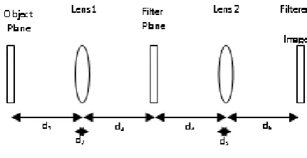
kept at the back focal plane of the OIFT lens. The schematic diagram of OIP is given in fig.2.
Figure 2: Schematic diagram of OIP.
Using the fig 2, the total time Tof the entire OIP for an image frame may be formulated by
1 1 2 3 4 2 5 6
1
d d n d d d n d c
T ……. (1)
Where c is the velocity of light in air (3108ms1.) and, n1 and n2 are the refractive indices
and n1n2 n1.5, then the processing time and speed for each block in OIP, were
evaluated and presented in Table 2.
Table 2: Processing time and speed of OIP.
OIP sections Processing time per frame (ns) Processing speed (FPS).
OFT 3.3 8
10 3
Filtering negligible Infinity
OIFT 3.3 8
10 3
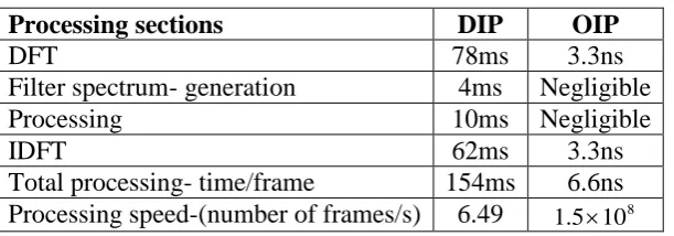
Motivations of HIP: From the Table 1, the DIP processing speed for a given frame (6.5FPS) is evaluated from the total processing time (154ms) shown in Table 3. Under
this speed DIP is applicable to some real time (170ms/frame) applications by reducing their
input frame rate (6 FPS). This speed lies approximately between 5FPS and 12FPS. It
depends on the selection of an image to be processed, selection of computer and the selection
of the software etc.[19] However the Field-Programmable Gate Array (FPGA) based digital
camera is required to supply the input with suitable frame rate.[20]
Table 3: Processing time and speed of DIP and OIP.
Processing sections DIP OIP
DFT 78ms 3.3ns
Filter spectrum- generation 4ms Negligible
Processing 10ms Negligible
IDFT 62ms 3.3ns
Total processing- time/frame 154ms 6.6ns Processing speed-(number of frames/s) 6.49 8
10 5 .
1
Using the Table 2 the entire processing time (Table 3) of OIP can be calculated . It is in the
order of nanoseconds, and therefore the speed of OIP is in the order of 108FPS which is
highly exceeds the real time video frame rate (25FPS) and also very much higher than the
processing speed of DIP. Thus, it proves that OIP is highly suitable and applicable for real
time image processing. However OIP has certain drawbacks also.[5] i) It requires certain
manual operations to be performed during the filtering section. ii) It is highly difficult to
perform spatial domain image processing techniques such as edge detection, and pixel
extraction etc.
Combining the advantages of both DIP and OIP, a new image processing technique is
developed in which DFT is replaced by OFT in DIP.[21] This replacement develops a new
DFT in DIP by OFT would not be much expensive and also it can cut processing time of DIP
significantly.
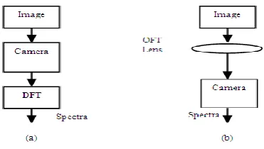
Analysis of processing time and speed of HIP: In HIP the concept of modification required for the replacement of DFT by OFT in DIP has been shown in figures 3(a) and 3(b). In DIP
(figure 3a) the given image is converted to electrical and then spectra of the image are
obtained by DFT. In HIP (figure 3b), the spectra of the given image are obtained by OFT lens
which are then converted into electrical signal using a digital camera.
The processing time and speed of HIP (Table 4) can be evaluated from DIP and OIP (Table
3). From Table 4, the entire processing speed (13FPS) of HIP is (higher than DIP) still
lower than real time input frame rate. If the high (double) speed computer [22] is used in HIP,
it is enough to increase (double) the processing speed (26FPS) which is closer to the real
time video frames rate. But the high (double) speed DIP (computer with dual processors-
1GB RAM etc) has minimum processing time (78ms) and then it can be used for some real
time applications with the maximum input frame rate (12FPS) which is still lower than real
time video frame rate. So, FPGA digital camera is always required for DIP real time
operations.[23] However some additional hardwares (Fig 4) are required in HIP for
replacement of DFT by OFT.[24]
Table 4: Processing time and speed of DIP, OIP and HIP.
Processing sections DIP OIP HIP
DFT 78ms 3.3ns 3.3ns
Filter spectrum- generation 4ms Negligible 4ms
Processing 10ms Negligible 10ms
IDFT 62ms 3.3ns 62ms
Total processing time/frame 154ms 6.6ns 76ms Processing speed (number of frames/s) 6.49 8
10 5 .
1 13.16
Comparison of DIP, OIP and HIP
Figure 5 shows the comparison of real time image processing of DIP, HIP1 (normal speed)
and HIP2 (double speed). It is a graph between minimum real time/frame (fig2a) of DIP,
HIP1 and HIP2 which are 157, 83 and 17 ms respectively versus the maximum frame rate for
real time operation of DIP, HIP1 and HIP2 which are 6.5, 13 and 26 FPS respectively. The
HIP2 ensures the high quality output because of its allowable input frame rate is closer to real
time video frames rate.
3. EXPERIMENTAL
The simulation of DIP was performed using Pentium – IV with 256 MB RAM using
MATLAB software. The processing time was carried out using MATLAB timer which is
initiating at the beginning and stopping of it at the end of the block. Speed was evaluated
from the processing time (Table 3).
In the experimental setup (Fig 4) of HIP (based on the OIP which is constructed at
Department of Physics, Sri Sathya Sai Institute of Higher Learning (Deemed University),
Prasanthi Nilayam, Andhra Pradesh, India) the digital camera 1 (Product Dimensions is 25 x
20 x 25 inches and Record & Display at 120 FPS) converts the object image g(x,y) to
electrical and then it is supplied to Spatial Light Modulator (SLM). Here the image (1cm2) is
illuminated by the collimated light beam obtained from the set of Helium-Neon LASER
( 632.8nm andP10mW ), Neutral Density Filter (NDF), Spatial Filter, Collimating
Lens, an Aperture and mirror [figure 3] so that the information of the object image gets
impressed on the beam after it passes through the SLM. The spectra G(u',v')of the image
obtained by OFT lens are converted to digital by real time camera 2. Then it is applied to the
computer filtering section, which contains the complex valued filter transfer functionH(u,v).
algorithm forms the inverse transform of this function to produce the output image. The
output image is then viewed through a real time Digital display.
Figure 5: Comparison of DIP and HIP.
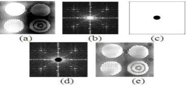
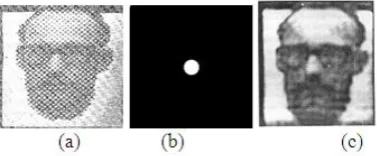
Figure 6: (a) Image, (b) filter (low pass) (c) filtered image.
The digital cameras in this system can only record the amplitude or intensity information.[25]
The phase information needs to be recorded by the use of another reference wave front with
interference technique. However the absence of inherent errors due to sampling, quantizing
and aliasing process in OFT leads the quality of the output of HIP to get enhanced (fig 6).
HIP has been further enhanced by the introduction of various recent advanced techniques.[17]
like uni and multi-spectral imagery, beam pattern correction algorithm, edge detection
algorithm and Teslation algorithm etc. as in DIP.
4. CONCLUSION
We have identified that the entire processing time/frame of OIP is in the order of
nanoseconds whereas in DIP and HIP it is in the order of milliseconds. The conventional DIP
is applicable to some real time applications only by reducing their input frame rate. From the
comparison among OIP, DIP and HIP, HIP ensures the high quality output because of its
allowable real time input frame rate.
5. ACKNOWLEDGEMENTS
We express our sincere thanks to Anna University, KLN College of Engineering, Sri Sathya
REFERENCES
1. T. Matsuyama and N. Ukita. Real-time multi target tracking by a cooperative distributed
vision system, proceeding of IEEE, 2012; 90(7): 1136- 1150.
2. Gulathi R R Television pictures-chapter2, Modern Television Practice, 2nd edition, New
age international (p) Ltd Publishers, 2014.
3. K. Oka , Y. Sato and H. Koike Real-time fingertip tracking and gesture recognition, IEEE
transactions on computer Graphics and Applications, 2012; 22(6): 64-71.
4. Brandley G.Boone, K. Oka Y. Sato, H. Koike, Real-time fingertip tracking and gesture
recognition, IEEE transactions on computer Graphics and Applications, 2018; 22(6):
64-71.
5. Joseph W. Goodman, Spatial filtering and optical information processing-chapter 7,
Introduction to Fourier Optics, pp141-198 McGraw Hill, 1968.
6. R.C. Gonzalez and R.E.Woods, Image enhancement in the frequency domain-chapter4,
Digital Image Processing, pp148-251, Pearson Education, INC, 2004.
7. Ad.C. Lucas, and R. Ernst, An image processor for digital film, IEEE International
Conference on Application-Specific Systems, Architecture Processors, ASAP, 2015; 219-
224.
8. Zhenyu He, Yuan Yan Tang, and Xinge You, A contourlet-based method for writer
identification, IEEE International Conference on Systems, Man and Cybernetics, 2015; 1:
364-368.
9. Salvador Bosch and Raul Tudela, Impact of the 2D structured noise in the post-processing
of hybrid optical-digital imaging systems, Proceedings of SPIE International Optical
Design Conference, 2016, 6342: 1-10.
10.B. Dale, M. Wendt and J.L. Duerk, A rapid look-up table method for reconstructing MR
images from arbitrary K-space trajectories, IEEE Transactions on Medical Imaging, 2012;
20(3): 207-217.
11.Fabin Shen and Anbo Wang, Fast-Fourier-transform based numerical integration method
for the Rayleigh-Sommerfeld diffraction formula, Applied Optics, 2016; 45(6):
1102-1110.
12.Satorius, E.H and Zhong Ye Channel modeling and simulation for mobile user objective
system (MUOS)--Part II: selective scintillation and terrestrial multipath fading, IEEE
International Conference on Communications, ICC, 2013; 03(5): 3511- 3518.
ppXVII-14.S.P.Monacos, R.K.Larn, A.A.Portillo, D.Q.Zhu, and G.G.Ortiz, Design of an
Event-Driven, Random-Access Windowing CCD-Based Camera, IPN Progress Report, 1998;
42-155.
15.Zhenyu He, Yuan Yan Tang and Xinge You A contourlet-based method for writer
identification IEEE International Conference on Systems, man and cybernetics, 2015
16.I.S. Uzun, A. Amira, and A. Bouridane, FPGA implementations of fast Fourier
transforms for real-time signal and image processing IEE Proceedings of Vision, Image
and Signal Processing, 2015; 152(3): 283- 296.
17.David G. Zawada, Image Processing of under water multispectral Imagery, IEEE Journal
of Oceanic Engineering, 2013; 28(4): 583-594.
18.Ting Chung and Partha.P.Banerjee, Single and double lens Image processing systems
chapter 5, Contemporary Optical Image Processing with MATLAB, pp133-169 Elesevier,
London, 2011.
19.Y.J.Ren, J.G.Zhu, X.Y. Yang and S.H. Ye The Application of Virtex-II Pro FPGA in
High- Speed Image processing Technology of Robot Vision Sensor Journal of Physics
Conference Series, 2016; 48(2006): 373-378.
20.Lucas, Ad.C. Ernst, R. An image processor for digital film 16th IEEE International
Conference on Application-Specific Systems, Architecture Processors, ASAP, 2015;
219- 224.
21.Keith Frampton, Hybrid Optical/Digital Processor for Radar imaging, Essex Corporation
HEPC, 2013; 1-33.
22.P.T. Kumar, Performance Analysis of Intel Core 2 Duo Processor Electronic Thesis and
Dissertation Louisiana state University, 2017.
23.C.T.Johnston, D.G.Bailey and P.Lyons A Visual Environment for Real-Time Image
Processing in Hardware (VERTIPH) EURASIP, Journal on Embedded Systems, 2016;
1-8.
24.R.Sai Santosh Kumar, A Project report on Edge-Enhancement Technique in Optical
Fourier Processing: Applications to Medical Images, Dept of Physics, Sai Sathya Sai
Institute of Higher Learning (Deemed University), Prasanthi Nilayam, Andhra Pradesh,
2014; 1-65.
25.S Prapayasatok, A Janhom, K Verochana and S Pramojanee, Digital camera resolution