Gurpreet et al. World Journal of Engineering Research and Technology
PERFORMANCE ENHANCEMENT IN IMAGE USING NOVEL EDGE
DETECTION ALGORITHM
Gurpreet Kaur* and Er. Manreet Kaur
1
M.Tech Scholar Department of Computer Sc. & Engg., St. Soldier Institute of Engg. &
Technology, Near NIT, Jalandhar (Punjab)-144011.
2
Assistant Professor, Department of Computer Sc. & Engg., St. Soldier Institute of Engg. &
Technology, Near NIT, Jalandhar (Punjab)-144011.
Article Received on 08/10/2018 Article Revised on 29/10/2018 Article Accepted on 19/11/2018
ABSTRACT
Edge detection is one of the most important tasks in digital image
processing. Edges characterize the boundaries i.e. an edge is a
boundary between an object and background. Edges in the images are
the area with strong intensity contrasts- a jump in intensity from one
pixel to the next. Edge detection significantly reduces the amount of
data and filters out useful information, while preserves the important
structural properties in an image. Therefore edge Detection refers to the process of
identifying and locating sharp discontinuities in an image. The discontinuities are abrupt
changes in pixel intensity which characterize boundaries of objects in a scene. The shape of
the edges in images depends on many parameters: the geometrical and optical properties of
the object, the illumination conditions and the noise level in the images. The goal of edge
detection in a digital image is to determine the frontiers of all represented objects, based on
automatic processing of the gray level information in each present pixel. Classical methods of
edge detection involve convolving the image with an operator (a 2-D filter), which is
constructed to be sensitive to large gradients in the image while returning values of zero in
uniform regions. There is an extremely large number of edge detection operators available,
each designed to be sensitive to certain types of edges. The goal of our research work is to
study various edge detection techniques, compare those techniques and find the efficient
method which has better results in the output image.
World Journal of Engineering Research and Technology
WJERT
www.wjert.org
SJIF Impact Factor: 5.218*Corresponding Author
Gurpreet Kaur
KEYWORDS: RGB, CCD, LoG.
INTRODUCTION
A digital image is a representation of a two-dimensional image as a finite set of digital
values. In image processing, the digitization process includes sampling and quantization of
continuous data. The sampling process samples the intensity of the continuous-tone image,
such as a monochrome, color or multi-spectrum image, at specific locations on a discrete
grid. The grid defines the sampling resolution. The quantization process converts the
continuous or analog values of intensity brightness into discrete data, which corresponds to
the digital brightness value of each sample, ranging from black, through the grays, to white.
A digitized sample is referred to as a picture element, or pixel.
Brief review of Edge Detection
Unlike the real world, images do not have edges. An edge is sharp change in intensity of an
image But, since the overall goal is to locate edges in the real world via an image, the term
edge detection is commonly used. An edge is not a physical entity, just like a shadow. It is
where the picture ends and the wall starts, where the vertical and the horizontal surfaces of an
object meet. If there were sensor with infinitely small footprints and zero-width point spread
functions, an edge would be recorded between pixels within in an image. In reality, what
appears to be an edge from the distance may even contain other edges when looked close-up.
The edge between a forest and a road in an aerial photo may not look like an edge any more
in a image taken on the ground. In the ground image, edges may be found around each
individual tree. If looked a few inches away from a tree, edges may be found within the
texture on the bark of the tree. Edges are scale-dependent and an edge may contain other
edges, but at a certain scale, an edge still has no width. If the edges in an image are identified
accurately, all the objects are located and their basic properties such as area, perimeter and
shape can be measured. Therefore edges are used for boundary estimation and segmentation
in the scene. Since computer vision involves the identification and classification of objects in
Types of Edges
Figure 1: Types of Edges (a) Sharp step (b) Gradual step (c) Roof (d) Trough. A Sharp Step, as shown in Figure 1.2(a), is an idealization of an edge. Since an image is
always band limited, this type of graph cannot ever occur. A Gradual Step, as shown in
Figure 1.2(b), is very similar to a Sharp Step, but it has been smoothed out. The change in
intensity is not as quick or sharp. A Roof, as show in Figure 1.2(c), is different than the first
two edges. The derivative of this edge is discontinuous. A Roof can have a variety of
sharpness, widths, and spatial extents. The Trough, also shown in Figure 1.2(d), is the inverse
of a Roof. Edge detection is very useful in a number of contexts. Edges characterize object
boundaries and are, therefore, useful for segmentation, registration, and identification of
objects in scenes.
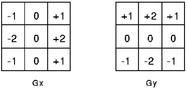
Sobel Operator
The operator consists of a pair of 3×3 convolution kernels as shown in Figure 1.6(a). One
kernel is simply the other rotated by 90°.
These kernels are designed to respond maximally to edges running vertically and horizontally
relative to the pixel grid, one kernel for each of the two perpendicular orientations. The
gradient component in each orientation (call these Gx and Gy). These can then be combined
together to find the absolute magnitude of the gradient at each point and the orientation of
that gradient. The gradient magnitude is given by:
Typically, an approximate magnitude is computed using:
which is much faster to compute.
The angle of orientation of the edge (relative to the pixel grid) giving rise to the spatial
gradient is given by:
Objectives of the Work
Our first major objective is to understand types of edges, its features and how we to detect
them. Thus we study the various existing edge detecting methods in detail. An exhaustive
literature survey is carried out to meet the objective.
Our next objective is to select the theoretical best and feasible method and try to
implement it under the VC++ environment for tiff file format.
The performance of the method implemented is measured and analyzed.
Our final goal is to modify the existing method to improve the results.
METHODOLOGY
The step-by-step methodology to be followed for detecting edges.
a) First of all a collection of gray scale images is collected.
b) The various edge detection filters are implemented in VC++.
c) Advantages and disadvantages of the methods will be analyzed.
d) Results achieved after the execution of program will be compared with the other methods.
e) We have several parameters to compare the edge detection methods.
f) We can try other parameters also to verify the method.
g) For example the processing speed of the method can be compared with other methods.
Suppose we have an image of size 10x10, we will show how our algorithm works. In this
example we will show the processing of a single pixel, because same process will be
applicable for the whole image. Suppose we have small portion of a image of size 3x3 as:
34 43 100
100 26 98
102 65 50
After applying Gx operator on the image portion, value of G1 is calculated as:
34*(-1) 43*(0) 100(+1)
100*(2) 26*(0) 98*(+2)
102*(-1) 65*(0) 50*(+1)
G1=34*(-1)+43*0+100*1+100*2+26*0+98*2+102*(-1)+65*0+50*1
G1=-34+0+100+200+0+196-102+0+50
G1=410
Similarly after applying Gy operator on the image portion, value of G2 is calculated as:
34*(+1) 43*(+1) 100(+1)
100*(0) 26*(0) 98*(0)
102*(-1) 65*(-2) 50*(-1)
G2=34*(+1)+43*1+100*1+100*0+26*0+98*0+102*(-1)+65*(-1)+50*(-1)
G2=34+43+100+0+0+0-102-130-50
G2=105(+ve value)
As G1 is greater than G2, so the new calculated value of G1 will be
G1=G1*G1
G1=410*410
Now G is calculated as
G=sgrt(28257610000+11025)
G=168100.032
As the value of G is greater than 45(Threshold value)
So outputImge[i][j]=0;
The central pixel 26 is replaced by 0.
34 43 100
100 0 98 102 65 50
Tools to be used: - The program has been implemented in Microsoft's Visual C++6.0 and a PSP 5.0 software is used for image editing. The image data has been taken in the Tiff format.
The program read the TIFF file, interprets, processes and writes the processed image again to
an output tiff file format.
Source of data:- The image used in the implementation are taken from the research papers we have read. Another source of image database is taken from the website address.
Proposed Algorithm
According to our proposed technique, the sobel operator is modified according to following
formula:
The following are steps of the algorithm 1. Input the gray scale image of size mxn.
2. Repeat step 3 to 8 for the entire image
3. Apply 3x3 Gx operator on the image portion of 3x3 and result is stored in a variable
4. Apply 3x3 Gy operator on the image portion of 3x3 and result is stored in a variable
named G2.
5. If (G1>G2) then
G1=(G1 * G1)/m
Else
G2=(G2 * G2)/n
Where m is length of image and n is the width of the image.
6. Then we calculate the magnitude as given
7. At this step we compare the value of G with tolerance value lies between 45 and 60
8. if(G<45)
{
outputImge[i][j]=255;
}
else
{
outputImge[i][j]=0;
}
Explanation of the algorithm:- In our proposed algorithm we have taken an image and then we have apply our proposed algorithm. In the first step the image is taken of size say mxn ,
and then we apply Gx operator on it and save the result in the G1 variable, again we apply Gy
operator on it and save the result in the G2 variable. We compare the value of G1 and G2 , if
the value of G1 is larger than G2, that means the image has more horizontal edges and if the
value of the G2 is larger than G1 , then the image has more vertical edges. In the sobel
operator the problem is that, we calculate the magnitude without caring of horizontal and
vertical edges because of that the sobel operator gives us poor results. In our proposed
algorithm if G1 is greater than G2 , then we take square of G1 and divide the result with
m(length of image), to make the sharp horizontal edges. Similarly if G2 is greater than G1,
then we take square of G2 and divide the result with n(breath of image), to make the sharp
vertical edges. The purpose of doing this is to make both the horizontal and vertical sharp so
that when we calculate the magnitude G, we will obtain better results than existing
In our proposed algorithm, we have followed the same methodology as used in the sobel
operator. In other words we can say we have modified the performance of the sobel operator.
In the sobel operator, the first of all we take an image, then apply the G operator on this
image, similarly we apply Gy operator on the image, and then we calculate the value of G by
following formula:
Here we are comparing the value of G with threshold value which lies between 40 to 60. Here
we are taking threshold value (say 45).
if(G<45)
{
outputImge[i][j]=255;
}
else
{
outputImge[i][j]=0;
}
But results obtained in case of sobel operator are not good. So we have made some following
modifications after applying the Gx and Gy operator on the image, and results stored in G1
and G2 respectively.
If (G1>G2) then
G1=(G1 * G1)/m
Else
G2=(G2 * G2)/n
Where m is length of image and n is the width of the image.
Then we compare the value of G with tolerance value lies between 45 and 60
if(G<45)
{
outputImge[i][j]=255;
}
else
{
outputImge[i][j]=0;
}
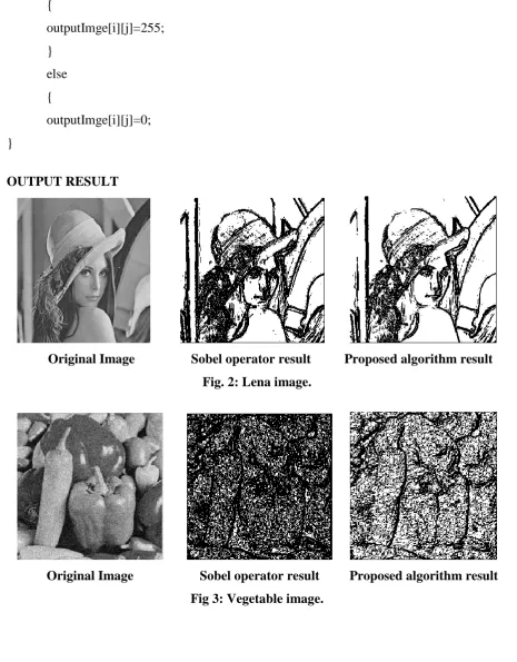
OUTPUT RESULT
Original Image Sobel operator result Proposed algorithm result Fig. 2: Lena image.
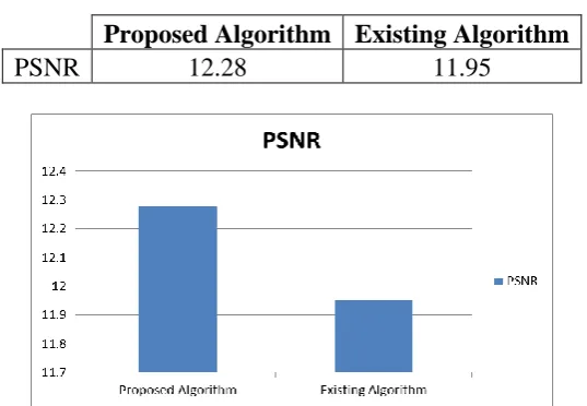
Table 5.1: PSNR values of Proposed Algorithm and Existing Algorithm Proposed Algorithm Existing Algorithm
PSNR 12.28 11.95
Fig. 5.2: PSNR values of Proposed Algorithm and Existing Algorithm. Table 5.2: MSE values of Proposed Algorithm and Existing Algorithm
Proposed Algorithm Existing Algorithm
MSE 3843.14 4149.83
Fig. 5.3: MSE values of Proposed Algorithm and Existing Algorithm. Table 5.3: MAE values of Proposed Algorithm and Existing Algorithm.
Proposed Algorithm Existing Algorithm
MAE 35.37 37.67
CONCLUSION AND FUTURE SCOPE Conclusion
It is clear from the obtained results that the existing technique gives noisy output. But the
purposed modified sobel operator edge detection gives better results as shown in fig 5.1(a).
The results can further be improved by changing threshold value. By increasing threshold
value noise is reduced but some thin edges are also lost as shown in fig 5.1 (b). Thus by using
an appropriate threshold value, edge detail as per a given requirement can be obtained.
Future Scope
The purposed algorithm can produce better results by further modification in the algorithm.
The proposed technique is restricted only to gray scale images, this can be extended to color
images in that case, and the detection would become significantly more complex.
REFERENCES
1. Feng-ying Cui and Li-jun Zou, Bei Song, “Edge Feature Extraction Based on Digital
Image Processing Techniques”, Proceedings of the IEEE International Conference on
Automation and Logistics Qingdao, China, September 2008.
2. Sivakamasundari. J, Kavitha. G, Natarajan. V and Ramakrishnan. S, “Proposal of a
Content Based Retinal Image Retrieval System Using Kirsch Template Based Edge
Detection”, 3rd International conference on informatics, electronics & vision, 2014.
3. Sheng Yi, Demetrio Labate, Glenn R. Easley∗, and Hamid Krim, “Edge detection and
processing using shearlets”, IEEE, 2008; 1148-1151.
4. Mrityunjay Kumar Ray, Deboleena Mitra, “Simplified Novel Method for Edge Detection
in Digital Images”, Proceedings of 2011 International Conference on Signal Processing,
Communication, Computing and Networking Technologies (ICSCCN 2011).
5. Bin Pan Junfeng Wu Zhiguo Jiang Xiaoyan Luo, “Shadow detection in remote sensing
images based on weighted edge gradient ratio”, IEEE, 2014; 505-508.
6. Wei Wang, Huaping Xu, “Edge Detection of SAR Images Based on Edge Localization
with Optical Images”, IEEE Trans. On Pattern Analysis and Machine Intelligence, pami,
Nov. 2014; 8(6): 679-698.
7. Anitha, S.Malarkkan, J.Premalatha, V.Manonmani, “Comparison of Standard Edge
Detection Techniques Along with Morphological Processing and Pseudo Coloring in
8. Girish Chap Ie, R. D. Daruwala, Member, IEEE, “Design of Sobel Operator based Image
Edge Detection Algorithm on FPGA”, International Conference on Communication and
Signal Processing, April 3-5, 2014, India.
9. Anna Fabijańska, Dominik Sankowski, “Edge Detection in Brain Images”, MEMSTECH,