Design Of 2 X 2 Mimo-Dra Antenna For 5g
Communication
Dr.M.Kavitha, Dr.S.Shanthi, A. Beno, B.Arul Rajan, Dr.M.Sathish
Abstract: MIMO antenna with higher bandwidth and high-speed connectivity becomes the ideal solution for the future 5G wireless applications. The proposed structure has 2 x 2 MIMO DRA configuration with dimension of 20 mm x 20 mm with the thickness of 1.6 mm and feed used is slot coupled microstrip feed. The entire structure is fabricated on a FR4 structure and two dielectric resonators made up of Roger 5880 is placed on top of the slot which is act as feed. The structure is simulated using CST studio. The proposed 2 x 2 MIMO DRA antenna operating at 28 GHz from 26.7 GHz to 29.5 GHz have very low correlation coefficient less than 0.005 and reasonable gain above 9.99 dBi with stable pattern diversity which validates that our proposed structure is the right candidate for the next generation wireless 5G communication.
Index Terms: MIMO, two port antenna, 5G antenna, DRA, decouple.
—————————— ——————————
1.
INTRODUCTION
One of the smart antenna techniques [1] is Multiple Input Multiple Output (MIMO) Antenna Technology. The MIMO technology has gained more attention in the recent past because it can transmit more data with the help of multiple antennas. The MIMO technique consists of multiple numbers of antennas at the transmitter as well as the receiver side. MIMO make use of multipath phenomenon, where the data is received in the receiver multiple times with some time delay [2]. The performance of the MIMO is measured using envelope cross correlation (ECC) between the different antenna. The aim of MIMO is to maximize the capacity by reducing the ECC. The next generation mobile technologies will solely rely on the 5G standards in order to meet the ever-increasing demand of higher data rate, which can be achieved with the help of larger bandwidth. And therefore, the mm and sub-mm wave bans has attracted the researchers more. Several kinds of antenna such as micro strip and array are widely used in milli-meter wave band, but the major disadvantage is the surface wave loss and metallic losses. it is necessary [3]overcome these barriers,[8] the dielectric resonators are used, which has many advantages such as no surface wave loss and high efficiency at mm-wave spectrum . This work [4] electric resonator antenna consists of the dielectric structure with relative dielectric constant varies from 3 to 100, that is excited with the help of coupling feed line. There are many geometries and their design procedures [5] available in the literature.
The met material [7] and dielectric resonators are integrated with antenna in order to achieve bandwidth, gain and multiband. It is used for [6]control both the quality factor and the resonant frequency. The dielectric resonator with high permittivity is used because it can restrict the quality factor. High quality factor will reduce the bandwidth, which is the key issue that needs to be addressed in the design of DRA[9-11]. But the use of DRA -MIMO antenna is not widely investigated for the 5G communication platform. Since the MIMO can able to overcome the multipath effects, the DRA-MIMO combination will result in novel antennas that can be used in 5G communication.The design procedure of the proposed two elements MIMO-DRA is explained in section II. The simulated results are explained in section III in order to validate the proposed MIMO-DRA for 5G communication and conclusion is arrived in section IV.
2.
TWO
ELEMENT
MIMO-DRA
DESIGN
PROCEDURE
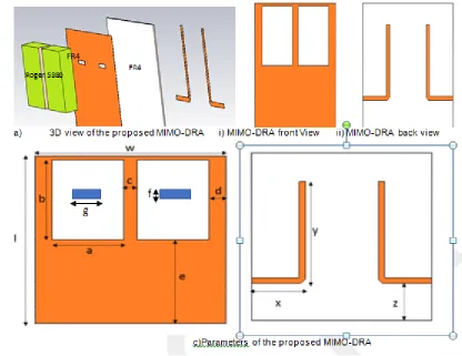
The geometry and its parameter values of the proposed MIMO-DRA for 5G communication is depicted in figure 1 and Table I respectively. The proposed antenna is a four-layer structure, a FR4 structure is chooses for the fabrication with feed line on one side and ground with two slots is printed on the other side forming a three layer structure. The two dielectric resonators (DR) is placed on top of the slots forming the fourth layer. Two dielectric resonators are placed on top of the square ground plane of size 20 mm x 20 mm. The DR’s are made up of the roger 5880 material with relative permittivity of 9.8 with the dimension of 7.5 mm x 9.5 mm x 0.8 mm. The Two DR’s are excited with help of slot in the ground plane which is fed with microstrip feed which is printed on the FR4 substrate. In figure 1 the 3D view, front and back view of the proposed MIMO-DRA is clearly depicted. We can observe from figure 1, that the entire structure is printed on a FR4 substrate. ______________________________
Dr.M.Kavitha, Professor, Department of ECE, K.Ramakrishnan College of Technology, Trichy, Tamilnadu India.
Dr.S.Shanthi ,Professor, Department of ECE, Saveetha School of Engineering, Chennai
Dr.A.Beno, Associate Professor, Department of ECE,
Dr.Sivanthi Aditanar College of Engineering, Tiruchendur, Tamilnadu India. B. Arul Rajan, Assistant Professor, Department of ECE, St. Mother Theresa Engineering College, Tamilnadu, India.
Figure 1 Geometry of the proposed antenna
Table I Dimension of the Proposed MIMO-DRA
l w a b c d e
20 20 7.5 9.5 1.4 1.8 10
f g x y z h t
0.5 2.2 5.62 12.3 4 1.6 0.0035
In figure 2 the simulated S parameter of the proposed MIMO -DRA is depicted, which shows the S11 is reasonably below -10dB in the resonating band of 28 GHz from 26.7
GHz to 29.5 GHz which is the FCC standard spectrum for 5G communication.
Figure 2 S-parameter of the proposed MIMO-DRA
3.
RESULT
AND
DISCUSSION
Figure 3 and Figure 4 clearly depicts the reflection and transmission coefficient plot, it is observed that at 28GHz resonant frequency the return loss is -37 dB and the isolation is above -15 dB. The proposed MIMO DRA structure is having a decent value in both the return loss
and isolation and hence it is used for the 5G communication.
FR4 Roger 5880
s-pa
ra
me
te
Figure 3 Reflection Coefficient of the proposed MIMO-DRA
Figure 4 Transmission Coefficient of the proposed MIMO-DRA
Figure 5 Surface Current of the proposed MIMO-DRA
In Figure 5 the surface current of the proposed MIMO-DRA is presented when the a) port 1 is excited and b) port 2excited respectively. From the Figure 5, it is observed that the surface current is evenly spread over the entire
structure and there is very less mutual coupling without any external isolation improvement technique. Similarly, in figure 6 the 3D gain pattern when port 1 and 2 excited is presented, from which we can observe that maximum gain
in turn directivity is achieved perpendicular to the DRA axis.
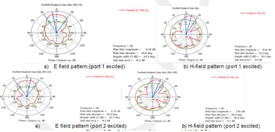
Figure 6 Far field pattern of the proposed MIMO-DRA
Re
fl
ec
ti
on
coe
ff
ic
ie
nt
Tra
ns
mi
ss
ion
coe
ff
ic
ie
In figure 6, the E field and H field pattern when port 1 and port 2 is excited is presented. The radiation pattern of the proposed MIMO DRA is showing a stable pattern in the entire resonating band. The E plane and H plane has an unidirectional pattern which is the major requirement for any communication application. The antenna MIMO performance is decided with the help of antenna diversity parameter. There are three types of diversity realization techniques 1) spatial diversity, 2) polarization diversity and 3) pattern diversity. This work makes use of spatial diversity technique to realize the antenna diversity and to improve the isolation between two closely coupled antennas. The ECC is used to measure the isolation between two closely couple antennas, which can be measure either with the help of far field pattern or S parameter. When the value of ECC is lower, then the MIMO antenna diversity
performance is good. The formulae to find out the Envelope correlation coefficient between antennas i and j in an N-element MIMO antenna system is
𝜌 (𝑖, 𝑗, 𝑁) = | ∑ , ,
|∏ , ( ∑ , , )|| (1)
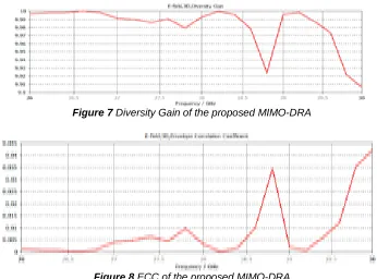
Figure 7 shows the diversity gain performance of the proposed MIMO DRA antenna for 5G communication. The diversity gain is more than 9.99 dBi. In figure 8 the simulated ECC using CST software based on S parameter is presented. The ECC value is less than 0.005 in the resonating band, which clearly reveals that the proposed MIMO-DRA antenna for the 5G communication application is having a good antenna diversity performance.
Figure 7 Diversity Gain of the proposed MIMO-DRA
Figure 8 ECC of the proposed MIMO-DRA
4.
CONCLUSION
A 2 x 2 MIMO DRA antenna is designed for 5G communication application. Two dielectric resonators are place on top of the slot in the ground. A novel microstrip feed slot is used as feed for the dielectric resonators. The dielectric resonator is made up of high permittivity dielectric material Roger 5880. The entire structure is resonating at 28 GHz band from 26.7 GHz to 29.5 GHz with a maximum return loss value of -37 dB. It is also observed that good isolation performance is shown by proposed MIMO-DRA structure. The Diversity gain of the proposed structure is maintained above 8.5 dBi in the entire operating frequency and its envelope correlation coefficient is less than 0.005. The surface current of designed antenna clearly shows that the structure is having very less coupling fields and a stable radiation pattern. The proposed MIMO DRA is the best choice for the 5G communication because of its small size and good performance.
REFERENCES
[1]. J.Kornprobst, K. Wang, G. Hamberger and T. F. Eibert, (2017) "A mm-Wave Patch Antenna with Broad Bandwidth and a Wide Angular Range," in IEEE Transactions on Antennas and Propagation, vol. 65, no. 8, pp. 4293-4298. [2]. A Ali Nazar, R Jayabharath, MD Udayakumar
[2014] ―An ANFIS Based Advanced MPPT Control of a Wind-Solar Hybrid Power Generation System,‖ international review of modelling and simulations. vol.7, no. 4, pp. 638– 643.
[3]. S. Prasad Jones Christydass, N. Gunavathi.(2017) "Co directional CSRR inspired printed antenna for locomotive short range radar‖, International Conference on Inventive Computing and Informatics (ICICI).
[4]. A Nazar Ali, D Sivamani, R Jaiganesh M Pradeep [2019], ―Solar powered air conditioner using BLDC motor,‖ IOP Conference Series: Materials Science and Engineering, vol. 23.
Diversity
Gain
[5]. S. Prasad Jones Christians, N. Gunavathi.(2017) "Design of CSRR loaded multiband slotted rectangular patch antenna", IEEE Applied Electromagnetics Conference (AEMC).
[6]. V Venkatesh, A Nazar Ali,, R Jaiganesh. V indiragandhi [2019], ―Extraction and conversion of exhaust heat from automobile engine in to electrical energy Energy‖, IOP Conference Series: Materials Science and Engineering, vol. 23.
[7]. A. Nazar Ali, R. Sagayaraj and R.Jaiganesh. "Analysis the performance of Embedded ZSI fed Induction motor under semiconductor failure condition‖.TAGA JOURNAL VOL 14(2018): 1634-1644.
[8]. Prasad Jones Christydass and Pranit Jeba Samuel, "Metamaterial Inspired Slotted Rectangular Patch Antenna for Multiband Operation ", Biosc. Biotech. Res. Comm, Special Issue, Vol 12, No (6), pp 57-62,Nov 2019.
[9]. Subramanian, AT Sankara, P. Sabarish, and R. Jai Ganesh.[2017] "An Improved Voltage follower Canonical Switching Cell Converter with PFC for VSI Fed BLDC Motor." Journal of Science and Technology (JST)2.10 01-11.
[10]. Sabarish, P., Sankara Subramanian, A.T., Gayathri, A., Anton Amala Praveen, A. C.[2019] ―A Novel wearable therapeutic aid with intelligent information processing systems‖ IOP conference series: Materials science and engineering . [11]. Shyam D, Premkumar K, Thamizhselvan T,
Nazar Ali A, Vishnu Priya M ―Symmetrically Modified Laddered H-Bridge Multilevel Inverter with Reduced Configurationally Parameters ―International journal of engineering and advanced technology‖Vol 9, issue 1, Oct 2019 [12]. K. M. Luk and K. W. Leung,(2003) Dielectric
Resonator Antennas, Research Studies Press. [13]. A.Nazar ali, Dr.R.Jayabharath, R.Shanthi
Priyadharshini. ―A Single phase high efficient transformer less inverter for PV Grid connected power system using ISPWM technique." International Journal of Applied Engineering Research (IJAER) Volume 10, No.9 (2015), pp.7489-7496
[14]. A.Nazar Ali and R. Jayabharath. "Performance Enhancement of Hybrid Wind/Photo Voltaic System Using Z Source Inverter with Cuk-sepic Fused Converter." Research Journal of Applied Sciences, Engineering and Technology7.19 (2014): 3964-3970.
[15]. K. Premkumar and B.V. Manikandan, ―Stability and Performance Analysis of ANFIS Tuned PID Based Speed Controller for Brushless DC Motor,‖ in CURR SIGNAL TRANSD T, vol.13, no.1, 2018, pp. 19-30. [16]. Premkumar et al. (2015), GA-PSO optimized online
ANFIS based speed controller for Brushless DC motor, Journal of Intelligent & Fuzzy Systems, 28, 6, pages.2839-2850.
[17]. K Premkumar et al. (2018), Novel bacterial foraging-based ANFIS for speed control of matrix converter-fed industrial BLDC motors operated under low speed
and high torque, Neural Computing and Applications, 29, 12, pages.1411–1434.