INTRODUCTION
Ceramic foam is currently a very exciting area of research due to its wide applicability. Many of the authors have conducted extensive reviews
on the subject. Buciuman1 mentioned that ceramic
foams have been in development for around three decades, and are now used commercially as filters for molten metal and hot gases. In recent years,
www.orientjchem.org
CODEN: OJCHEG 2011, Vol. 27, No. (4): Pg. 1293-1301 Est. 1984
An International Open Free Access, Peer Reviewed Research Journal
Ceramic Foam Synthesis and
Its Modification for Use at High Temperature
KAREN PEÑA¹, VANESSA S. GARCIA-CUELLO¹,
LILIANA GIRALDO¹ and JUAN CARLOS MORENO-PIRAJAN²*
¹Department of Chemistry, Faculty of Sciences, Universidad Nacional de Colombia, Ciudad Universitaria, Carrera 30 No. 45 03, edificio 451, Bogotá-Colombia.
²Research Group on Porous Solid and Calorimetry, Department of Chemistry, Faculty of Sciences, Universidad de Los Andes, Carrera 1 No. 18 A 10, Bogotá, Colombia
*Corresponding author: Tel.: +57 1 3394949 2786. E-mail address: [email protected]
(Received: September 20, 2011; Accepted: November 19, 2011)
ABSTRACT
Many properties of open-cell ceramic foam prepared by means of the sponge replication method can be controlled by adjusting the viscosity of the ceramic slip with respect to the pore count of the polymer sponge template. Ceramic foam obtained by this method was subsequently coated with various materials, such as urea-formaldehyde and carboxymethylcellulose (CMC), and its structural properties were analysed and interpreted in order to establish its potential applicability as a thermal insulator. Ceramic foams were prepared with different densities by varying the density of the ceramic slurries used (1.1845, 1.2798, 1.3567, 1.54332, 1,6543 and 1,7234 g/cm3). The physical properties of the ceramic foam produced, such as density, were characterised according to ASTM C 271-94, whereas porosity was characterised using the Archimedes method. The foams were analysed with XRD, SEM and FTIR, among other techniques.
Key words: Foam, Ceramic, Isolated temperature, Mullite.
the turbulence of the flow. Foam carriers exhibit a high contact surface between the gas phase and the solid, and can be manufactured in different geometries, allowing for adjustment of axial or radial flow patterns in the reactor. Pioneering work reported in the field of catalysis with foam carriers
concerned the partial oxidation of hydrocarbons1-4,
catalytic combustion5,6, and the removal of soot from
diesel exhaust1,7,8. There are several routes for
manufacturing ceramic foams. Among these, the polymer sponge replication method of
Schwarzwalder and Somers9 is most suitable for
the fabrication of oxidic, reticulated foams with easily
accessible, open cells10,11. This method consists of
coating an elastic polymer sponge with open cells with a slip containing the precursors of the ceramic material together with other additives. Coating is achieved by immersing the polymer sponge into the slip, expelling the excess (e.g. by compression), and drying. Subsequently, the green body is exposed to a temperature treatment. In a first stage, the organic skeleton is burned off in air. At temperatures above 1400°C, the particles forming the ceramic replica are sintered.
There are several developments that have been published in the area of the synthesis of ceramic foam and the various uses they may have. Have published a number of routes for ceramic foams according to the final application is required to give. In this work, we have based on already
published work1, we want to enhance the process
of ceramic foam synthesis and the study of density, but mainly we wish to explore the use of simple treatments with molecules for establishing whether organic chemical compounds can improve their thermal isolation properties.
EXPERIMENTAL Foams synthesis
In our research, the procedure used for the synthesis of ceramic foam is based on the
publication of Buciuman1. The ceramic foam carriers
were made by means of the polymer foam replication
method9. Polymer sponges were used (polyester,
Koepp AG), with a pore size of the range of 50 ppi,
and cut into pieces of 30-60 mm diameter. Most of the work reported here was carried out with alumina-mullite foams. For the preparation of the respective slip, the ceramic precursors (boehmite, kaolin and silica in a weight ratio of 4.5:3.5:2) were suspended in water containing poly(vinylpyrrolidone) (Luviskol, BASF™) as an organic binder and Dolapix PC 67
(Zschimmer & Schwarz®) as a deflocculant. The
mixtures were milled with alumina balls for 45 min. The slip was used to coat polymer sponges of different pore counts with 50 ppi. The various combinations used for the production of the other foam ceramics are summarised in Table 1. The solid content (based on the mixtures) was varied to produce ceramic slurries with densities of 1.1845,
1.2798, 1.3567, 1.54332, 1.6543 and 1.7234 g/cm3,
in a distilled water medium12. Coating was performed
by immersing the sponge pieces in the slurry, squeezing them, and passing them through rollers preset at 80% impression to expel the excess slip. The bodies were dried for 24 h at room temperature and heated at 1°C/min to 700°C, and then a further at 10°C/min to the final temperature (1800°C), which was held for 500 min to achieve sintering of the ceramic.
Characterization of foams synthesized
The proper ties of the ceramic foam produced were characterised according to ASTM C 271-94 and the porosity was characterised using the Archimedes method. The morphological study was perfor med using a scanning electron microscope (JEOL). Different analysis techniques were used to characterise the synthesised ceramic samples: with CuKá radiation. Powder diffraction
data were collected in the 2θ ranges 4–80° in steps
of 0.02° 2θ, with 1s per step. The operating voltage
and current were 40 kV and 45 mA. Photographs of samples were taken with a digital camera (Casio™, Japan). Scanning Electron Microscopy micrographs were obtained with a Hitachi S-2400 instrument. Nitrogen adsorption isotherms were measured at
liquid N2 temperature (-196 °C) and N2 pressures
ranging from 10-6 to 1.0 p/p
o with a Autosorb 3B
(Quantachrome, Boynton beach, USA)13,14. The
T
a
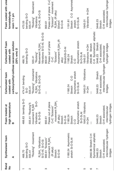
ble 1:
Vibrations and bending of infrared spectra of ceramic f
oams
Band
Synthesised
foam
Foam treated at
Carbonated
foam
Carbonated
Foam
Foam coated with
urea-No high temperature coated with coated with formaldeh yde A B carbo xymeth yl-celllose sacar ose solution
resin 1:1 p/v
C
(20% w/w) D
E
1
466.70
466.63 bending Si-O
474.41 bending 466.70 470.55 bending Si-O Si-O bending Si-O bending Si-O 2 555.41 555.41 “Roc king”5 555.41 555.41 “Roc king” mo v ement mo v ement R2 SiH “Roc king” mo v ement 555.41 “Roc king” Mo v ement Vibr
ations
R 2 SiH 2 Vibr ations “Roc king” Vibrations R 2 SiH 2 Vibr ations Al, Si-O-Si Si-O-Al, Si-O-Si M o v ement R2 SiH 2 Si-O-Al, Si-O-Si Si-O-Al, Si-O-Si V
ibrations Si-O-Al, Si-O-Si
3 900.61 “Scissors” 900.61 — 900.61 900.61 mo v ement R 2 SiH 2 Fle x
es out of plane
Fle
x
es out of plane
Fle x es out of plane C=C (R alkyl) C=C “Scissors” C=C “Scissors” mo v ement Stretch m o v ement R 2 SiH 2 “Scissors” R 2 SiH 2 (R alky) Si-O-Al (R alky) mo v ement R2 SiH 2 (R Stretch Stretch alky) Si-O-Al Si-O-Al StretchSi-O-Al 4
1180.24 Asymmetr
ic 1180.24 1180.24 1180.24 1191.81 stretch Si-O-Si,Al Stretch Stretch C-O Stretch S tr e tc h C -O A s y m m e tr ic C -O Asymmetr ic stretch C -O stretch Asymmetr ic stretch Si-O-Si,Al Asymmetr ic stretch Si-O-Si,Al Si-O-Si,Al Si-O-Si,Al 5 -1645.01 V ib rations 1645.01 V ib rations 1645.01 1645.01 H-OH H -O H V ib rations H-OH
Vibrations H-OH
6 2940.96 Stretch C-H — —
2940.96 Stretch
-Symmetr
ical
aliphatic
C-H Symmetr
ical aliphatic
7
3446.23
3446.23
3446.23 Stretch
T
a
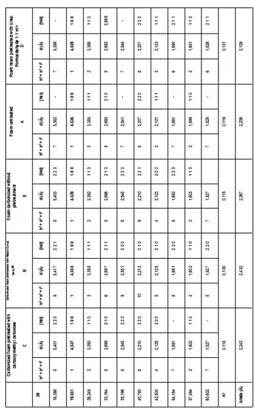
ble 2:
DRX lines of ceramic f
oam synthesize
RESULTS AND DISCUSSION
Figs. 1(a) and (b) show a variation of porosity which is determined using the Archimedes method, and density which is determined according to ASTM C271-94 of the ceramic foam produced as a function of the slurry density. From Fig. 1(a), it is clear that the porosity of the ceramic foam decreases as the slurry density increases, as
reported in the literature1. As the porosity decreases,
the density of the ceramic foam increases as shown in Fig. 1(b) and then decreases to a value of 1.543, then increases due possibly to increase the number of pores per unit volume. The quality of ceramic foam is strongly influenced by the density of the slurry, as this reflects the degree of porosity. Reducing the porosity will consequently increase the density of ceramic foam from 1.2798 to 1.54332
g/cm3. However, it was found that a slurry density
greater than 1.54332 g/cm3 is undesirable, as this
promotes the formation of cavities inside the ceramic foam which could be attributed to poor slurry flow and coating.
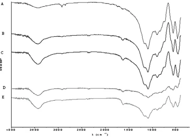
Infrared spectroscopy is one method frequently used to identify character istics groups (see Table 1 and Figure 2). In this case, this technique is used to character ise the materials as aluminosilicates foams, pretreated with different types of impregnation and then carbonized. In the spectra obtained, a broad
and intense band located between 1200 cm-1
and 800 cm-1 can be seen, which generally
represents the asymmetrical stress vibration of Si-O-Si and Al. The band located at around 1645
c m- 1 fo r e a c h s y s t e m c o r r e s p o n d s t o t h e
deformation vibration of the H-OH bond, as the high content of the impregnation solution poly(vinylpyrrolidone) that penetrates the pores p r eve n t i n g t h e eva p o r a t i o n o f wa t e r. T h e i n c r e a s e d i n t e n s i t y o f t h e b a n d m ay b e associated with a greater number of water molecules in the material, so this band is not obser ved in untreated foam. This is fur ther evidenced by the OH groups associated with the water retained by the material, as indicated
by the absorption bands near 3500 cm-1 which
exhibit minimum strength. The bands in the
region between 600 cm-1 and 900 cm-1 are
related to stretching vibrations of the Al-O bond,
specifically to Al ions with coordination number 4. Those located in the region between 400
c m-1and 600 cm-1 may be associated with
deformation vibrations of Si-O-Si and Si-O-Al. It is reported that the intensity of this band may be associated with a higher crystallinity of the material, which would indicate that an increase
in the SiO2/Al2O3 ratio causes an increase in
the presence of cr ystalline systems in the material, which is expected to negatively affect the mechanical performance.
The persistence of bands in the region
between 1200-800 cm-1 and 470 cm-l, corresponding
to the vibrations of Si-O-Si, Al and Si-O, seem to indicate that these are be aluminosilicate foams, a
three-dimensional structure of tetrahedral [SiO4I
4-compact with a predisposition to high porosity. The
absorption band of Si-O can occur at 900 cm-1 to
1200 cm-1. In this step, a decrease in the disturbance
generated in the silica lattice would show the presence of the tetra-coordinated aluminium atoms listed there, as mentioned previously. The measurements show that the use of urea-formaldehyde resin and carboxymethyl cellulose makes this band diminish or disappear, probably because it starts to show the beginning of a different organisation, but not daring to predict whether this rearrangement is more or less sensitive to the use of resin.
Fig. 1: (a) Porosity and (b) bulk density of ceramic foam as a function of increasing slurry density
Fig. 3: DRX of ceramic foam synthesised
Fig. 4: Images of ceramic foams: a) Ceramic synthesised by normal procedure, b) Ceramic foam under high thermal treatment
(a) (b)
species in the interlayer space of the aluminosilicate material as a result of the impregnation action.
This result is confirmed by the reduction in basal spacing, after impregnation, resulting in a more stable species and a larger cell volume.
Figure 4 show a photograph of the ceramic foam produced in this research. Figure 4a show the foam synthesized according to the procedure proposed initially, and Figure 4b shows the sample treated at a high temperature to analyse its stability with respect to this variable. It can be seen that its lattice is virtually the same, which is observable
without thermal treatment, so the foam can be used as an isolated thermic layer, for example.
Fig.5: Scanning electron microscope of ceramic foams. a) Ceramic foam by normal procedure b) Ceramic foam with coated CMC. c) Ceramic foam with coated urea-formaldehyde resin
(c)
(b) (a)
here is very interesting as the porosity is completely closed. This is important because in the resistance and temperature isolation tests this ceramic realized the best results. Finally, the ceramic foam treated with urea-formaldehyde (see Figure 5c) also shows blocked pores, although with minor resistance to temperature. On the other hand, the nitrogen adsorption isotherms did not develop on the surface area (not shown) whose highest value was achieved on the initial ceramic foam with a value of
7 m2/g, whilst the CMC-coated ceramic foam
presented an area of up to 2 m2/g, which we believe
contributed to the high performance of the synthesized foams regarding their insulation against temperature.
When testing the ability of insulation for temperature results showed that ceramic foam coated with CMC and phenol-formaldehyde resin, shower of major capacity, registering temperatures up to 1200 ÚC so that the temperature in the external environment was greater than 40 ÚC. These tests are not described in this work and that will be the subject of another publication which is fully explained as the experiments conducted and results achieved
CONCLUSIONS
ceramic foam are greatly influenced by the density of the ceramic slurry. An increase in the density of the ceramic slurry enhances the strength of the foam as well as its density, thus making the foam denser. Coating with CMC and urea-formaldehyde resin showed an improvement in the properties of ceramic foam, turning it into a material with excellent insulation properties. This result is explained by the fact that these materials cause a closure of the pores, shown by the measurements of nitrogen adsorption isotherms. Temperatures of up to 1200ÚC were
registered without that the structure of foams significantly affect
ACKNOWLEDGMENTS
The authors wish to thank the Master Agreement established between the University of Andes and the University National of Colombia, and the Memorandum of Understanding entered into by the Departments of Chemistry of both universities.
1. Buciuman F.C., Kraushaar-Czarnetzki B., Ind.
Eng. Chem. Res. 42: 1863 (2003).
2. Flick D.W., Huff M.C., Appl. Catal. A: Gen.,
187: 13 (1999).
3. Twigg M.V., Richardson J.T., Preparation and
properties of ceramic foam catalyst supports. In: Studies in Surface Science and Catalysis: Preparation of Catalysts VI, G.Poncelet, J. Martens, B. Delmon, P.A. Jacobs, P. Grange, (eds.) Elsevier: Amsterdam, 91: 345 (1995).
4. Cerri I, Saracco G, Specchia V., Catal. Today,
60: 21 (2000).
5. Antsiferov V.N., Kalashnikova M.Y., Makarov
A.M. Filimonova I.V., Russ. J. Appl. Chem. 70(1): 105 (1997).
6. Saracco G, Badini G, Specchia V., Chem.
Eng. Sci. 54: 3035 (1999).
7. Van Setten B.A., Bremmer J, Selles S.J.,
Makkee M, Moulijn J.A., Catal. Today 53: 613
(1999).
8. Ciambelli P, Palma V, Russo P, Vaccaro S.,
Combust. Sci. Technol. 153: 325 (2000).
9. Schwarzwalder K, Somers A.V., Method of
making porous ceramic articles. U.S. Patent 3 090 094, 1963.
10. Saggio-Woyanski, C.E. Scott Minnear W.P.,
Am. Ceram. Soc. Bull. 71: 1674 (1992).
11. L.M. Shepard, Porous ceramics: Processing
and applications. In: Ceramic Transactions: Porous Materials, K. Ishizaki, L. Sheppard, S. Okada, T. Hamasaki, B. Huybrechts, (eds.) American Ceramic Society: Westerville, OH, 31: p. 3 (1993).
12. Muhamad M.A.A., Hongb L.C., Ahmad Z.A.
Aki H.M., Journal of materials processing
technology, 207: 235 (2008).
13. Garcia-Cuello V.S., Giraldo L, Moreno-Piraján