Effect Of Radial And Axial Clearance On The
Performance Of A Specially Designed Savonius
Vertical Axis Wind Turbine
EL-Samanoudy, M. A.
, Ghorab A. A. E., Ibrahim. W. Fawy
Prof DR., Mechanical Power Engineering Department, Faculty of Engineering, Ain Shams University, Cairo, Egypt
Prof DR., Mechanical Power Engineering Department, Faculty of Engineering, Ain Shams University, Cairo, Egypt
Mechanical Power Engineering Department, Faculty of Engineering, Ain Shams University, Cairo, Egypt
Abstract: Savonius Wind Turbine (SWT) has a simple construction and can produce electricity in any wind direction. Although Savonius wind rotor has many advantages, but it has a low power coefficient when compared with other horizontal and vertical axis wind rotors. In this paper; an experimental study is carried out to investigate the effect of geometrical parameters (radial and axial clearances) on the performance of SWT in terms of torque coefficient and power coefficient. For this reason, analysis is carried out to optimize and improve the operation of such turbines. Two buckets' Savonius rotor model was selected, designed and manufactured with a diameter of 80 cm and height of 80 cm; without having a shaft between the end plates. The designed model was fabricated and tested in a low speed wind tunnel under an open type test section.The results of the present study shows that, a maximum power coefficient (Cp) of 0.076 was obtained at a clearance (ea) = 0.14d in axial direction. The specially designed Savonius wind turbine with clearance (er) = 0.09d and (er) =0.115d in radial axis arehavingthe highest coefficient of torque than the one in the conventional Savonius rotor.
Keywords: Specially designed Savonius rotor, Radial clearance, axial clearance, Coefficient of Power.
1.
Introduction
Wind energy is a clean source of energy without producing pollution and greenhouse gases. Wind power is used to generate electricity by using wind turbines that transform the kinetic energy of the wind into mechanical energy and then into electricity. In order to find new solutions to improve the aerodynamic efficiency of Savonius turbine, Roy and Saha [1]; studied two bladed Savonius rotor with change in the blade arc geometry and comparing the performance of the new modification with standard blades like semi-elliptic, semi-circular and modified Bach type. Tests through open type and a low speed wind tunnel on new modified blade and standard blades were conducted. It was observed that; change in arc geometry overcomes the effects of negative torque and the magnitude of the static torque coefficient increases. The results show also that the maximum coefficient of static torque increases by 31% in new modification and the power coefficient increases up to Re=1.2 x10⁵ beyond which it again improve the aerodynamic performance of the Savonius wind rotor. A Four models of Savonius turbines were designed and Vertical Axis Wind Turbines (VAWTs) are more preferred in small-scale power generations because they can produce electricity in any wind direction and electrical equipment can be placed at a ground level. Savonius turbine is considered to be of S-Shaped cross section with 2 semi-cylindrical shaped rotor that consists of 2 or 3 blades and considered as a drag device.The aerodynamic efficiency of Savonius wind turbine is lower compared with the other types of wind turbines. In order to improve the aerodynamic efficiency of the turbine, several studies have been performed in recent years by researcher’s todecreases. Kamoji et al. [2] experimentally studied the effect of blade
jet wind tunnel. The results show the modified Savonius turbine without shaft gives the Cp of 0.21 at Re of 1,50,000 whereas the modified Savonius rotor with shaft gives a Cp of 0.143. His conventional Savonius gives a Cp of 0.175. For the modified and conventional Savonius turbines, the maximum coefficient of static torque was found at a rotor angle of 30° and a minimum coefficient of static torque at a rotor angle of 165°. N.H. Mahmoud et al. [7] studied the geometrical parameters of two models of Savonius turbines with 2, 3 and 4 blades in the open jet wind tunnel at various wind speeds. It was observed that the Savonious turbine with 2 blades has a higher power coefficient than the 3 and 4 blade wind turbine. The two stage rotor gives higher performance than the single stage rotor. In addition, the geometrical parameters like end plates, overlap ratios and aspect ratio increase the power coefficient. Keum Soo Jeon et al. [8] studied four models to determine the performance of the helical Savonius blade at helical profile twist angles 180° and two semicircular blades. The models were tested in an open type wind tunnel at different wind velocities V=6m/sec, to V=12m/sec. The present research work is concerned with the study of the radial as well as the axial clearances in conjunction with the operation of the vertical axis wind turbine aiming at improving its performance.
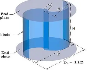
Figure 1: Experimental rig with Savonius rotor model
2. Experimental set-up
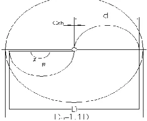
A wind tunnel is used having a square cross sectional area of 100cm x 100cm driven by double suction blower of 40 HP. The wind tunnel (Fig.1) was used to provide a constant wind speed of 5.8 m/s to test a specially designed Savonius wind turbine. Experiments were carried out to study the performance of a specially designed Savonius vertical axis wind turbine. The tested model has dimension (D = 800 mm diameter and H = 800 mm height) with an aspect ratio (As =H/D =1) as shown fig.(2).It consists of 2 semi-cylindrical shaped blade which has diameter of 400mm for each. The blades were fabricated from Aluminum sheets of thickness 0.7 mm mounted with end plates of diameter (Do = 810 mm) made of Artilon sheets. A Stainless steel shaft (tube pipe), with diameter 16mm is housing the upper and lower end plates. Two angular contact ball bearings (FAG) are mounted to the mild steel plate in order to support the Savonius rotor. The rotor was studied without central shaft between the end plates and with different clearance (overlap) between the 2 blades in radial and axial axis. A rope wrapped around a pulley installed on the lower shaft is connected with spring balance that has an accuracy of ±2%. It was used to measure the torque from no load to maximum load. A Tachometer device was used to measure the rotational speed at each load
applied to the turbine. While the wind speed is measured using a propeller-type digital anemometer that has accuracy of ±3%. Firstly, the turbine speed was measured without a load (maximum speed); then; a load was applied (as a tension force in a rope).
Figure 2: Geometrical parameters of Savonius rotor model.
The load was changed more than once and the break torque is calculated as the difference in tension in the string on both sides of the pulley. This difference is the braking torque. The braking torque was calculating by measuring the values of tension forces in both sides of the rope (T1&T2).
Calculations
Re = ρairVD /
T1 = T1 (kg) × 9.81, T2 = T2 (kg) × 9.81
= (T2 - T1) × r, ω = 2 Π N / 60 Apro. = H×D, Pact = τ × ω
Pav = ½ × ρair× V3× Apro., λ = (ω× r turbine) / V CP = Pact / Pav, CT = CP/λ
3. The Savonius rotor designed model
out to obtain the performance of the Savonius rotor in terms of the torque and power coefficients. In the present study the measurements were performed at a constant wind speed 5.8 m/sec and Reynolds number of 2.56 x 10⁵ (turbulent flow).
Figure 3: Blade model in radial axis with clearance(er).
Figure 4: Blade model in radial axis with clearance (e’r).
Figure 5: Blade model in axial axis with clearance (ea).
Figure 6: Blade model axial axis with clearance (e’a).
Figure 7: Investigated conventional Savonius rotor blade
with blade arc angle () = 180°.
4. Experimental Results
Experimental tests were carried out in a wind tunnel on twelve rotor model with different clearances in radial and axial directions and on the conventional Savonius rotor. The results were analyzed based on the effect of the clearance on the power and torque coefficients. These results were presented in the power coefficient (Cp) and the torque coefficient (CT) versus tip speed ratio () starting from no load to maximum load and then compared the performance with the conventional Savonius rotor. The conclusions of the results were discussed and presented as follows:
4.1 Results in radial direction
The experimental results of the rotor blade with radial clearance (er) and (e’r) are shown in figs.(8),(9),(10) and (11).
Figure 8: Coefficient of power Vs. Tip speed ratio for 2-
blades with radial clearance (er) and blade arc angle () = 180°.
Figure 9: Coefficient of torque Vs. Tip speed ratio for 2-
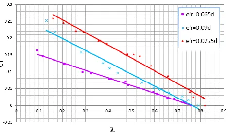
Figure 10: Coefficient of power Vs. Tip speed ratio for 2-
blades with (e’r) and blade arc angle () = 180°.
Figure 11: Coefficient of torque Vs. Tip speed ratio for 2-
blade with radial clearance (e’r)
Figures (8) and (9) Show that, Cp and CT values for rotor blade with a clearance equal to er = 0.09d, er = 0.115d and er=0.14d and blade arc angle 180. It was found that the maximum peak value of Cp at clearance (er) = 0.14d was 0.068 at = 0.44, and the maximum CT with value 0.27 at
=0.14 is obtained at the same clearance. Figures (10) and (11), show a comparison of Cp and CT characteristics for all rotor blade that designed with a clearance e’r =0.065d, e’r =0.0775d and e’r =0.09d in radial axis. It was found that the maximum peak of the Cp at a clearance (er) = 0.0775d was 0.064 at =0.44 and the maximum CT of 0.27 is obtained at
=0.16 is obtained at the same clearance.
4.2 Results in axial axis
Fig. (12) and (13) Show a comparison of Cp characteristics and CT depending on the Tip Speed Ratio () for all rotor blade designs with a clearance (ea) and (e’a) in axial axis.
Figure 12: Coefficient of power Vs. Tip speed ratio for 2-
blade with axial clearance (ea) and blade arc angle () =175° &174°and173° respectively
Figure 13: Coefficient of torque Vs. Tip speed ratio for 2-
blade with axial clearance (ea) and blade arc angle ()= 175&174°and173°respectively.
Figure 14: Coefficient of power Vs. Tip speed ratio for 2-
blade with (e’a) axial clearance and blade arc angle () = 175°&174°and173° respectively
Figure 15: Coefficient of torque Vs. Tip speed ratio for 2-
blade with (e’a) and blade arc angle ()=175°&174°and173° respectively.
and the maximum CT of 0.21 at =0.16 is obtained at a clearance (e’a) =0.09d and () =173°.
4.3 Results of Conventional Savonius
The performance of a conventional Savonius rotor (that has a half circle shaped of 180° blade arc angle, without shaft and with zero clearance) was experimentally tested under the same experimental conditions (at a constant wind speed 5.8 m/sec and Reynolds number of 2.56 x 10⁵. In order to make a comparison between the performance of the conventional Savonius rotor and the new specially designed with clearance in radial and axial axis. Figs. (16) and (17) illustrate the power coefficient and the torque coefficient for the conventional Savonius, The Cp.max is found as 0.066 at Tip speed ratio λ= 0.46 and the CT.max is 0.24 at Tip speed ratio λ= 0.12.
Figure 16: Coefficient of power Vs. Tip speed ratio for
Conventional Savonius 2-blade with blade arc angle () =180°.
Figure 17: Coefficient of torque Vs. Tip speed ratio for
Conventional Savonius 2-blade with blade arc angle () = 180°.
5. Comparison between performance of the new
specially designed rotor and the conventional
Savonius wind turbine:
Experimental comparison were carried out to study the performance of the conventional Savonius rotor and the new specially designed (with clearance in radial and axial axis). All results of this experiments are taken under identical experimental conditions. The maximum power and torque coefficient was obtained for rotor with clearance in axial axis.
Figure 18: Coefficient of power Vs. Tip speed ratio
Comparison for 2-blade at a clearance (er) in radial and axial axis with the Conventional Savonius rotor.
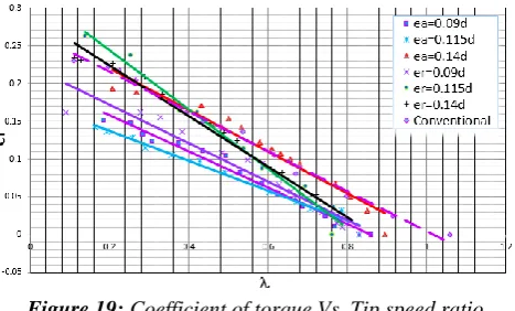
Figure 19: Coefficient of torque Vs. Tip speed ratio
Comparison for 2-blade at a clearance (ea) in radial and axial axis with the Conventional Savonius rotor.
Figure 20: Coefficient of power Vs. Tip speed ratio
comparison for 2-blade with a clearance (e’r) in radial and axial axis with the conventional Savonius rotor.
Figure 21: Coefficient of torque Vs. Tip speed ratio
Figs. (18), (19), (20) and (21) shows a comparison of the obtained results with the corresponding experiments. It showed that the maximum Cp is obtained at clearance (ea) = 0.14d in axial axis equal to 0.076 at tip speed ratio λ= 0.5 as shown in Figs (18). While the maximum CT equal of 0.26 at Tip speed ratio λ= 0.16. It has been obtained in radial axis at a clearance value equal (e’r= 0.115d) as shown in Fig. (21).it was found that the Savonius turbine with clearance in radial and axial axis gives better performance than that of the conventional Savonius turbine. The power coefficients value increase with the increase of tip speed ratio up to the maximum limit of power coefficient and then decrease with the increase in clearance value.
6. Comparison with previous investigators
Comparison of the present Savonius rotor with clearance (ea=0.14d) versus Zied Driss Savonius Rotor [9] at overlap (e-e’)/d=0.3 Figure (22) & (23).Figure 22: Zied Driss Savonius rotor [9] at overlap (e- e’)/d
= 0.3.
Figure23: Two-bladed Savonius rotor with clearance (ea) =
0.14d.
• Zied Driss Savonius Rotor at overlap (e-e’)/d=0.3 with dimensions (H=300 mm) height and diameter (d=100 mm) and tested at wind speed 8.8 m/s.
Figure 24: Comparison of present work and Zied Driss
Savonius rotor [9] at overlap (e-e’)/d = 0.3.
Figure 25: Comparison of present work and Zied Driss
Savonius rotor [9] at overlap (e-e’)/d = 0.3.
• This comparison shows that the power coefficient Zied Driss Savonius Rotor is higher than experimental Savonius wind turbine at Cp of 0.22 at (λ) 0.37.The range and the value of (λ) at peak Cp for the present rotor are greater than Zied Driss rotor due to the effect of lower Reynolds number (Re) value in the present study,as shown in fig.(24).
• The torque coefficient (CT) of the present Savonius rotor wind turbine is lower than Zied Driss Savonius Rotor [9] where (CT) 0.61 at (λ) 0.37 as showen in fig. (25). This is because of the difference in sizes, the Zied Driss Savonius rotor is smaller and lighter than the present Savonius rotor and works at higher wind speed than the present Savonius rotor.
7. Conclusion
1. The Savonius wind turbine with clearance ea=0.14d in axial axis gives the highest Cp of 0.076 at λ= 0.5 and the highest CT of 0.219 at λ=0.21.
2. The Savonius rotor with clearance (er) in radial axis has higher performance than the one in the axial axis at the same clearance value and blade arc angle.
3. The Savonius rotor with a clearance (e’r) in radial axis has lower performance than clearance in axial axis at same clearance value and blade arc angle.
4. The power coefficient increases up to a certain limit of clearance from (e’r) = 0.0775d to (e’r)=0.09d with blade arc angle () =174°and 173°
5. The specially designed Savonius wind turbine with a clearance (er) in radial and axial axis is having highest coefficient of torque than the one in the conventional Savonius rotor.
6. The Savonius rotor with clearance in axial axis gives a better performance as compared to the clearance in radial axis and conventional Savonius rotor.
Nomenclature
SWT: Savonius Wind Turbine VAWT: Vertical Axis Wind Turbine HAWT: Horizontal Axis Wind Turbine Cp: Power coefficient
CT: Torque coefficient
A: Projected area of the rotor (m2) D: Rotor diameter (mm)
Do: End plate diameter (mm) dsh : Shaft diameter (mm) H: Rotor height (mm)
N: Rotor rotational speed (rpm) Pav. Available power (W) Pact: Actual Power (W) τ: Torque (N.m)
T1: Tension force at fixed side (N) T2: Tension Force at adjustable side (N) V: Upstream air velocity (m/s)
ρ : Air density (kg/m3 )
ω: Angular velocity of rotor (rad ⁄ S) Re: Reynolds number
: Absolute viscosity of air (Pa s) λ: Tip speed ratio
: Blade arc angle (degree)
e: A clearance between the two blades (mm)
e’: A clearance between the blade and the intersection between the shaft and the other blade (mm)
ea: A clearance in axial axis (mm) er: A clearance in radial axis (mm)
REFERENCES
[1]. Sukanta Roy, Ujjwal K. Saha, 2015. “Wind tunnel experiments of a newly developed two-bladed Savonius -style wind turbine”, Energy Conversion and Management (ElSevier), 137: 117–125.
[2]. M.A. Kamoji, S.B. Kedare, S.V. Prabhu, 2008. “Experimental investigations on the effect of Overlap ratio and Blade edge conditions on the performance of conventional Savonius rotor,” Wind Engineering, 32:163-178.
[3]. Zied Driss, Ali Damak, Mohamed Salah Abid, 2015. “Evaluation of the Savonius Wind Rotor
Performance for Different External Overlap Ratios”. International Journal of Fluid Mechanics Thermal Sciences,1:14-19.
[4]. Arifin Sanusi, Sudjito Soeparman , Slamet Wahyudi Lilis Yuliati, 2016. “Experimental Study of Combined Blade Savonius Wind Turbine”. International Journal of Renewable Energy Research,6:614-619.
[5]. Mohammed Hadi Ali, 2013.“Experimental Comparison Study for Savonius Wind Turbine of Two & Three Blades at Low Wind”, International Journal of Modern Engineering Research (IJMER), 3:2978-2986.
[6]. M.A. Kamoji, S.B. Kedare, S.V. Prabhu, 2009. “Experimental Investigations on single stage modified Savonius rotor”, Applied Energy, 86:1064-1073.
[7]. N.H. Mahmoud , A.A. El-Haroun , E. Wahba , M.H. Nasef, 2012 . “An experimental study on improvement of Savonius rotor performance”, Alexandria Engineering Journal , 51:19-25.
[8]. Keum Soo Jeon , Jun Ik Jeong , Jae-Kyung Pan , Ki- Wahn Ryu, 2015. “Effects of end plates with various shapes and sizes on helical Savonius wind turbines”, Renewable Energy, 79:167-176.
[9]. Zied Driss, Ali Damak , Sarhan Karray , Mohamed Salah Abid, 2012. “Experimental study of the internal overlap ratios effect on the performance of the Savonius wind rotor”, Journal of Engineering and Technology, 1:15-21.
Author Profile
Ibrahim Wahby Fawy received a B.Sc. degree in Mechanical Power Engineering from Helwan University, Egypt in 2004 and is currently pursuring a M.Sc. degree in Mechanical Power Engineering from Ain Shams University, Egypt.
![Figure 24: Comparison of present work and Zied Driss Savonius rotor [9] at overlap (e-e’)/d = 0.3](https://thumb-us.123doks.com/thumbv2/123dok_us/8589561.1720759/6.595.315.550.52.207/figure-comparison-present-zied-driss-savonius-rotor-overlap.webp)
