http://www.3com.com/
Part No. 990-0049-00 Published June 2001
SuperStack
®3
Server Load Balancer
Server Load Balancer Plus
User Guide
3C16120 3C16121
3Com Corporation 5400 Bayfront Plaza Santa Clara, California 95052-8145
Copyright © 2001, 3Com Technologies. All rights reserved. No part of this documentation may be reproduced in any form or by any means or used to make any derivative work (such as translation, transformation, or adaptation) without written permission from 3Com Technologies.
3Com Technologies reserves the right to revise this documentation and to make changes in content from time to time without obligation on the part of 3Com Technologies to provide notification of such revision or change.
3Com Technologies provides this documentation without warranty, term, or condition of any kind, either implied or expressed, including, but not limited to, the implied warranties, terms or conditions of merchantability, satisfactory quality, and fitness for a particular purpose. 3Com may make improvements or changes in the product(s) and/or the program(s) described in this documentation at any time.
If there is any software on removable media described in this documentation, it is furnished under a license agreement included in the hard copy documentation.
UNITED STATES GOVERNMENT LEGEND
If you are a United States government agency, then this documentation and the software described herein are provided to you subject to the following:
All technical data and computer software are commercial in nature and developed solely at private expense. Software is delivered as “Commercial Computer Software” as defined in DFARS 252.227-7014 (June 1995) or as a “commercial item” as defined in FAR 2.101(a) and as such is provided with only such rights as are provided in 3Com’s standard commercial license for the Software. Technical data is provided with limited rights only as provided in DFAR 252.227-7015 (Nov 1995) or FAR 52.227-14 (June 1987), whichever is applicable. You agree not to remove or deface any portion of any legend provided on any licensed program or documentation contained in, or delivered to you in conjunction with, this User Guide.
Unless otherwise indicated, 3Com registered trademarks are registered in the United States and may or may not be registered in other countries.
3Com, and SuperStack are registered trademarks of 3Com Corporation. The 3Com logo is a trademark of 3Com Corporation.
Microsoft, MS-DOS, Windows, and Windows NT are registered trademarks of Microsoft Corporation. Novell and NetWare are registered trademarks of Novell, Inc. Netscape Navigator is a registered trademark of Netscape Communications. Javascript is a trademark of Sun Microsystems.
All other company and product names may be trademarks of the respective companies with which they are associated.
ENVIRONMENTAL STATEMENT
It is the policy of 3Com Corporation to be environmentally-friendly in all operations. To uphold our policy, we are committed to:
Establishing environmental performance standards that comply with national legislation and regulations. Conserving energy, materials and natural resources in all operations.
Reducing the waste generated by all operations. Ensuring that all waste conforms to recognized environmental standards. Maximizing the recyclable and reusable content of all products.
Ensuring that all products can be recycled, reused and disposed of safely.
Ensuring that all products are labelled according to recognized environmental standards. Improving our environmental record on a continual basis.
End of Life Statement
3Com processes allow for the recovery, reclamation and safe disposal of all end-of-life electronic components.
Regulated Materials Statement
3Com products do not contain any hazardous or ozone-depleting material.
Environmental Statement about the Documentation
The documentation for this product is printed on paper that comes from sustainable, managed forests; it is fully biodegradable and recyclable, and is completely chlorine-free. The varnish is environmentally-friendly, and the inks are vegetable-based with a low heavy-metal content.
C
ONTENTS
A
BOUTT
HISG
UIDEConventions 8
Related Documentation 9 Product Registration 9 Documentation Comments 9
1
I
NTRODUCING THES
ERVERL
OADB
ALANCERAbout the Server Load Balancer 12 Summary of Hardware Features 12 Summary of Software Features 12
Server Load Balancer — Front View Detail 13 Ports 13
Console Port 13 LEDs 14
Server Load Balancer — Rear View Detail 15 Unit Information Label 15
Power Socket 15
Advanced Redundant Power System Socket 15 Downloading 3Com Network Supervisor 16
2
I
NSTALLING THES
ERVERL
OADB
ALANCERPackage Contents 18 Choosing a Suitable Site 18 Rack-mounting 19
Choosing the Correct Cables 20 Placing Units On Top of Each Other 20 The Power-up Sequence 21
Powering-up 21
3
S
ETTINGU
P FORM
ANAGEMENTMethods of Managing the Server Load Balancer 24 Assigning an IP Address 24
4
W
ORKINGW
ITH THEW
EBI
NTERFACEChoosing a Browser 28
Installing the JRE for Microsoft Internet Explorer 28 Installing the JRE for Netscape Navigator 29 Accessing the Web Interface 30
Exiting the Web interface 30 Using the Web Interface 31
Summary View 32 Device View 33 Logical View 35 Help View 37
Setting up SNMP Management 38 Specifying Community Strings 38 Modifying a Trap Address 38 Upgrading Operating Software 39
5
C
ONFIGURINGN
ON-
REDUNDANTS
ERVERL
OADB
ALANCINGServer Load Balancing Configuration Example 42
Configuring for Non-redundant Server Load Balancing 43
6
C
ONFIGURINGR
EDUNDANTS
ERVERL
OADB
ALANCINGRedundant Server Load Balancing Configuration Example 46 Configuring for Active-Passive Redundancy 47
Configuring for Active-Active Redundancy 49 Active-Active Device Allocation 51
Setting Redundancy Settings 51
7
C
ONFIGURINGC
ACHER
EDIRECTIONCache Redirection Configuration Example 54 Defining a Cache Subnet 55
Redundant Configuration 56 Adding a Cache 57
Assigning Caches to Services 57
Showing Status and Deleting the Cache 58 Creating a Cache Profile (Optional) 58
8
C
ONFIGURING FORL
OADB
ALANCINGDefining a Server Subnet 62 Changing Lan Port Roles 63 Adding a Server 64
Adding a Service 65
Assigning Servers to Service 66
Showing Status and Deleting the Server 66 Assigning Server to Services (Advanced) 67 Adding a User Group 68
Adding IP Address Ranges to User Groups 68 Accessing Permissions 69
Creating a Balance Profile (Optional) 69
Modifying Security Filters (Attack Mitigation) 72 Modifying Security Filters 72
Modifying User Access 73
A
S
AFETYI
NFORMATIONImportant Safety Information 76 L’information de Sécurité Importante 78 Wichtige Sicherheitsinformationen 80
B
T
ECHNICALS
PECIFICATIONS ANDP
IN-O
UTSServer Load Balancer Specifications 83 Console Port Cable 84
PC-AT Serial 84
C
T
ECHNICALS
UPPORTOnline Technical Services 85 World Wide Web Site 85
3Com Knowledgebase Web Services 85 3Com FTP Site 86
Support from Your Network Supplier 86 Support from 3Com 87
Returning Products for Repair 89
I
NDEX3C
OMC
ORPORATIONL
IFETIMEL
IMITEDW
ARRANTYA
BOUT
T
HIS
G
UIDE
This guide provides all the information you need to install and use a
SuperStack® 3 Server Load Balancer (3C16120) or the SuperStack 3
Server Load Balancer Plus (3C16121) to perform server load balancing, both non-redundant and redundant, and cache redirection.
The guide is intended for use by network administrators who are responsible for installing and setting up network equipment. Most user guides and release notes are available in Adobe Acrobat Reader Portable Document Format (PDF) or HTML on the 3Com® World Wide Web site:
8 ABOUT THIS GUIDE
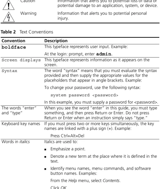
Conventions Table 1 and Table 2 list conventions that are used throughout this guide.
Table 1 Notice Icons
Icon Notice Type Description
Information note Information that describes important features or instructions.
Caution Information that alerts you to potential loss of data or potential damage to an application, system, or device. Warning Information that alerts you to potential personal
injury.
Table 2 Text Conventions Convention Description
boldface This typeface represents user input. Example:
At the login: prompt, enteradmin.
Screen displays This typeface represents information as it appears on the screen.
Syntax The word “syntax” means that you must evaluate the syntax provided and then supply the appropriate values for the placeholders that appear in angle brackets. Example: To change your password, use the following syntax:
system password <password>
In this example, you must supply a password for <password>. The words “enter”
and “type”
When you see the word “enter” in this guide, you must type something, and then press Return or Enter. Do not press Return or Enter when an instruction simply says “type.” Keyboard key names If you must press two or more keys simultaneously, the key
names are linked with a plus sign (+). Example: Press Ctrl+Alt+Del
Words in italics Italics are used to:
■ Emphasize a point.
■ Denote a new term at the place where it is defined in the
text.
■ Identify menu names, menu commands, and software
button names. Examples:
From the Help menu, select Contents. Click OK.
Related Documentation 9
Related
Documentation
In addition to this guide, the documentation set includes the following:
■ Release Notes (PDF format)
These notes provide information about the current software release, including new features, modifications, and known problems. These release notes are available in PDF format and are accessible from the 3Com web site.
There are other publications you may find useful, such as:
■ Documentation accompanying the Advanced Redundant Power
System.
■ Documentation accompanying the 3Com® Network Supervisor.
Product Registration
You can register your SuperStack 3 Server Load Balancer on the 3Com Web site to receive up-to-date information on your product:
http://support.3com.com/registration/frontpg.pl
Documentation Comments
Your suggestions are very important to us. They will help make our documentation more useful to you. Please e-mail comments about this document to 3Com at:
Please include the following information when commenting:
■ Document title
■ Document part number (on the title page)
■ Page number (if appropriate)
Example:
■ SuperStack 3 Server Load Balancer and Server Load Balancer Plus User
Guide
■ Part Number 990-XXXX-XX
1
I
NTRODUCING
THE
S
ERVER
L
OAD
B
ALANCER
This chapter contains introductory information about the SuperStack® 3 Server Load Balancer and the SuperStack 3 Server Load Balancer Plus. It covers summaries of the following topics:
■ About the Server Load Balancer
■ Server Load Balancer — Front View Detail
■ Server Load Balancer — Rear View Detail
■ Downloading 3Com Network Supervisor
Unless otherwise noted, the information in this chapter applies to both the Server Load Balancer and the Server Load Balancer Plus.
12 CHAPTER 1: INTRODUCINGTHE SERVER LOAD BALANCER
About the Server Load Balancer
The SuperStack® 3 Server Load Balancer and Server Load Balancer Plus
provide support for connecting multiple high-performance servers to a Gigabit backbone and providing server load balancing, cache redirection and security functionality.
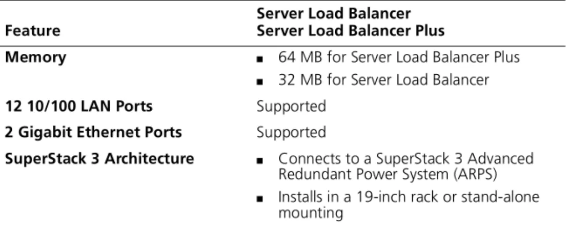
Summary of Hardware Features
Table 3 summarizes the hardware features that are supported in both models of the Server Load Balancer.
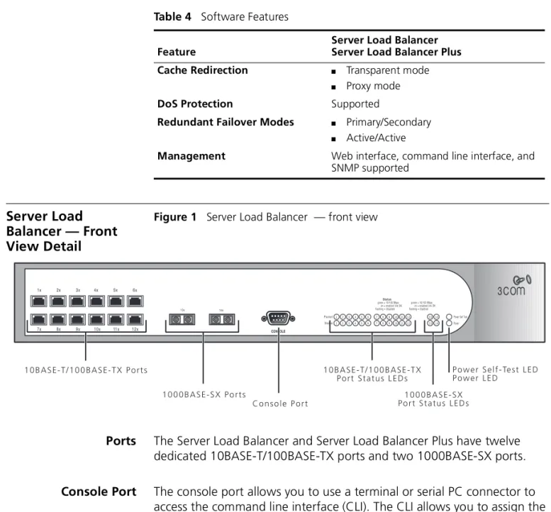
Summary of Software Features
Table 4 summarizes the software features that are supported in both models of the Server Load Balancer.
Table 3 Hardware Features
Feature
Server Load Balancer Server Load Balancer Plus
Memory ■ 64 MB for Server Load Balancer Plus ■ 32 MB for Server Load Balancer
12 10/100 LAN Ports Supported
2 Gigabit Ethernet Ports Supported
SuperStack 3 Architecture ■ Connects to a SuperStack 3 Advanced
Redundant Power System (ARPS)
■ Installs in a 19-inch rack or stand-alone
mounting
Table 4 Software Features
Feature
Server Load Balancer Server Load Balancer Plus Algorithms ■ Round Robin
■ Weighted Round Robin ■ Least Connections ■ Quickest Last Response ■ Quickest Average Response ■ Weighted Percentage
Port Trunking (Etherchannel) Supported
Up to 256 servers Supported
TCP/IP Sessions ■ 16,000 for the Server Load Balancer ■ 128,000 for the Server Load Balancer Plus
Persistence Modes ■ Source IP
■ Secure Socket Layer (SSL) Session ID ■ Cookie
Server Load Balancer — Front View Detail 13
Server Load Balancer — Front View Detail
Figure 1 Server Load Balancer — front view
Ports The Server Load Balancer and Server Load Balancer Plus have twelve
dedicated 10BASE-T/100BASE-TX ports and two 1000BASE-SX ports. Console Port The console port allows you to use a terminal or serial PC connector to
access the command line interface (CLI). The CLI allows you to assign the IP address to the Service Load Balancer and provides basic configuration capabilities. For console port pin-out information, see Appendix B.
Cache Redirection ■ Transparent mode ■ Proxy mode
DoS Protection Supported
Redundant Failover Modes ■ Primary/Secondary ■ Active/Active
Management Web interface, command line interface, and SNMP supported
Table 4 Software Features
Feature
Server Load Balancer Server Load Balancer Plus
1 23 4 5 6 7 89 101112 1 23 4 5 6 7 89 101112
14 13
14 13
1 0 0 0 B A S E - S X P o r t s
C o n s o l e P o r t
1 0 B A S E - T / 1 0 0 B A S E - T X P o r t S t a t u s L E D s
1 0 0 0 B A S E - S X P o r t S t a t u s L E D s
P o w e r S e l f - Te s t L E D P o w e r L E D 1 0 B A S E - T / 1 0 0 B A S E - T X P o r t s
14 CHAPTER 1: INTRODUCINGTHE SERVER LOAD BALANCER
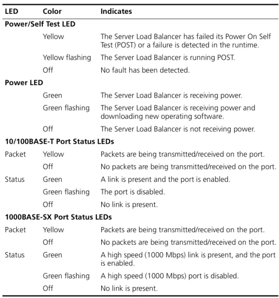
LEDs Table 5 lists LEDs visible on the front of the Server Load Balancer, and how
to read their status according to color.
Table 5 LED Behavior
LED Color Indicates Power/Self Test LED
Yellow The Server Load Balancer has failed its Power On Self Test (POST) or a failure is detected in the runtime. Yellow flashing The Server Load Balancer is running POST. Off No fault has been detected.
Power LED
Green The Server Load Balancer is receiving power. Green flashing The Server Load Balancer is receiving power and
downloading new operating software.
Off The Server Load Balancer is not receiving power.
10/100BASE-T Port Status LEDs
Packet Yellow Packets are being transmitted/received on the port. Off No packets are being transmitted/received on the port. Status Green A link is present and the port is enabled.
Green flashing The port is disabled. Off No link is present.
1000BASE-SX Port Status LEDs
Packet Yellow Packets are being transmitted/received on the port. Off No packets are being transmitted/received on the port. Status Green A high speed (1000 Mbps) link is present, and the port
is enabled.
Green flashing A high speed (1000 Mbps) port is disabled. Off No link is present.
Server Load Balancer — Rear View Detail 15
Server Load Balancer — Rear View Detail
Figure 2 Server Load Balancer — rear view
Unit Information Label
The labels on the rear of the unit show the following:
■ The 3Com product name of the Server Load Balancer
■ The 3Com 3C number of the Server Load Balancer
■ The unique MAC address (Ethernet address) of the Server Load
Balancer
■ The serial number of the Server Load Balancer
You may need this information for fault reporting purposes.
Power Socket The Server Load Balancer automatically adjusts its power setting to any
supply voltage in the range 90-240 VAC. Advanced Redundant
Power System Socket
To protect against internal power supply failure, you can use this socket to connect a Advanced Redundant Power System (ARPS) (part number 3C16075) to the Server Load Balancer. For more information on the Advanced Redundant Power System, see the documentation shipped with the power system.
For normal redundancy, the unit requires one Type 3 Power Module (part number 3C16075).
For full redundancy, the unit requires two Type 3 Power Modules combined using a Type 3 Y-Cable (part number 3C16077).
L a s e r w a r n i n g a n d S u p p l y w a r n i n g L a b e l
R e d u n d a n t P o w e r S y s t e m S o c k e t P o w e r S o c k e t
16 CHAPTER 1: INTRODUCINGTHE SERVER LOAD BALANCER
CAUTION:The Server Load Balancer can only use a SuperStack Advanced Redundant Power System output.
WARNING:If you are connecting the Server Load Balancer to a ARPS Type 3 Power Module, read the Safety Information section in the documentation shipped with the power system.
CAUTION:The Server Load Balancer has no ON/OFF switch; the only method of connecting or disconnecting main power is by connecting or disconnecting the power cord.
Downloading 3Com Network Supervisor
You can download 3Com Network Supervisor Version 3.0 from the following Web address:
http://www.3com.com/tns
Network Supervisor is a powerful, intuitive network management application for small to medium enterprise networks.
Network Supervisor automatically discovers up to 1500 network devices and shows devices and connections on a graphical display. Network managers can view network activity, monitor stress and set thresholds and alerts. This information helps to provide the most efficient, cost-effective use of network resources.
Version 3.0 adds significant extra functionality designed to detect network inefficiency and optimize network performance. Features include support for related and recurring events, user definable reports, auto-alerting using pager or SMS messages and simple updates from the 3Com Web site.
2
I
NSTALLING
THE
S
ERVER
L
OAD
B
ALANCER
This chapter contains the information you need to install and set up the Server Load Balancer. It covers the following topics:
■ Package Contents
■ Choosing a Suitable Site
■ Rack-mounting
■ Placing Units On Top of Each Other
■ The Power-up Sequence
■ Solving Problems Indicated by LEDs
WARNING: Safety Information. Before installing or removing any components from the Server Load Balancer or carrying out any
maintenance procedures, you must read the safety information provided in Appendix Aof this guide.
AVERTISSEMENT:Consignes de sécurité. Avant d'installer ou d'enlever tout composant du Server Load Balancer ou d'entamer une procédure de maintenance, lisez les informations relatives à la sécurité qui se trouvent dans l'Appendice A de ce guide.
WARNHINWEIS: Sicherheitsinformationen. Bevor Sie Komponenten aus dem Server Load Balancer entfernen oder dem Server Load Balancer hinzufuegen oder Instandhaltungsarbeiten verrichten, lesen Sie die Sicherheitsanweisungen, die in Appendix A (Anhang A) in diesem Handbuch aufgefuehrt sind.
18 CHAPTER 2: INSTALLINGTHE SERVER LOAD BALANCER
Package Contents Your shipping container should contain the following items:
■ Server Load Balancer (3C11620)
or Server Load Balancer Plus (3C11621)
■ User Guide (this guide)
■ Power Cord
■ 2 x mounting brackets
■ 6 x screws
■ 4 x rubber feet
Choosing a Suitable Site
The Server Load Balancer is suited for use where it can be mounted in a standard 19-inch equipment rack, or free-standing. A rack-mounting kit, containing two mounting brackets and six screws is supplied with the unit.
CAUTION: Ensure that the ventilation holes are not obstructed.
When deciding where to position the Server Load Balancer, ensure that:
■ Cabling is located away from sources of electrical noise such as radios,
transmitters and broadband amplifiers.
■ Cabling is located away from power lines and fluorescent lighting
fixtures
■ The Server Load Balancer is accessible and cables can be connected
easily.
■ Water or moisture cannot enter the case of the Server Load Balancer.
■ Air-flow is not restricted around the Server Load Balancer or through
the vents in the side of the Server Load Balancer. 3Com recommends that you provide a minimum of 25 mm (1 in.) clearance.
■ The air is as free from dust as possible.
■ No more than four Server Load Balancer units are placed on top of
one another, if the units are free-standing.
■ Temperature operating limits are not exceeded. It is recommended
that the unit is installed in a clean, air conditioned environment.
■ Ensure there is adequate clearance at the front of the unit to ensure
Rack-mounting 19
Rack-mounting The Server Load Balancer is 1.5U and fits in most standard 19-inch racks. However, if you are connecting the Server Load Balancer to a ARPS Type 3 power module, a runner, shelf or tray is recommended to support the additional weight. You will need to allow a 2U space within the rack for each Server Load Balancer.
WARNING: The rack-mount kits alone are not sufficient to support the weight of the Server Load Balancer when attached to an ARPS power module. It is recommended that you use a runner, shelf or tray to support the total weight. The rack mount kits must not be used to suspend the Server Load Balancer from under a table or desk, or attach it to a wall.
CAUTION:You must use a full depth shelf or support that will not obstruct the air flow through the side panels of the Server Load Balancer.
CAUTION:Disconnect all cables from the Server Load Balancer before continuing. Remove all self adhesive pads from the underside of the Server Load Balancer if they have been fitted.
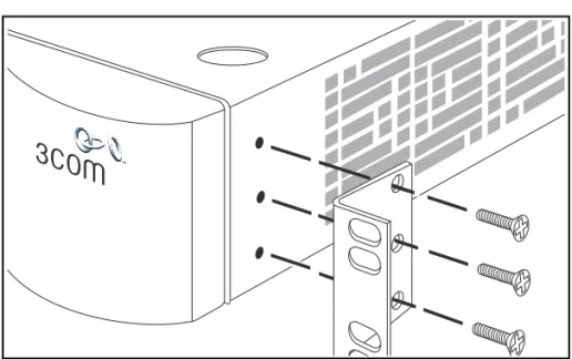
To rack-mount your Server Load Balancer:
1 Place the unit the right way up on a hard flat surface, with the front
facing towards you.
2 Locate a mounting bracket over the mounting holes on one side of the
unit, as shown in Figure 3.
20 CHAPTER 2: INSTALLINGTHE SERVER LOAD BALANCER
You must use the screws supplied with the mounting brackets. Damage caused to the unit by using incorrect screws invalidates your warranty.
3 Insert the three screws and tighten with a suitable screwdriver.
4 Repeat steps 2 and 3 for the other side of the unit.
5 Insert the unit into the 19-inch rack and secure with suitable screws (not
provided). Ensure that ventilation holes are not obstructed.
6 Connect network cabling.
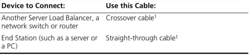
Choosing the Correct Cables
The 1000BASE-FX fiber optic LAN ports (Ports 13 and 14) on the Server Load Balancer use SC connectors. The 10BASE-T/100BASE-TX copper LAN ports (Ports 1 through 12) use RJ45 connectors.
Table 6 explains cables to use before connecting a device to the copper ports.
1 Cables are not supplied by 3Com.
Placing Units On Top of Each Other
If the units are free-standing, up to four units can be placed one on top of the other.
If you are placing units one on top of the other, you must use the self-adhesive rubber feet supplied. Apply the feet to the underside of each unit, sticking one in the marked area at each corner. Place the units on top of each other, ensuring that the feet of the upper unit line up with the recesses of the lower unit.
Table 6 Cabling for Copper Ports
Device to Connect: Use this Cable:
Another Server Load Balancer, a network switch or router
Crossover cable1
End Station (such as a server or a PC)
The Power-up Sequence 21
The Power-up Sequence
The following sections describe how to get your Server Load Balancer powered-up and ready for operation.
WARNING:If you are connecting the Server Load Balancer to a ARPS Type 3 Power Module, read the Safety Information section in the documentation shipped with the power system.
Powering-up To power-up the Server Load Balancer, complete the following steps:
1 Plug the power cord into the power socket at the rear of the unit.
2 Plug the other end of the power cord into your power outlet.
The unit powers-up and runs through its Power On Self Test (POST), which takes approximately 10 seconds.
During the POST, all ports on the Server Load Balancer are disabled and the LEDs light in a rapid sequence. See “LEDs” on page 14.
When the POST has completed, check the Power/Self Test LED to make sure that your Server Load Balancer is operating correctly. See “Solving Problems Indicated by LEDs” on page 22.
22 CHAPTER 2: INSTALLINGTHE SERVER LOAD BALANCER
Solving Problems Indicated by LEDs
Table 7 contains a list of problems and suggested solutions if the LEDs indicate a problem. For Technical Support information, see Appendix C.
Table 7 Problems Indicated by LEDs
Problem Suggested Solution The Power LED does
not light
Check that the power cable is firmly connected to the relevant unit and to the supply outlet. If the connection is secure and there is still no power, you may have a faulty power cord.
On powering-up, the Power/Self Test LED lights yellow
The relevant unit has failed its Power On Self Test (POST) because of an internal problem. Contact your supplier for advice.
A link is connected and yet the Status LED for the port does not light
Check that:
■ All connections are secure.
■ The devices at both ends of the link are powered-up. ■ The devices at both ends of the link have the same
auto-negotiation setting, i.e. both enabled, or both disabled.
■ The quality of cable is satisfactory. ■ The correct type of cable (crossover or
3
S
ETTING
U
P
FOR
M
ANAGEMENT
This chapter explains the management methods used for managing a Server Load Balancer, and details the steps required before you can configure a Server Load Balancer to suit the needs of your network. It covers the following topics:■ Methods of Managing the Server Load Balancer
24 CHAPTER 3: SETTING UPFOR MANAGEMENT
Methods of Managing the Server Load Balancer
You can manage a Server Load Balancer using one of the following methods:
■ Web interface management — Each Server Load Balancer has a set of
internal Web pages that allow you to manage the Server Load Balancer using a Web browser. Using the Web interface is the preferred method of management.
■ Command line interface management — The Server Load Balancer
offers limited command line interface (CLI) commands to configure basic parameters, such as the management IP Address.
■ SNMP management — You can manage a Server Load Balancer using
any Network Manager running the Simple Network Management Protocol (SNMP), such as 3Com Network Supervisor software. SNMP management is limited and does not allow for full configuration functionality.
Assigning an IP Address
To manage a Server Load Balancer over the network, the Server Load Balancer must be initially configured with the following:
■ An IP address and subnet mask
■ A default route
The CLI provides a series of online instructions that you need to complete the setup process.
To assign an IP address to the Server Load Balancer, complete the following steps:
1 Connect your management station to the console port on the front the
Server Load Balancer. See “Console Port Cable” on page 84.
2 On a Windows® PC, you may use the Hyperterminal program or other
terminal emulator. The correct settings are:
■ Bits per second: 9600
■ Data bits: 8
■ Parity: None
■ Stop bits: 1
Assigning an IP Address 25
3 Hit <Return>. At the login: prompt, enter admin.
The Server Load Balancer provides two levels of access, admin and
monitor. The password field contains blank default login passwords. The
two levels of access are:
■ admin — the user can access and change all manageable
parameters
■ monitor — the user can view all manageable parameters, but
cannot change any parameters
4 At the password: prompt, hit <Return>. The password field contains
a blank default login password. The Welcome to the SLB Setup CLI
appears.
CAUTION: The Server Load Balancer does not provide a way to recover a lost password. If you choose to assign a new password, it is suggested you keep note of it in a safe place. If you forget your password, you will be locked out of the unit. If you change the password during the CLI Server Load Balancer setup, this is the password you should use, and not the blank default login password. For Technical Support, see Appendix C.
Welcome to the SLB Setup
Follow the on-screen instructions to complete the setup process.
You may run setup later by typing “setup” at the SEC> prompt. Setup will take you through the following steps:
SEC>
1. Set unit ip address 2. Set default route 3. Set clock
4. Set login password
You may use <CR> to skip a step.
Enter unit ip in this format: nnn.nnn.nnn.nnn/pp where: nnn.nnn.nnn.nnn is IP address
26 CHAPTER 3: SETTING UPFOR MANAGEMENT
5 You are prompted to enter the following information:
a a unit IP address
b a default route
c the local time
d the local date
e the number of desired time zone (1-107 options)
f a new login password
g confirm new login password
6 Once you have completed the setup, exit the CLI.
You are now ready to access the Server Load Balancer Web interface. See “Accessing the Web Interface”on page 30.
4
W
ORKING
W
ITH
THE
W
EB
I
NTERFACE
This chapter describes how to access and use the web interface. It covers the following topics:
■ Choosing a Browser
■ Accessing the Web Interface
■ Using the Web Interface
■ Setting up SNMP Management
28 CHAPTER 4: WORKING WITHTHE WEB INTERFACE
Choosing a Browser To display the Web interface correctly, use one of the following Web browsers:
■ Netscape Navigator® version 4.5 or above.
■ Microsoft® Internet Explorer version 5.0 or above.
For the browser to operate the Web interface correctly, the Java Runtime Environment (JRE) V1.3.0_02 or higher must be installed on your
management workstation.
A version of the JRE plug-in for Windows® is provided on the Server Load Balancer. If you do not already have the plug-in installed on your
management station, you will be prompted to install it. See either “Installing the JRE for Microsoft Internet Explorer” or “Installing the JRE for Netscape Navigator”.
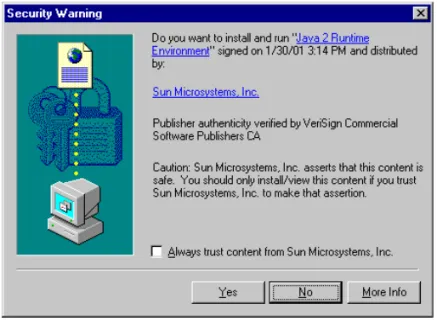
Installing the JRE for Microsoft Internet Explorer
If you are using Microsoft Internet Explorer for your browser and do not have the Java Runtime Environment installed on your management
station, the Security Warning window appears. Click Yes and follow the
on-line instructions.
Choosing a Browser 29
Installing the JRE for Netscape Navigator
If you are using Netscape Navigator for your browser and do not have the Java Runtime Environment installed on your management station, the
Web Interface pages appears.
Figure 5 Web Interface - Netscape
To install the plug-in, complete the following steps:
1 Click on Click here to get the plug-in.
2 The Plug-in Not Loaded window appears. Click Get the plug-in. The
Plug-in Install for Netscape page appears.
3 Click Download Plug-in. The Save As window appears.
4 Save the file to your Desktop.
5 From your desktop, double-click on jre1_3_0.exe.
30 CHAPTER 4: WORKING WITHTHE WEB INTERFACE
Accessing the Web Interface
To access the Web interface over the network, complete the following
steps:
1 Ensure that your network is correctly set up for management using the
Web interface and open your Web browser.
2 In the Location field of the browser, enter the URL of the Server Load
Balancer. This must be in the format:
http://nnn.nnn.nnn.nnn/
where nnn.nnn.nnn.nnn is the IP address you assigned in “Assigning an
IP Address” on page 24.
When the browser has located the Server Load Balancer, the Enter
Network Password window appears.
3 Enter admin in the User Name field.
The Server Load Balancer provides two levels of access, admin and
monitor. The password field contains a blank default login password. The
two levels of access are:
■ admin — the user can access and change all manageable
parameters
■ monitor — the user can view all manageable parameters, but
cannot change any parameters
4 The password field contains a blank default login password. Hit
<Return>.
CAUTION: The Server Load Balancer does not provide a way to recover a lost password. If you choose to assign a new password, it is suggested you keep note of it in a safe place. If you forget your password, you will be locked out of the unit. If you change the password during the CLI Server Load Balancer setup, this is the password you should use, and not the blank default login password. For Technical Support, see Appendix C.
The main Web interface is displayed. See “Using the Web Interface” on page 31.
Exiting the Web interface
You can exit the Web interface at any time; to do this, close your Web browser. For security reasons, you should always close your Web browser after a management session.
Using the Web Interface 31
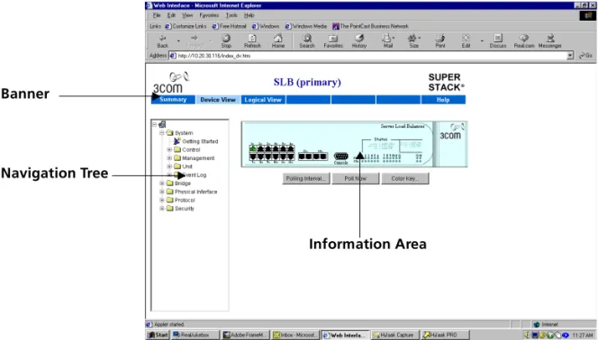
Using the Web Interface
The Web interface is made up of three areas:
■ The Banner
This is always displayed at the top of the browser window. It displays the name of the current Server Load Balancer, and contains several external links that allow you to access information outside of the Web interface.
■ The Navigation Tree
This is always displayed down the left side of the browser window. It contains management folders that display dialog boxes in the information area.
■ The Information Area
This is always displayed in the center of the browser window. It contains the various dialog boxes that allow you to manage the Server Load Balancer.
Figure 6 Parts of the main Web interface
Information Area Banner
32 CHAPTER 4: WORKING WITHTHE WEB INTERFACE
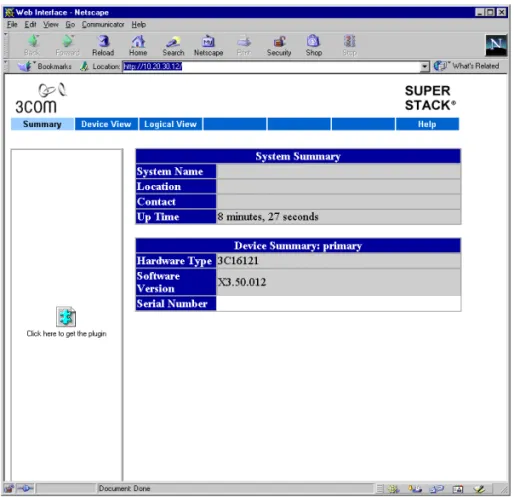
Summary View The Summary View displays the latest information for the Server Load
Balancer.
The Summary View only displays information for the Server Load Balancer. You cannot perform any operations from this view. You must use the Device View and the Logical View to perform operations.
Figure 7 Summary View
The summary information is displayed in a two tables:
■ System Summary
The first table is entitled System Summary and displays the System Name, Location, Contact and Up Time.
■ Device Summary
The second table is entitled Device Summary and displays the hardware type, software version, and serial number for the Server Load Balancer.
Using the Web Interface 33
Device View The Device View contains a mimic of the Server Load Balancer. The device
mimic is an interactive representation of the Server Load Balancer. It is periodically updated to reflect changes, particularly changes made to the status of its ports. This view is used to configure fundamental system and port operating parameters. To configure server load balancing, cache redirection and other features, use the Logical View.
While the Device View allows you to configure using the graphical user interface, there are some features that can only be configured from the Navigation Tree.
You can setup the Server Load Balancer by two methods; through the Navigation Tree or by clicking on the following device mimic "hotspots":
■ Port Hotspots
Each port on the mimic, including the console port, is a "hotspot". Click a port to open a pop-up menu that contains operations which you can launch for that particular port.
■ Unit Hotspot
The non-port area of the mimic is a "hotspot". Click anywhere on this area to open a pop-up menu that contains operations which you can launch for the Server Load Balancer as a whole.
34 CHAPTER 4: WORKING WITHTHE WEB INTERFACE
Figure 8 Device View
Control Buttons
Beneath the device mimic are three control buttons that you can use to control the mimic and its appearance and to provide help information:
■ Polling Interval — Click to set the rate at which the device mimic is
refreshed.
■ Poll Now — Click to refresh the mimic now.
■ Color Key — Click for an explanation of the symbols and colors on the
mimic's ports. Table 8 describes the colors and their actions.
Table 8 Color Key Codes
Color Action
Green Enabled, connected Black Enabled, disconnected Gray (with connection) Disabled, connected Gray (without connection) Disabled, disconnected
Navigation Tree
Port
Pop-up Menu Unit Pop-up Menu
Using the Web Interface 35
Logical View The Logical View presents a graphical view of the Server Load Balancer
configuration. This view is used to configure and monitor server load balancing, cache redirection and other high level device features. There are four blocks, each representing an area of configuration. Once configured, the entities will be listed in each block, and the approximate flow of data requests is indicated by the arrows.
You can configure the Server Load Balancer by two methods; through the Navigation Tree or by clicking on the top half of the block. Each colored portion of the block has a "hotspot". Click on a the block to open a pop-up menu that contains operations you can use to configure the Server Load Balancer.
While the Logical View allows you to configure using the graphical user interface, there are some features that can only be configured from the Navigation Tree.
Figure 9 Logical View
Navigation
Tree Block
Pop-Up Menu
36 CHAPTER 4: WORKING WITHTHE WEB INTERFACE
In addition to the blocks, there are three buttons that can be used to assign permissions, and server and cache assignments. Table 9 describes the buttons and their actions.
Table 9 Buttons and their actions Button Action
Permissions Displays a matrix of user groups versus virtual services displaying access rights of deny or allow.
Server Assignments Displays a matrix of virtual services versus physical servers. This display shows which servers are used for each virtual service and the operational status of the mappings.
Cache Assignments Displays a matrix of cache servers. This display shows which cache server are used for each virtual service and the operational status of the mappings.
Using the Web Interface 37
Help View The Help view contains important information on Web Browser and PC
platform combinations that are recommended when accessing the Web interface. The Help view also supplies minimal online user
documentation.
If your management workstation has access to the World Wide Web,
clicking these links displays information from the 3Com Web site in a second browser window.
38 CHAPTER 4: WORKING WITHTHE WEB INTERFACE
Setting up SNMP Management
You can manage a Server Load Balancer using any Network Manager running the Simple Network Management Protocol (SNMP), such as 3Com Network Supervisor software.
Specifying Community Strings
You can specify SNMP community strings for the users defined on the Server Load Balancer.
To specify the community strings, complete the following steps:
1 Click Device View on the Toolbar.
2 Select System > Management > Community Strings in the Navigation
Tree. The Community Strings window is displayed.
3 The Get Access Community String field is defaulted to public.
4 Select Set Access Enabled check box. This enables the access to the Server
Load Balancer. The Set Access Community String is defaulted to private.
5 Click OK.
Modifying a Trap Address
You can modify a trap address and its community string. The Server Load Balancer supports the following traps:
To modify a trap address, complete the following steps:
1 Click Device View on the Toolbar.
2 Select System > Management > Trap Address in the Navigation Tree. The
Modify Trap Address page appears. This page lists the ID, IP Address and the Community String.
3 Click on 2. The line becomes highlighted.
4 Click Modify. The Trap Address window appears.
5 The Trap Community String field is defaulted to public.
6 Enter 1.1.1.1 in the Trap IP Address field. The IP address you enter
should be the destination for this trap.
7 Click OK and close out of the Modify Trap Address page. You have now
modified the trap community string and the trap IP address.
■ Cold Start ■ Spanning Tree newRoot
■ Authentication Failure ■ Spanning Tree topologyChange
Upgrading Operating Software 39
Upgrading
Operating Software
You can upgrade the management software using the Software Upgrade
window.
CAUTION: It is suggested that when performing a software upgrade, you disable any security filters you have enabled. See“Modifying Security
Filters” on page 72.
To upgrade the software, complete the following steps:
1 Click Device View on the Toolbar.
2 Select System > Control > Software Upgrade in the Navigation Tree.
3 The Software Upgrade window is displayed.
4 Copy the software upgrade file into an appropriate directory on a TFTP
server.
5 Enter the name of the software field in the File name field. The filename
format is:
slbv350a.bin
CAUTION: You must use the slbv350a.bin format, otherwise the upgrade fails.
6 Enter the IP address of the TFTP server in the TFTP Server IP Address field.
7 Click OK.
During the upgrade, the Power/Self Test LED flashes green. The upgrade procedure takes about 5 minutes. When the upgrade is complete, the Server Load Balancer is reset.
CAUTION: During the upgrade, do not power-down or reset the Server Load Balancer.
5
C
ONFIGURING
N
ON
-
REDUNDANT
S
ERVER
L
OAD
B
ALANCING
In this chapter, a typical non-redundant server load balancing scenario is presented, with instructions for configuring the Server Load Balancer.
The information presented in this chapter is for example purposes only and actual addresses will vary.
The following is a list of steps for the scenario presented for configuring non-redundant server load balancing. These steps explained in detail in this chapter are:
■ Server Load Balancing Configuration Example
■ Configuring for Non-redundant Server Load Balancing
Before you complete the steps explained in this chapter, you must have completed the assigning IP address setup described in Chapter 3 Setting Up for Management.
42 CHAPTER 5: CONFIGURING NON-REDUNDANT SERVER LOAD BALANCING
Server Load Balancing Configuration Example
Figure 11 displays a network configuration of two primary servers, Server A and Server B. The servers have been set up to host a Web site to the public. Server A is assumed to be a powerful machine that has
approximately double the performance of Server B.
Figure 11 Server Load Balancing Configuration Example
Subnet 192.168.2.X
Client Internet
Server A 192.168.2.1 Port 80
Server B 192.168.2.2 Port 8080 Server Load Balancer
VIP: 10.20.30.117 IF1: 10.20.30.116 IF2: 192.168.2.254 Router Port 1
Port 5
Port 6 10.20.30.0
Configuring for Non-redundant Server Load Balancing 43
Configuring for Non-redundant Server Load Balancing
You must complete the steps in the Getting Started wizard to configure
the Server Load Balancer for non-redundant server load balancing. To setup up a non-redundant configuration, complete the following steps:
1 Click Device View on the Toolbar.
2 Select System > Getting Started in the Navigation Tree. The first Getting
44 CHAPTER 5: CONFIGURING NON-REDUNDANT SERVER LOAD BALANCING
3 Enter a descriptive name, such as Non-redundant SLB, in the Name
field.
4 Enter the name of the person to contact about the Server Load Balancer,
such as Chris, in the Contact field.
5 Enter the physical location of the Server Load Balancer, such as Lab, in
the Location field.
6 Click Next. The Getting Started - Configuration page appears.
7 Select Non-Redundant.
8 Click Next. The Getting Started - IP Settings page appears.
The IP Address, Subnet Mask and Default Router fields are completed. This is the information you assigned to the Server Load Balancer during the CLI setup.
If you change these settings, you may lose IP connectivity to the Web interface upon completion of this wizard. If this occurs, you will need to reconnect to the Server Load Balancer using the new IP address.
9 Click Next. The Getting Started - Network Address Translation page
appears.
If you are using private IP subnets for your server or cache subnets and want the servers or caches to be able to initiate connections to the
outside, check NAT Enabled for Server and Cache Subnets. If
NAT is enabled, packets initiated by the servers and the caches need to be given an IP address on the primary IP subnet. This address is the alias address.
10 Click Next. The Getting Started - Password page appears.
CAUTION: The Server Load Balancer does not provide a way to recover a lost password. If you choose to assign a new password, it is suggested you keep note of it in a safe place. If you forget your password, you will be locked out of the unit. If you change the password during the CLI Server Load Balancer setup, this is the password you should use, and not the blank default login password. For Technical Support information, see Appendix C.
11 Click Finish. The parameters you have entered are ready to be applied.
You are now ready to configure the load balancing services. See Chapter 8 Configuring for Load Balancing.
6
C
ONFIGURING
R
EDUNDANT
S
ERVER
L
OAD
B
ALANCING
In this chapter, a typical redundant server load balancing scenario is presented, with instructions for configuring the Server Load Balancer.
The information presented in this chapter is for example purposes only and actual addresses will vary.
The following is a list of steps for the scenario presented for configuring redundant server load balancing. These steps explained in detail in this chapter are:
■ Configuring for Active-Passive Redundancy
■ Configuring for Active-Active Redundancy
■ Active-Active Device Allocation
■ Setting Redundancy Settings
Before you complete the steps explained in this chapter, you must have completed the preliminary setup described in Chapter 3 Setting Up for Management.
46 CHAPTER 6: CONFIGURING REDUNDANT SERVER LOAD BALANCING
Redundant Server Load Balancing Configuration Example
Figure 12 shows how two Server Load Balancers and three servers form a redundant Web service. Server Load Balancer 1 is the Primary server load balancer which actively handles client requests sent to the VIP. Server Load Balancer 2 automatically recognizes the settings on Server Load Balancer 1 and is configured for the same service.
Figure 12 Redundant Server Load Balancing Configuration Example
Router
L2 Switch
L2 Switch
Server Load Balancer 1 Server Load Balancer 2
Server A
IP: 192.168.2.1 Default Gtwy: Port: 80
Server B
IP: 192.168.2.2 Default Gtwy: Port: 8080
Server C
IP: 192.168.2.3 Default Gtwy: Port: 80
Subnet 10.20.30.X
Port 1 Port 1
Port 12 Port 12
Port 5 Floating IP Address 192.168.2.200 Port 5
Redundant Link
IP: 10.20.30.116
Peer IP Address: 10.20.30.56 Subnet Mask: 255.255.255.0 Default Router: 10.20.30.254
IP Address: 10.20.30.56 Subnet Mask: 255.255.255.0 Default Router: 10.20.30.254
Configuring for Active-Passive Redundancy 47
Configuring for Active-Passive Redundancy
You must complete the Getting Started wizard to configure the Server
Load Balancer for active-passive redundancy.
To setup up a for active-passive redundancy configuration, complete the following steps:
1 Click Device View on the Toolbar.
2 Select System > Getting Started in the Navigation Tree. The first Getting
Started page is displayed. Click Next.
3 Enter a descriptive name, such as Active-Passive, in the Name field.
4 Enter the name of the person to contact about the Server Load Balancer,
such as Bob, in the Contact field.
5 Enter the physical location of the Server Load Balancer, such as Office,
in the Location field. Click Next.
48 CHAPTER 6: CONFIGURING REDUNDANT SERVER LOAD BALANCING
7 Select the serial number of Device B. In this case, this is the second Server
Load Balancer.
If the device you wish to use as Device B does not appear in the list, check that the cable linking Device B to Device A is connected properly.
8 Click Next. The Getting Started - IP Settings page appears.
If you change these settings, you may lose IP connectivity to the Web interface upon completion of this wizard. If this occurs, you will need to reconnect to the Server Load Balancer using the new IP address
The IP Address, Subnet Mask and Default Router fields are completed. These is the information you assigned to the Server Load Balancer during the CLI setup.
9 Enter 10.20.30.56 in the Device B IP Address field.
This is the IP address assigned to the second Server Load Balancer.
10 Click Next. The Getting Started - Network Address Translation page
appears.
If you are using private IP subnets for your server or cache subnets and want the servers or caches to be able to initiate connections to the
outside, check NAT Enabled for Server and Cache Subnets. If
NAT is enabled, packets initiated by the servers and the caches need to be given an IP address on the primary IP subnet. This address is the alias address.
11 Click Next. The Getting Started - Password page appears.
CAUTION: The Server Load Balancer does not provide a way to recover a lost password. If you choose to assign a new password, it is suggested you keep note of it in a safe place. If you forget your password, you will be locked out of the unit. If you change the password during the CLI Server Load Balancer setup, this is the password you should use, and not the blank default login password. For Technical Support information, see Appendix C.
12 Click Next. The Getting Started - Advanced page appears
13 Click Continue with Advanced Settings and click Next.
14 Select Active-Passive and click Next. The Getting Started - Summary page
appears.
Configuring for Active-Active Redundancy 49
Configuring for Active-Active Redundancy
You must complete the Getting Started wizard to configure the Server
Load Balancer for active-active redundancy.
To setup up an active-active redundancy configuration, complete the following steps:
1 Click Device View on the Toolbar.
2 Select System > Getting Started in the Navigation Tree. The first Getting
Started page is displayed. Click Next.
3 Enter a descriptive name, such as Active-Active, in the Name field.
4 Enter the name of the person to contact about the Server Load Balancer,
such as Dave, in the Contact field.
5 Enter the physical location of the Server Load Balancer, such as Lab, in
the Location field. Click Next.
6 Select Redundant and click Next. The Getting Started - Peer page
50 CHAPTER 6: CONFIGURING REDUNDANT SERVER LOAD BALANCING
7 Select the serial number of the peer device. In this case, the peer device is
the second Server Load Balancer.
8 Click Next. The Getting Started - IP Settings page appears.
If you change these settings, you may lose IP connectivity to the Web interface upon completion of this wizard. If this occurs, you will need to reconnect to the Server Load Balancer using the new IP address.
9 The IP Address, Subnet Mask and Default Router fields are completed.
These is the information you assigned to the Server Load Balancer during the CLI setup.
10 Enter 10.20.30.56 in the Device B IP Address field.
This is the IP address assigned to the second Server Load Balancer.
11 Click Next. The Getting Started - Network Address Translation page
appears.
If you are using private IP subnets for your server or cache subnets and want the servers or caches to be able to initiate connections to the
outside, check NAT Enabled for Server and Cache Subnets. If
NAT is enabled, packets initiated by the servers and the caches need to be given an IP address on the primary IP subnet. This address is the alias address.
12 Click Next. The Getting Started - Password page appears.
CAUTION: The Server Load Balancer does not provide a way to recover a lost password. If you choose to assign a new password, it is suggested you keep note of it in a safe place. If you forget your password, you will be locked out of the unit. If you change the password during the CLI Server Load Balancer setup, this is the password you should use, and not the blank default login password. For Technical Support information, see Appendix C.
13 Click Next. The Getting Started - Advanced page appears
14 Click Continue with Advanced Settings and click Next.
15 Select Active-Active and click Next. The Getting Started - Summary page
appears.
16 Click Finish. The parameters you have entered are ready to be applied.
You are now ready to configure the load balancing services. See Chapter 8 Configuring for Load Balancing.
Setting Redundancy Settings 51
Active-Active Device Allocation
Active-Active device allocation can only be performed when the Server Load Balancer has been configured to be redundant and active-active. The Active-Active device allocation page allows you to allocate which services are currently active on the two redundant Server Load Balancers. You can allocate FTP to one Server Load Balancer and HTTP to the other. The two Server Load Balancers each provide only the allocated services, until a failover occurs.
To setup up a active-active device allocation, complete the following steps:
1 Click Logical View on the Toolbar.
2 Select Server Load Balancing >Active-Active Device. The Active-Active
DeviceAllocation page is displayed.
3 Choose the virtual host(s) you wish to change the position of.
4 Click on the host and then click the appropriate arrow.
You are now ready to configure the load balancing services. See Chapter 8 Configuring for Load Balancing.
Setting Redundancy Settings
Whether you are configured for non-redundant or redundant server load balancing, if there are multiple Server Load Balancers, the Virtual Router Identifier (VRID) for each device must be unique or the service may not come up and one of the other Server Load Balancers declares itself the primary device.
To enter a unique number for the VRID, complete the following steps:
1 Click Logical View on the Toolbar.
2 Select Server Load Balancing > Redundancy Settingin the Navigation
Tree. The Redundancy Settings page is displayed.
3 Enter 25 in the Virtual router ID A field.
4 Enter 26 in the Virtual router ID B field.
7
C
ONFIGURING
C
ACHE
R
EDIRECTION
In this chapter, a typical application redirection scenario is presented, with directions for configuring the Server Load Balancer.
The information presented in this chapter is for example purposes only and actual addresses will vary.
The following list provides a checklist of the configuration steps for the scenario presented for configuring cache redirection on the Server Load Balancer. These steps are explained in detail in this chapter:
■ Defining a Cache Subnet
■ Non-redundant Configuration
■ Redundant Configuration
■ Adding a Cache
■ Assigning Caches to Services
54 CHAPTER 7: CONFIGURING CACHE REDIRECTION
Cache Redirection Configuration Example
Figure 13 illustrates a sample network configuration for cache redirection. This example displays how cache redirection works. A request is entered into the browser, for example,
http://www.3Com.com. The browser then sends the request to the Server Load Balancer.
The Server Load Balancer looks at the protocol and determines that it is the HTTP protocol and forwards the request to the cache server.
Upon receipt of the request, the cache server determines whether it has a local copy of the requested page. If not, the cache server sends its own request to www.3Com.com. When www.3Com.com responds to the cache server, the cache server forwards the response to the client, and if permitted, makes a local copy.
Figure 13 Cache Redirection Configuration Example
-Server Load
Internet Balancer
Web Browser
Server Server
Router
Cache Server
Defining a Cache Subnet 55
Defining a Cache Subnet
Before you can add a cache, you need to have defined at least one cache subnet.
The cache subnet cannot be in the same subnet as the server.
Non-redundant Configuration
The following steps describe how to create a cache subnet if you are configured for non-redundant server load balancing.
To create a cache subnet, complete the following steps:
1 Click Logical View on the Toolbar.
2 From the Navigation tree, select System > Setup > Cache Subnets.
3 Click Add. The first wizard page appears.
4 Click Next. The Cache Subnet - Configure Address page appears.
5 Enter 192.168.3.200 in the IP Address field.
6 Enter 255.255.255.0 in the Subnet Mask field.
7 Click Next. The Cache Subnet - Floating Address page appears.
8 Complete the entry in the Floating Address field. This is the floating
default gateway IP address. For example, 192.168.3.150.
Do not forget to change the default gateway on your caches to this IP address.
9 Click Next. The Cache Subnet page appears.
56 CHAPTER 7: CONFIGURING CACHE REDIRECTION
Redundant Configuration
The following steps describe how to create a cache subnet if you are configured for redundant server load balancing.
The cache subnet cannot be in the same subnet as the server.
To create a cache subnet, complete the following steps:
1 Click Logical View on the Toolbar.
2 From the Navigation tree, select System > Setup > Cache Subnets.
3 Click Add. The first wizard page appears.
4 Click Next. The Cache Subnet - Configure Address page appears.
5 Enter 192.168.3.200 in the Device A IP Address field.
6 Enter 192.168.3.100 in the Device B IP Address field.
7 Enter 255.255.255.0 in the Subnet Mask field.
8 Click Next. The Cache Subnet - Device A Floating Address page appears.
9 Complete the entry in the Device A Floating Address field. This is the
floating default gateway IP address. For example, 192.168.3.150.
Do not forget to change the default gateway on your caches to this IP address.
10 Click Next.
Adding a Cache 57
Adding a Cache This is where the cache service is defined, along with several attributes of the service.
1 Click Logical View on the Toolbar.
2 Point to the Cache window border and left-click the mouse button.
3 In the pop-up list, click Add. The Configure Cache page appears.
If you have not defined a cache subnet, you will be prompted with a Warning message asking if you wish to define the cache subnet now. See “Defining a Cache Subnet” on page 58.
4 Complete the entry in the IP Address field. For example, 192.168.3.1.
5 Enter Cache1 in the Name field.
6 Select the cache type and click Add. There are two available cache types:
■ Transparent
■ Proxy
7 Click Done.
Assigning Caches to Services
The Assign Caches to Services page is where the caches are assigned to cache redirection.
The Cache Assignments button is highlighted only if an HTTP service has been created.
1 Click Cache Assignments. The Assign Caches to Services page appears.
2 Click on the cell to assign a cache service.
3 Click on the cell next to Cache1. The Assign cache to service pop-up
menu appears.
4 Click Assign cache to service. The cell for Server A is assigned.